Duet3D Logo Duet3D
    • Tags
    • Documentation
    • Order
    • Register
    • Login

    500 Watt chinese spindle setup

    Scheduled Pinned Locked Moved Solved
    CNC
    6
    21
    1.7k
    Loading More Posts
    • Oldest to Newest
    • Newest to Oldest
    • Most Votes
    Reply
    • Reply as topic
    Log in to reply
    This topic has been deleted. Only users with topic management privileges can see it.
    • T3P3Tonyundefined
      T3P3Tony administrators @Jack_kelley
      last edited by

      @jack_kelley moved the the CNC forum.

      It looks like the PWM to analog module has two options:

      The peak-to-peak value is 4.5V to 10V, and the jumper cap is inserted at 5V. This type of level signal is mainly for the conventional industrial control card, 5V CPU interface;
      The peak-to-peak value is 12 to 24V, and the jumper cap is inserted at 24V. This type of level signal is mainly for the conventional PLC interface.

      The heater outputs on the Duet 2 should have VIN voltage on the VIN pin and the negative pin is switched ground (using PWM)

      www.duet3d.com

      Jack_kelleyundefined 1 Reply Last reply Reply Quote 0
      • Jack_kelleyundefined
        Jack_kelley @T3P3Tony
        last edited by

        @t3p3tony Thanks for your help, I wasn't sure if I should have put it in there.

        I am also using this cnc to expand my skills so at the moment I am not very competent with electronics. Do i need to plug into the duet in another place? I tried the jumper in both settings and they both produced the same result of a constant 5V

        alankilianundefined T3P3Tonyundefined 2 Replies Last reply Reply Quote 0
        • alankilianundefined
          alankilian @Jack_kelley
          last edited by alankilian

          @jack_kelley You should use an output pin that is NOT a heater pin since the heater pin switches the ground instead of the signal pin.

          They any other I/O pin that can be used as a PWM output on your board.

          SeemeCNC Rostock Max V3 converted to V3.2 with a Duet2 Ethernet Firmware 3.2 and SE300

          1 Reply Last reply Reply Quote 0
          • T3P3Tonyundefined
            T3P3Tony administrators @Jack_kelley
            last edited by

            @jack_kelley said in 500 Watt chinese spindle setup:

            I tried the jumper in both settings and they both produced the same result of a constant 5V

            I thought you meant the Duet produced constant 5V. Now I see you meant the spindle control.

            There are two options for a PWM output from the Duet 2. Either 3.3V PWM on the expansion header (here is an example using that):

            M950 R0 C"!exp.heater3" L12000 ; Create spindle index 0, with PWM pin on heater 3 and 12000 RPM achieved at full PWM
            M563 P1 S"Spindle 1" R0 ; Create tool 1 with spindle 0 and call it "Spindle 1"
            

            or the negative terminal of the heater or fan headers being PWMed.

            www.duet3d.com

            Jack_kelleyundefined 2 Replies Last reply Reply Quote 0
            • Jack_kelleyundefined
              Jack_kelley @T3P3Tony
              last edited by

              @t3p3tony Thanks for your help, Ill give that a shot tonight.

              1 Reply Last reply Reply Quote 0
              • Jack_kelleyundefined
                Jack_kelley @T3P3Tony
                last edited by

                @t3p3tony The converter cannot take a 3.3V signal, is there an option for a 5V pwm on these boards?
                f620fe08-6cac-4c7d-9f74-32cf6180d1cc-image.png

                1 Reply Last reply Reply Quote 0
                • cjmundefined
                  cjm
                  last edited by

                  To get the necessary 5V signal for this converter board you’ll need to add a pull up resistor.

                  @alankilian described a way of doing this here:

                  https://forum.duet3d.com/post/242329

                  The OP on this topic found @alankilian’s method worked with a 4.7K resistor value.

                  Jack_kelleyundefined 1 Reply Last reply Reply Quote 0
                  • Jack_kelleyundefined
                    Jack_kelley @cjm
                    last edited by

                    @cjm I have read through that thread and still dont quite understand where to put the resistor. Is there a schematic or a picture of where it should be anywhere?

                    cjmundefined 1 Reply Last reply Reply Quote 0
                    • cjmundefined
                      cjm @Jack_kelley
                      last edited by cjm

                      @jack_kelley
                      This connection for the pull up resistor should work:

                      8f637b4b-6eff-4a97-82eb-735d7592739f-image.png

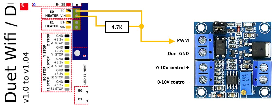
                      As this connection inverts the polarity of the PWM signal I think you will probably need to add an exclamation mark in front of the "e0heat" pin reference in your M950 config command, along the lines of:

                      ; CNC Mode (NB for Firmware 3.3+)
                      M453         			 ; CNC Mode 
                       
                      ; Configure Tool 0 as the CNC Spindle
                      M950 R0 C"!e0heat" Q2000 L0:12000	 ; Create spindle index 0 with
                                                               ; inverted PWM output on E0 heater pin
                                                               ; and spindle speed of 12000 rpm at maximum PWM
                      
                      M563 P0 R0 S"Spindle"            ; Create Tool 0 with Spindle 0 and call it Spindle 
                      G10  P0 X0 Y0 Z0                 ; Set Tool 0 axis offsets
                      M568 P0 F0			 ; Set Tool 0 to default RPM of 0
                      T0				 ; Select Tool 0
                      
                      Jack_kelleyundefined dc42undefined 2 Replies Last reply Reply Quote 0
                      • Jack_kelleyundefined
                        Jack_kelley @cjm
                        last edited by

                        @cjm Still only getting around 5V no matter is I run an M5 or M3 at full speed. Tried jumper cap at both locations. The only other thing i forgot to test was taking out the ! that you didnt seem sure needed to be there.

                        Color code
                        Orange- E0-
                        Yellow at breadboard-Vin E0
                        Red to PWM on converter
                        Yellow 24V
                        Black Ground
                        Maybe the pwm to analog converter is fried? 2782a88d-00d2-41c3-a95b-be21e3d86d81-image.png

                        cjmundefined 1 Reply Last reply Reply Quote 0
                        • cjmundefined
                          cjm @Jack_kelley
                          last edited by cjm

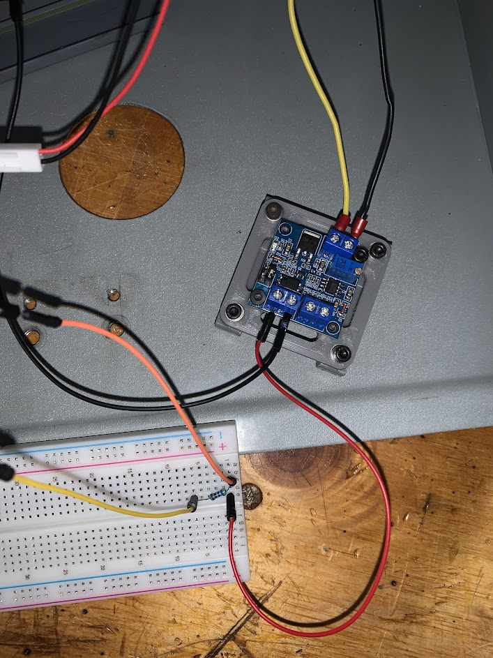
                          @jack_kelley OK, then I’d suggest using a multimeter to check:

                          a) that you have the correct DC input voltage on your Duet VIN (12V or 24V?)

                          b) that the output from the Duet E0 heater pin is behaving as expected by disconnecting the PWM converter board but leaving the 4.7K resistor in circuit and then measuring the DC voltage on the E0 heater pin for each of the following commands:

                          Command               Should give
                          M3 0                  Duet VIN  
                          M3 6000               Duet VIN/2
                          M3 12000              0V


                          If both a) and b) check out, then your PWM board is probably dead.

                          1 Reply Last reply Reply Quote 0
                          • dc42undefined
                            dc42 administrators @cjm
                            last edited by dc42

                            @Jack_kelley you need to use this connection between the PWM input connector of the converter board and the Duet:

                            • PWM pin to VIN on the Duet E0 output
                            • GND pin on the PWM input connector to E0- on the Duet (and nowhere else)

                            Select the jumper position on the converter board so that the PWM input accepts 12 to 24V.

                            This connection is OK for converter boards with optically isolated inputs, such as the one you have. The GND pin on the PWM input connector is a misleading name, it should be called PWM- or something like that.

                            Duet WiFi hardware designer and firmware engineer
                            Please do not ask me for Duet support via PM or email, use the forum
                            http://www.escher3d.com, https://miscsolutions.wordpress.com

                            cjmundefined 1 Reply Last reply Reply Quote 0
                            • cjmundefined
                              cjm @dc42
                              last edited by

                              @dc42 From the image of the PCB, I believe this is another of those converter boards with an opto-isolator whose purpose is negated by being connected to ground on the board.
                              Hence the @alankilian connection with a pull up resistor is needed.

                              dc42undefined 1 Reply Last reply Reply Quote 0
                              • dc42undefined
                                dc42 administrators @cjm
                                last edited by dc42

                                @cjm I see what you mean. Best option may be to use a scalpel or similar on the PCB to isolate the GND pins on the PWM connector and opto isolator; or buy a PWM converter without such an obvious design flaw. Having a shared ground between the Duet and a 500W spindle controller would be a bad idea.

                                Duet WiFi hardware designer and firmware engineer
                                Please do not ask me for Duet support via PM or email, use the forum
                                http://www.escher3d.com, https://miscsolutions.wordpress.com

                                cjmundefined 1 Reply Last reply Reply Quote 0
                                • cjmundefined
                                  cjm @dc42
                                  last edited by cjm

                                  @dc42 The board looks to be double sided so one would have to desolder the terminal and cut both sides of the PCB - might be doable but not straightforward.

                                  I agree that having a common Duet-VFD ground is not optimal, but this board has used by others successfully using the pull-up resistor approach.

                                  A properly opto-isolated VFD interface board that provides a 0-10v analogue control signal and RUN, FWD/REV control signals (and ideally rpm feedback) would be a useful add-on for the growing Duet eco-system and make life simpler for many CNC users.

                                  dc42undefined 1 Reply Last reply Reply Quote 0
                                  • dc42undefined
                                    dc42 administrators @cjm
                                    last edited by dc42

                                    @cjm said in 500 Watt chinese spindle setup:

                                    The board looks to be double sided so one would have to desolder the terminal and cut both sides of the PCB - might be doable but not straightforward.

                                    Is there really a ground plane on both sides? Usually a ground plane is on one side only.

                                    I think this style of converter board is OK. I have one, so I can check.

                                    1cccd261-17bf-4d31-8827-312dbe7e5f7e-image.png

                                    EDIT: confirmed, the input is isolated from the output on this type.

                                    Duet WiFi hardware designer and firmware engineer
                                    Please do not ask me for Duet support via PM or email, use the forum
                                    http://www.escher3d.com, https://miscsolutions.wordpress.com

                                    Jack_kelleyundefined CNCModellerundefined 2 Replies Last reply Reply Quote 0
                                    • Jack_kelleyundefined
                                      Jack_kelley @dc42
                                      last edited by

                                      @dc42
                                      I have one of those coming today, it has a 3.3V PWM input so it should be much more simple to setup. Ill update when I give it a shot. Thanks for the help everyone.

                                      https://www.amazon.com/dp/B079B5MRQC?psc=1&ref=ppx_yo2_dt_b_product_details

                                      dc42undefined 1 Reply Last reply Reply Quote 0
                                      • dc42undefined
                                        dc42 administrators @Jack_kelley
                                        last edited by

                                        @jack_kelley said in 500 Watt chinese spindle setup:

                                        @dc42
                                        I have one of those coming today, it has a 3.3V PWM input so it should be much more simple to setup. Ill update when I give it a shot. Thanks for the help everyone.

                                        https://www.amazon.com/dp/B079B5MRQC?psc=1&ref=ppx_yo2_dt_b_product_details

                                        The one I have has a jumper for either 5V or 24V input. I don't know whether on the 5V setting it will work with 3.3V input. Using the 24V position, you can connect it to a heater or fan output as I suggested earlier (which as @cjm pointed out, won't work with the other sort).

                                        Duet WiFi hardware designer and firmware engineer
                                        Please do not ask me for Duet support via PM or email, use the forum
                                        http://www.escher3d.com, https://miscsolutions.wordpress.com

                                        Jack_kelleyundefined 1 Reply Last reply Reply Quote 0
                                        • Jack_kelleyundefined
                                          Jack_kelley @dc42
                                          last edited by

                                          @dc42 After wiring one backwards and blowing a capacitor and ordering another one I finally got spindle speed control. Thanks everyone.

                                          If its help to anyone in the future here is my config for the spindle.

                                          ; Attemping to setup spindle

                                          ; CNC Mode (NB for Firmware 3.3+)
                                          M453 ; CNC Mode

                                          ; Configure Tool 0 as the CNC Spindle
                                          M950 R0 C"e0heat" Q2000 L12000 ; Create spindle index 0 with
                                          ; inverted PWM output on E0 heater pin
                                          ; and spindle speed of 12000 rpm at maximum PWM

                                          M563 P0 R0 S"Spindle" ; Create Tool 0 with Spindle 0 and call it Spindle
                                          G10 P0 X0 Y0 Z0 ; Set Tool 0 axis offsets
                                          M568 P0 F0 ; Set Tool 0 to default RPM of 0
                                          T0 ; Select Tool 0

                                          1 Reply Last reply Reply Quote 1
                                          • CNCModellerundefined
                                            CNCModeller @dc42
                                            last edited by CNCModeller

                                            @dc42 would that board be ok to use with the spindle drive on my denford novamil and novaturn?

                                            https://www.amazon.co.uk/dp/B0789738RC/ref=cm_sw_r_apan_glt_fabc_GEYTFG5YZRGZ0AMJC73Y?_encoding=UTF8&psc=1

                                            As I understand it the 0-10v floats on my spindle drive at about 110v above controller vref on both machines.

                                            For my previous attempts at controller conversion I ended up turning a pot with a servo. I gave up on that front and reverted to the OEM controller but have been looking for a better onboard controller solution ever since.

                                            If the 1HLC driver beta goes well I'm hoping to convert both my denfords over to Duet with linear scales, so I've started looking into this sort of thing again.

                                            Any thoughts would be much appreciated.

                                            Cheers
                                            Barry M

                                            ![Novamill](1d86e301-3a8f-4cc8-9fe0-1a762a57281a-image.png undefined)
                                            ![Novaturn](25278a52-f027-43db-aa08-a3817ce9995d-image.png undefined)

                                            Polar Duet3 Mini + 1HCL
                                            https://youtube.com/playlist?list=PLWjZVEdMv1BY82izahK45qKh-hp3NFkix
                                            Wanhao D4S: Duet2
                                            https://forum.duet3d.com/post/296755
                                            K40 Laser, Duet2
                                            https://forum.duet3d.com/post/312082
                                            Wanhao D5S
                                            https://www.youtube.com/CNCModellerUK

                                            1 Reply Last reply Reply Quote 0
                                            • First post
                                              Last post
                                            Unless otherwise noted, all forum content is licensed under CC-BY-SA