Duet3D Logo Duet3D
    • Tags
    • Documentation
    • Order
    • Register
    • Login

    Help me I think my endstops stopped

    Scheduled Pinned Locked Moved
    Duet Hardware and wiring
    4
    24
    703
    Loading More Posts
    • Oldest to Newest
    • Newest to Oldest
    • Most Votes
    Reply
    • Reply as topic
    Log in to reply
    This topic has been deleted. Only users with topic management privileges can see it.
    • adalton5683undefined
      adalton5683
      last edited by

      So, I have converted my Ender V2 to Duet and added a Hemera and a budget BLtouch. Everything worked fine except when I went to create my mesh(assuming I know the right way) I click Mesh Bed Compensation it goes off the front of the bed. so I catch the off switch prior to crash. And so I made some adjustment to my offset and tried again and this time when I hit homeall it crashed into the X axis endstop for about 2 seconds until I could stop it.

      Now neither my X or Y endstops work; M119 shows not stopped for both positions. if I change it over to S0 the show no-endstop. so its not recognizing them.

      Ive tried:

      • reverting to last config.g/homex/y/z/all
        *completely re config.json-ing like deleted all my settings and reconfigured and got back to no adjustments.
        *reflashing the firmware

      Nothing is working to get this thing back to those endstops being working and it really seems like something has stop electrically working in there. This is redick. im a EE and I literally have done nothing incredible tortuous enough to fry a switch contact.

      So if anyone knowing the power routing or how that bus works that could hlep me out I would be eternally grateful to you. I am so sad that I spent a ton of money and havent even got a single print.

      Could the endstops circuitry just have went bad from a single small and not long X endstop crash? I literally have not touched it and now both y and X are toast it seems.

      Like could it be dust or metal shvings that are particle size that floated in or something? im freakin out. like this is the first issue that ive had with this board and I literall just got it and got it to the point of alllllmost being able to print.

      jay_s_ukundefined adalton5683undefined 2 Replies Last reply Reply Quote 0
      • jay_s_ukundefined
        jay_s_uk @adalton5683
        last edited by

        @adalton5683 post your current config. Setting them to S0 turns them off...

        Owns various duet boards and is the main wiki maintainer for the Teamgloomy LPC/STM32 port of RRF. Assume I'm running whatever the latest beta/stable build is

        adalton5683undefined 1 Reply Last reply Reply Quote 0
        • adalton5683undefined
          adalton5683 @adalton5683
          last edited by adalton5683

          @adalton5683 tried to post this thing like 100 times

          Heres My applicable gonfig.g area

          ; Configuration file for Duet 3 Mini 5+ (firmware version 3.3)
          ; executed by the firmware on start-up
          ;
          ; generated by RepRapFirmware Configuration Tool v3.3.10 on Sun Jan 23 2022 18:13:35 GMT-0600 (Central Standard Time)
          
          ; General preferences
          G90                                                   ; send absolute coordinates...
          M83                                                   ; ...but relative extruder moves
          M550 P"bEnder vE3D"                                   ; set printer name
          
          ; Network
          M552 S1                                               ; enable network
          M586 P0 S1                                            ; enable HTTP
          M586 P1 S0                                            ; disable FTP
          M586 P2 S0                                            ; disable Telnet
          
          ; Drives
          M569 P0.0 S0                                          ; physical drive 0.0 goes backwards
          M569 P0.1 S0                                          ; physical drive 0.1 goes backwards
          M569 P0.2 S1                                          ; physical drive 0.2 goes forwards
          M569 P0.3 S0                                          ; physical drive 0.3 goes backwards
          M584 X0.0 Y0.1 Z0.2 E0.3                              ; set drive mapping
          M350 X16 Y16 Z16 E16 I1                               ; configure microstepping with interpolation
          M92 X60.00 Y60.00 Z409.00 E409.00                     ; set steps per mm
          M566 X900.00 Y900.00 Z60.00 E300.00                   ; set maximum instantaneous speed changes (mm/min)
          M203 X9000.00 Y9000.00 Z180.00 E6000.00               ; set maximum speeds (mm/min)
          M201 X500.00 Y500.00 Z100.00 E2500.00                 ; set accelerations (mm/s^2)
          M906 X600 Y600 Z750 E1200 I30                         ; set motor currents (mA) and motor idle factor in per cent
          M84 S30                                               ; Set idle timeout
          
          ; Axis Limits
          M208 X0 Y0 Z0 S1                                      ; set axis minima
          M208 X230 Y230 Z250 S0                                ; set axis maxima
          
          ; Endstops
          M574 X1 S1 P"io5.in"                                  ; configure switch-type (e.g. microswitch) endstop for low end on X via pin io5.in
          M574 Y1 S1 P"io6.in"                                  ; configure switch-type (e.g. microswitch) endstop for low end on Y via pin io6.in
          M574 Z1 S2                                            ; configure Z-probe endstop for low end on Z
          
          ; Z-Probe
          M950 S0 C"io3.out"                                    ; create servo pin 0 for BLTouch
          M558 P9 C"!io3.in" H5 F120 T6000                       ; set Z probe type to bltouch and the dive height + speeds
          G31 P500 X-35 Y7 Z2.5                                 ; set Z probe trigger value, offset and trigger height
          M557 X20:200 Y20:200 S20                              ; define mesh grid
          
          ; Heaters
          M308 S0 P"temp0" Y"thermistor" T9880 B4185            ; configure sensor 0 as thermistor on pin temp0
          M950 H0 C"out0" T0                                    ; create bed heater output on out0 and map it to sensor 0
          M307 H0 B0 S0.80                                      ; disable bang-bang mode for the bed heater and set PWM limit
          M140 H0                                               ; map heated bed to heater 0
          M143 H0 S120                                          ; set temperature limit for heater 0 to 120C
          M308 S1 P"temp1" Y"thermistor" T100000 B4725 C7.06e-8 ; configure sensor 1 as thermistor on pin temp1
          M950 H1 C"out1" T1                                    ; create nozzle heater output on out1 and map it to sensor 1
          M307 H1 B0 S1.00                                      ; disable bang-bang mode for heater  and set PWM limit
          M143 H1 S300                                          ; set temperature limit for heater 1 to 300C


          ; Fans
          M950 F0 C"out3" Q30                                   ; create fan 0 on pin out3 and set its frequency
          M950 F1 C"out4" Q30                                   ; create fan 1 on pin out4 and set its frequency
          M950 F2 C"out5" Q30                                   ; create fan 2 on pin out5 and set its frequency
          
          M106 P0 C"PartCool" S0 H-1                            ; set fan 0 name and value. Thermostatic control is turned off
          M106 P1 C"HotEnd"   S1 H1 T60                         ; set fan 1 name and value. Thermostatic control is turned on
          M106 P2 C"CaseFan"  S  H-1                            ; set fan 2 name and value. Thermostatic control is turned off
          
          
          ; Tools
          M563 P0 S"HotEnd" D0 H1 F0                            ; define tool 0
          G10 P0 X0 Y0 Z0                                       ; set tool 0 axis offsets
          G10 P0 R0 S0                                          ; set initial tool 0 active and standby temperatures to 0C


          ; Custom settings are not defined
          M574 Z2 S1 P"io2.in"                                  ; configure active-high endstop for high end on Z
          ;M204 P600 T2000					                  ; Set accelerations (mm/s^2) for print and travel moves
          ;M912 P0 S-13						                  ; CPU temperature calibration
          ;M572 D0 S0.35						                  ; Pressure Advance
          ;M207 S6.5 R0.0 F4800 T4800 Z0.0 	                  ; Retraction
          ;M280 P0 S160					  	                  ; Clear any alarms
          M402								                  ; retract pin just in case


          ; Miscellaneous
          M501                                                  ; load saved parameters from non-volatile memory
          M911 S10 R11 P"M913 X0 Y0 G91 M83 G1 Z3 E-5 F1000"    ; set voltage thresholds and actions to run on power loss
          M552 S1
          
          
          1 Reply Last reply Reply Quote 0
          • adalton5683undefined
            adalton5683 @jay_s_uk
            last edited by adalton5683

            @jay_s_uk

            yeah I know it turns them off but I tried it. and yeah it only turned the bit to 0 so I swapped it back. Main thing is I think the bus they run on is no longer working. but I dont know how it could have shorted.

            Is there any kind of selector that I may have accidentally set in Gcode that turns them off? or removes the power from them?

            updated the last post with my full config

            jay_s_ukundefined 1 Reply Last reply Reply Quote 0
            • jay_s_ukundefined
              jay_s_uk @adalton5683
              last edited by

              @adalton5683 that looks fine, nothing I can see as being wrong.
              So are you saying that testing with M119 that they don't change from not stopped to stopped when triggered?
              You may want to install the endstops plugin to make it easier to test them https://github.com/Duet3D/DSF-Plugins/releases

              Owns various duet boards and is the main wiki maintainer for the Teamgloomy LPC/STM32 port of RRF. Assume I'm running whatever the latest beta/stable build is

              adalton5683undefined 1 Reply Last reply Reply Quote 0
              • adalton5683undefined
                adalton5683 @jay_s_uk
                last edited by

                @jay_s_uk
                yeah they show not stopped set to S0 and they show no-endstop when set to S1

                adalton5683undefined 1 Reply Last reply Reply Quote 0
                • adalton5683undefined
                  adalton5683 @adalton5683
                  last edited by

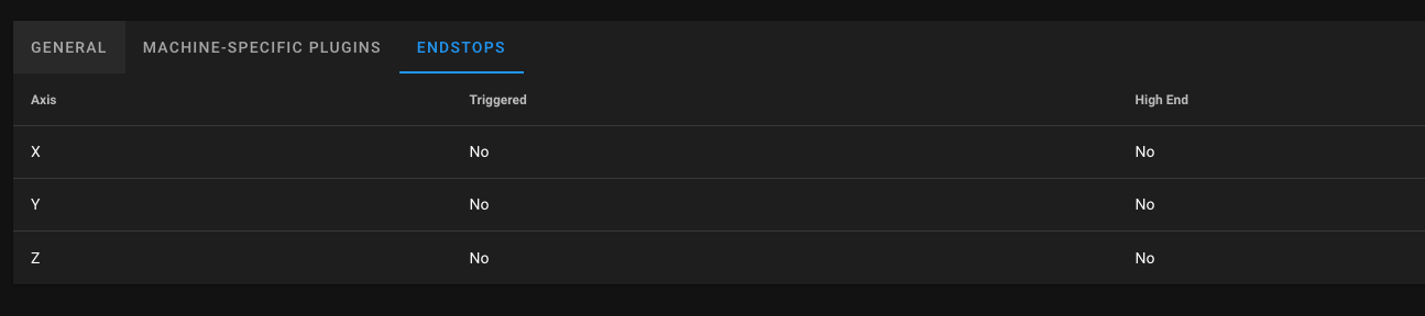
                  @adalton5683 Installed the plugin

                  when I hit the X or Y endstop the plugin shows no change. Both columns say no for all axes.

                  adalton5683undefined 1 Reply Last reply Reply Quote 0
                  • adalton5683undefined
                    adalton5683 @adalton5683
                    last edited by

                    @adalton5683![ ]Screen Shot 2022-01-25 at 12.32.17 AM.png )

                    adalton5683undefined 1 Reply Last reply Reply Quote 0
                    • adalton5683undefined
                      adalton5683 @adalton5683
                      last edited by

                      @adalton5683 @adalton5683 and it stays like that when either are activated.

                      jay_s_ukundefined 1 Reply Last reply Reply Quote 0
                      • jay_s_ukundefined
                        jay_s_uk @adalton5683
                        last edited by

                        @adalton5683 I would go through and check your wiring. If you have a multimeter, check that the endstop resistance changes when triggered. There's very little you can do to break the endstop inputs of the board

                        Owns various duet boards and is the main wiki maintainer for the Teamgloomy LPC/STM32 port of RRF. Assume I'm running whatever the latest beta/stable build is

                        alankilianundefined 1 Reply Last reply Reply Quote 0
                        • alankilianundefined
                          alankilian @jay_s_uk
                          last edited by

                          Does the board you are using have LEDs on the endstop inputs like the Duet2?

                          If so, make sure they switch from lit to unlit when you click the endswitches.

                          SeemeCNC Rostock Max V3 converted to V3.2 with a Duet2 Ethernet Firmware 3.2 and SE300

                          jay_s_ukundefined 1 Reply Last reply Reply Quote 0
                          • jay_s_ukundefined
                            jay_s_uk @alankilian
                            last edited by

                            @alankilian said in Help me I think my endstops stopped:

                            If so, make sure they switch from lit to unlit when you click the endswitches.

                            they won't always go lit to unlit if normally open (will go unlit to lit when pressed)

                            Owns various duet boards and is the main wiki maintainer for the Teamgloomy LPC/STM32 port of RRF. Assume I'm running whatever the latest beta/stable build is

                            alankilianundefined 1 Reply Last reply Reply Quote 0
                            • alankilianundefined
                              alankilian @jay_s_uk
                              last edited by alankilian

                              @jay_s_uk

                              Yeah, I just meant sometimes they are lit and sometimes they are unlit.
                              Sorry, I should have said "toggle" instead of "click"
                              It's hard to get it right.

                              Also, @adalton5683 HERE is a page where someone did something similar.
                              It's a long page, and the endstops are at the end.

                              SeemeCNC Rostock Max V3 converted to V3.2 with a Duet2 Ethernet Firmware 3.2 and SE300

                              adalton5683undefined 1 Reply Last reply Reply Quote 1
                              • adalton5683undefined
                                adalton5683 @alankilian
                                last edited by

                                @alankilian
                                Yeah I had already looked at this page when I had trouble setting up my bl touch but I found that issue.

                                The reason I think it is hardware is I have base from the confit tool setup on normal end stops from my ender. So the setup and settings should not mess with it. I

                                So unless there is somehow a jumper or something that can auto change its spot or something code wise that I could have put in that changes and output bus then I think I have fried my output 5 and 6.
                                One thing I am thinking is maybe a piece of the stranded wires got in somewhere from making the valve terms. But I can’t find any.

                                I’m an electrical engineer but I’m not super electronics heavy in specialty so I get uncomfortable when it’s needed to probe into a board with metal. I’ve got the grounding and anti static equipment thought and I think that’s what it’s going to come to.

                                Does anyone know anything about what I should be seeing on those two inputs and how they should behave electrically? When I get off work today I’m going to meter all the pins and see what they do on actuation.

                                adalton5683undefined 1 Reply Last reply Reply Quote 0
                                • adalton5683undefined
                                  adalton5683 @adalton5683
                                  last edited by

                                  Is it possible to swap my end stops to other connectors and then reassign? I did just a basic setup so I have some free pins, just don’t know which will work.

                                  alankilianundefined 1 Reply Last reply Reply Quote 0
                                  • alankilianundefined
                                    alankilian @adalton5683
                                    last edited by

                                    @adalton5683

                                    First thing is to test your switches.

                                    Can you post images of the wires on the switch and the wires in the connector on the Duet board?

                                    It looks like the Duet Mini 5+ does not have endstop LEDs, so that's no help to you.

                                    If we know what kind of endstop switch you are using and how they are wired into your board that will help.

                                    SeemeCNC Rostock Max V3 converted to V3.2 with a Duet2 Ethernet Firmware 3.2 and SE300

                                    adalton5683undefined 1 Reply Last reply Reply Quote 0
                                    • adalton5683undefined
                                      adalton5683 @alankilian
                                      last edited by

                                      @alankilian
                                      Heres the connections

                                      IMG_0308 copy.jpg

                                      IMG_0309 copy.jpg

                                      IMG_0307 copy.jpg

                                      alankilianundefined 1 Reply Last reply Reply Quote 0
                                      • alankilianundefined
                                        alankilian @adalton5683
                                        last edited by alankilian

                                        @adalton5683

                                        OK, are those are regular normally-closed or normally-open switches or are they optical-interruptor type switches?

                                        Do you have a Volt/Ohm meter you can use to test them?

                                        SeemeCNC Rostock Max V3 converted to V3.2 with a Duet2 Ethernet Firmware 3.2 and SE300

                                        adalton5683undefined 1 Reply Last reply Reply Quote 0
                                        • adalton5683undefined
                                          adalton5683 @alankilian
                                          last edited by

                                          @alankilian theyre the basic 1923 switch. The switch is able to be wired to NO or NC so what I have it on rn is the outside rails which is C and NC so im setup normally closed. Do you know what voltage im supposed to be seeing cross the two leads of the switch if its operating right with setting S1?

                                          adalton5683undefined 1 Reply Last reply Reply Quote 0
                                          • adalton5683undefined
                                            adalton5683 @adalton5683
                                            last edited by adalton5683

                                            @adalton5683

                                            also since its a mechanical switch idk how possible it is to fry it that easy. id say the board is probably more easily broke than a mechanical switch. theres literally just traces and the lil box spring switch.

                                            for giggle and shts im gonna go ahead and order a few new switches. but have them be inductive switches.

                                            adalton5683undefined 1 Reply Last reply Reply Quote 0
                                            • First post
                                              Last post
                                            Unless otherwise noted, all forum content is licensed under CC-BY-SA