Input Shaping - why (not effective on some parts at all)
-
EI2/3 shaper's span is about +/-35 respectively +/-45% and run for a long period. It made sense to me to target my frequency on the lower end of their range to keep the shaper freq high. A little bit lower values so have some safe margin:
ei2@60Hz.. [39Hz..81Hz]
ei2@74Hz.. [41Hz..107Hz]MZV and ZVD attack the target frequency more narrowly and agressively if I'm not mistaken, therefore they're set to the actual frequency.
It's also recommend like that in the Klipper docs.
-
@dc42 said in Input Shaping - why (not effective on some parts at all):
@bberger why did you choose 60Hz for EI1 and 74Hz for EI3?
Do you have any accelerometer data?
In theory a delta should have three main resonant frequencies, all about the same strength.
I still haven't mounted my LIS3DH.. I've had it for weeks now but just couldn't be bothered to find a suitable cable and connectors to the Duet. Can't source anything locally and Mouser/Digikey shipping costs are horrendous here (and also 50€ min order).
As for the Delta resonant frequencies:
It's still the 50Hz pattern that's showing up and not going away on that triangle section of the test print. They're 100% gone on anything at or below 90 degree. I suspect that either the segment is too short of that section or something is messing with the > 100deg angle.It also doesn't matter in which orientation (0, 60 degrees) I print the part, symptoms stay the same.
Where would those 3 resonant frequencies come from / how can I make them show up? I'd guess: near tower (1 tower moving), opposite tower (2 towers moving) and center (3 towers moving)?
Should show up on a hexagon print, correct? With that assumption though at least 2 of those frequencies should show up on the klipper ringing tower, correct?
-
@bberger TBH I haven't yet worked out what the relationship between those 3 frequencies should be. They may be quite close together. Have you confirmed by measurement that the frequency is 50Hz? How accurate do you think that figure is?
Very short segments do indeed make it impossible to apply input shaping, because the acceleration and deceleration segments are not long enough.
Duet WiFi hardware designer and firmware engineer
Please do not ask me for Duet support via PM or email, use the forum
http://www.escher3d.com, https://miscsolutions.wordpress.com -
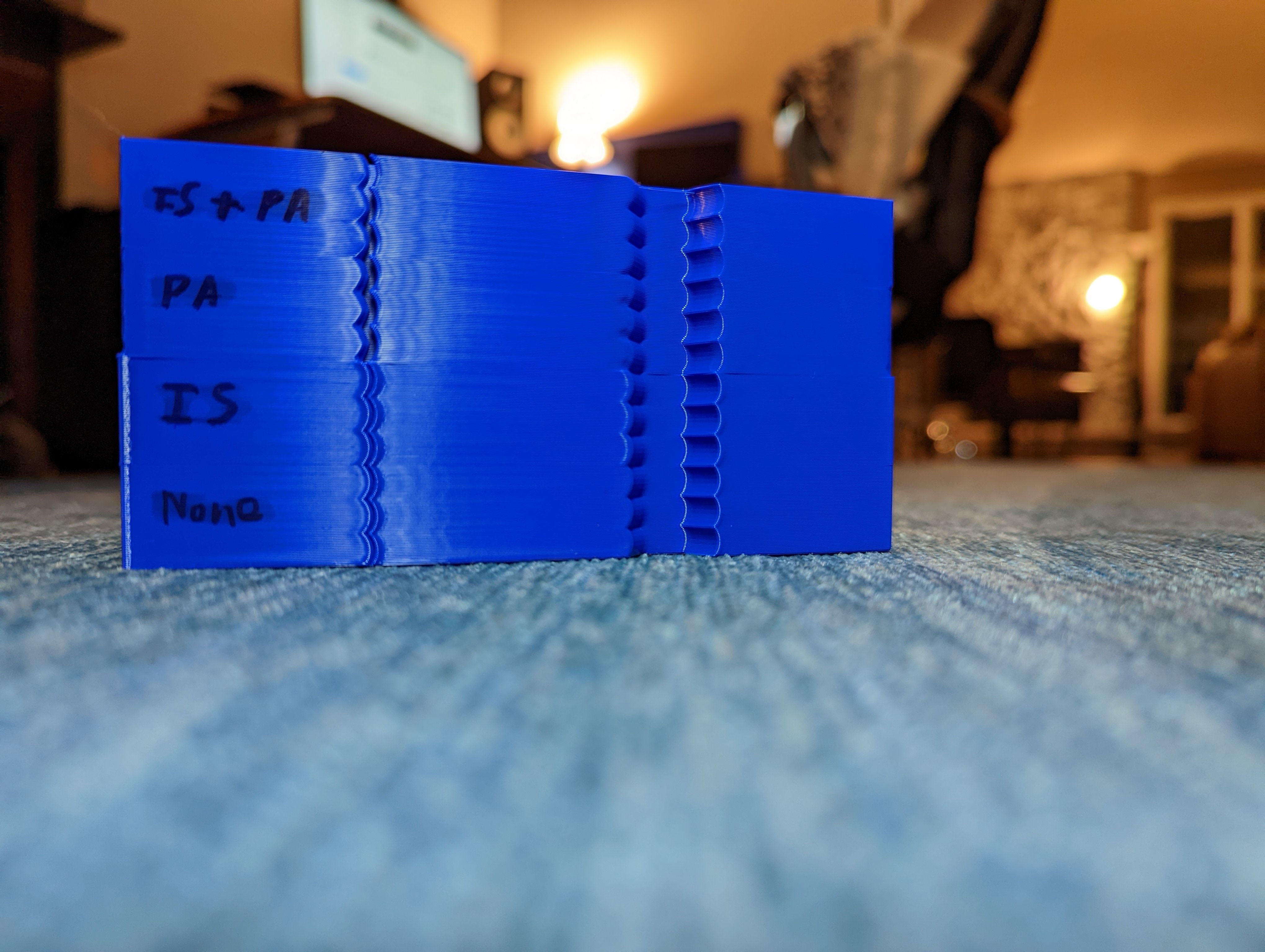
For comparison's sake, this print is with a direct mounted Orbiter V2 on the smart effector, 1-12k acceleration, 593 P"none":


There is barely any ringing visible even without IS active. With IS active it's gone up to 7k and barely visible up to 12k. The phenomenon on the small gap triangle cut is still there though, albeit you really need to look for it.
Could it be that the sandwich mount (3 arms Rapido holder and 3 point Orbiter/LGX standoff screwed together tightly helps the flex in the PCB?). I thought the additional weight of the Orbiter was counter productive, but right now I'm not so sure anymore. Linked a vid to it in another thread here 2 days ago: https://youtube.com/shorts/504USJkVbjc?feature=share
Might try to print something that "stabilizes" the hotend and re-test..
-
@dc42 I'd say I'm confident that the 50Hz figure is +/- 3Hz correct.
I measured it on every face in every orientation, with 1 ripple (100mms/~2.1mm) and up to 5 ripples that I could spot and mark with confidence (500/9.8). So the truth should be somewhere between 47 and 52 Hz.
I also ran the ringing tower at 75mms, 50mms to confirm the ripples grow / shrink linearly with speed. Also ran it at 200mms but they're too washed out to confidently measure them.
The strangest part of it all is that the amplitude (and also the amount of the ripples) gets worse when I remove the weight of the direct drive extruder. Which, after thinking about it could mean that I could try to lower my belt tension instead of increasing it. 47Hz was the more in the upper range of Gates' recommended tension for a 700mm span and at the upper range of Moon's recommended bearing load.
-
@bberger I found input shaping a little frustrating with my delta so good luck! I tuned out my ringing (37 Hz +/- 5 Hz for me), then i get the lip at the corners which is worse to me than the ringing. The only variable to fix that was taking my jerk above 40 mm/s (M205) ... at which point i get my ringing back. To lower the ringing after that i had to increase the amplitude of the IS... and then it sounds scary as the motors are doing their IS work... so I decided to shelve tuning it for a bit until i figure out what mechanical bit will need help.
-
@lord-binky said in Input Shaping - why (not effective on some parts at all):
@bberger I found input shaping a little frustrating with my delta so good luck! I tuned out my ringing (37 Hz +/- 5 Hz for me), then i get the lip at the corners which is worse to me than the ringing. The only variable to fix that was taking my jerk above 40 mms^2... at which point i get my ringing back. To lower the ringing after that i had to increase the amplitude of the IS... and then it sounds scary as the motors are doing their IS work... so I decided to shelve tuning it for a bit until i figure out what mechanical bit will need help.
I'm sorry, but I don't quite follow.
40mm/s jerk is seriously low, how are you printing curves with such a low setting? If I go below 480mm/s^2 my printer almost falls apart on curves.
If you mean 40mm/s^2 acceleration though that's also scary low.
Not sure which setting you are actually referring to as the unit used makes it a bit confusing..
Also: what do you mean with "increase the amplitude of the input shaper"? Did you set custom input shaping impulses?
-
@dc42 just spotted this thread (https://forum.duet3d.com/topic/27855/input-shaping-pressure-advance-artifact) which pictures my ringing behavior after that small gap section better than I could.
Basically gone everywhere (90deg corners and the bulge on the right hand side), but still very, very prominent after that gap section:
Different printer and kinematics, similar effect.
-
@bberger I had meant 40 mm/s (M205-> max instantaneous speed change in mm/sec or 3000.0 using M566). I don't think that's a low jerk setting. As for the input shaping M593 Snnn (optional) Damping factor of ringing to be cancelled, default 0.1. The way I read that is increase/decrease this if you know you nailed your frequency but input shaping is too much/little.
-
@lord-binky yeah, my bad. For some reason my head was stick at "40mm/min".
To follow up on my Klipper experiment:
- that ringing artifact I have on RRF on the ringing test print is completely gone on Klipper - completely ringing-free from 1k-12k with the same shaper (MZV @ 53Hz on both axis).
- ADXL measurements confirm 53Hz shaper freq (52.8Hz on X, 53.8Hz on Y, so I just set it to 53Hz for both) at 0,0,20mm (X,Y,Z) with my flying Orbiter v2
- use of EI shaper is indistinguishable from MZV
- I measure very similar frequencies across the majority build volume (it's +1.5/-1.5) within a radius of 150mm, with the nozzle 20mm above the bed
- I get a second frequency at the extreme edges of the bed, near tower and opposite tower (I think it's the magballs disconnecting at those points due to extreme angles: 0,-175,20 and 0,+175,20). Graph reads like something is lose, vibrations all over. Only starts outside of 150mm radius though.
Extras:
- with RRF I had some strange extrusion problems on rectangular infill when using input shaper and PA where it left gaps on the perimeters and failed to connect the infill consistently. I had to go below 150mms and ~1.5k acceleration to make that go away. This is completely gone in Klipper. Perfectly connected rectangular infill even at 400mm/s@10k.
Maybe there's something to look into to improve RRF in that regard. I for one would absolutely love that. Duet Hardware is top notch and I actually like RRF. Would love ot see it improve here.
-
-
This is another case of IS + PA causing issues, and of IS application being somewhat inconsistent.
Any progress @dc42 on the IS implementation?
My biggest issue with it right now is with the lack of application on short segments. Most of my prints have radiused corners, so IS doesn't get applied at all. This is also the case for the start of a circular outer perimeter, since those are short segments as well.
Maybe a look ahead could help "stitch" the IS application together across multiple small segments?
-
Here is an example of how a circular perimeter is effected, even with IS enabled and working well for square corners / large segments:
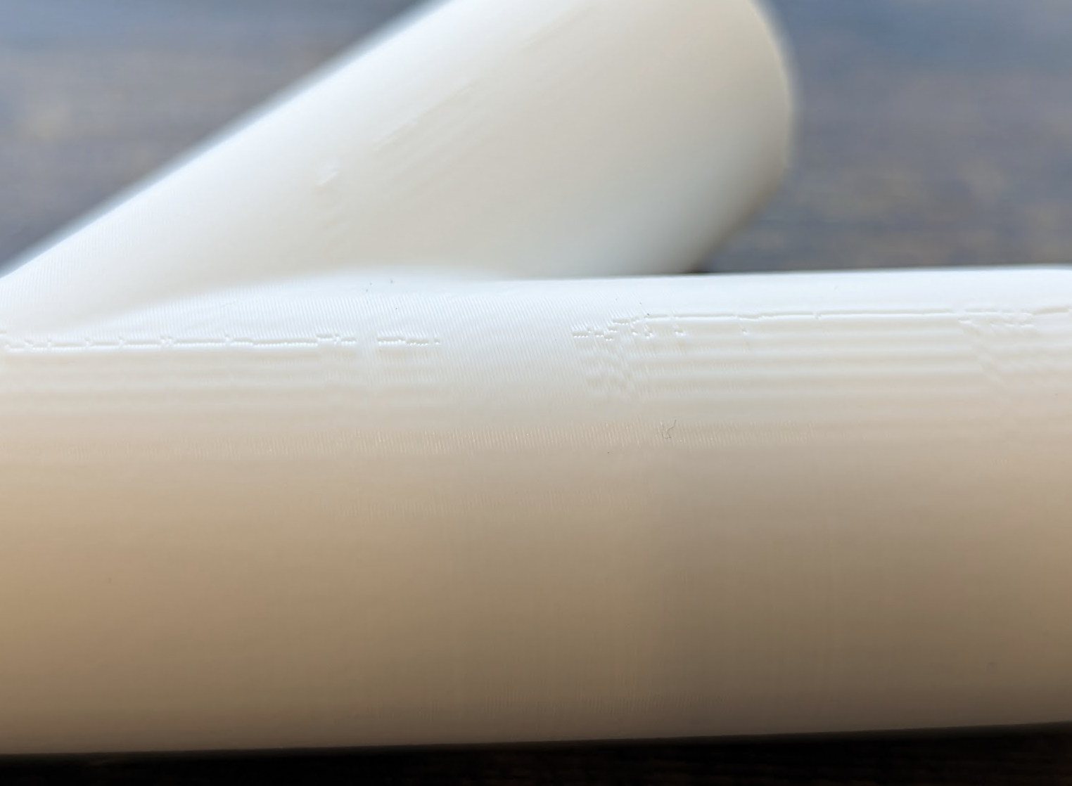
-
@CCS86 said in Input Shaping - why (not effective on some parts at all):
My biggest issue with it right now is with the lack of application on short segments. Most of my prints have radiused corners, so IS doesn't get applied at all. This is also the case for the start of a circular outer perimeter, since those are short segments as well.
We are looking at how to handle IS on short segments - its on the work list.