New heated enclosure printer
-
@coseng said in New heated enclosure printer:
For extruder calibration, is the 'mark and measure' or the 'extrude and weigh' a more accurate approach? Or another technique?
I think you're talking two separate things here.
Mark and measure would be for getting the steps per mm accurate so it's moving the correct amount of filament based on the motor and gearing anyway.
The extrude and weigh approach is more for testing the limits of flow, which is going to take melt rate, back pressure, slippage, etc into account.
Set the steps per mm at a low speed, and then set your flow rate for actual printing.
This is a pretty basic guide on establishing both and should let you find the limits of flow rate ballpark at least. https://duet3d.dozuki.com/Guide/Ender+3+Pro+and+Duet+Maestro+Guide+Part+4:+Calibration/40?lang=en#s165
-
@phaedrux I think you're talking two separate things here.
I meant comparing the weight of the extrusion of a 100mm feed command and 100mm of filament. Seems like either method could work. I'm going to focus on getting those print problems resolved before trying to go faster.
Do you think the print problems at the rib ends could be helped by using the pressure advance functionality? Maybe there is slightly too much material being extruded at these direction reversals, causing them to bunch up and fall over.
-
@coseng said in New heated enclosure printer:
Seems like either method could work.
Yes I see what you're saying now. I haven't compared the results of using either technique. It would be interesting to see how much the steps per mm would differ.
Yes if you aren't using pressure advance yet it would be a good idea to start. I don't know if it would solve the rib problem. It almost looks like dribble on a retraction move, or like Cura is still doing something stupid. It would help to see it in action while printing to see what is actually happening there.
The other thought about the ribs I had, is that you've designed them as if for an injection molded part. Perhaps rather than a thin rib, you could create a triangular profile instead.
-
It almost looks like dribble on a retraction move, or like Cura is still doing something stupid.
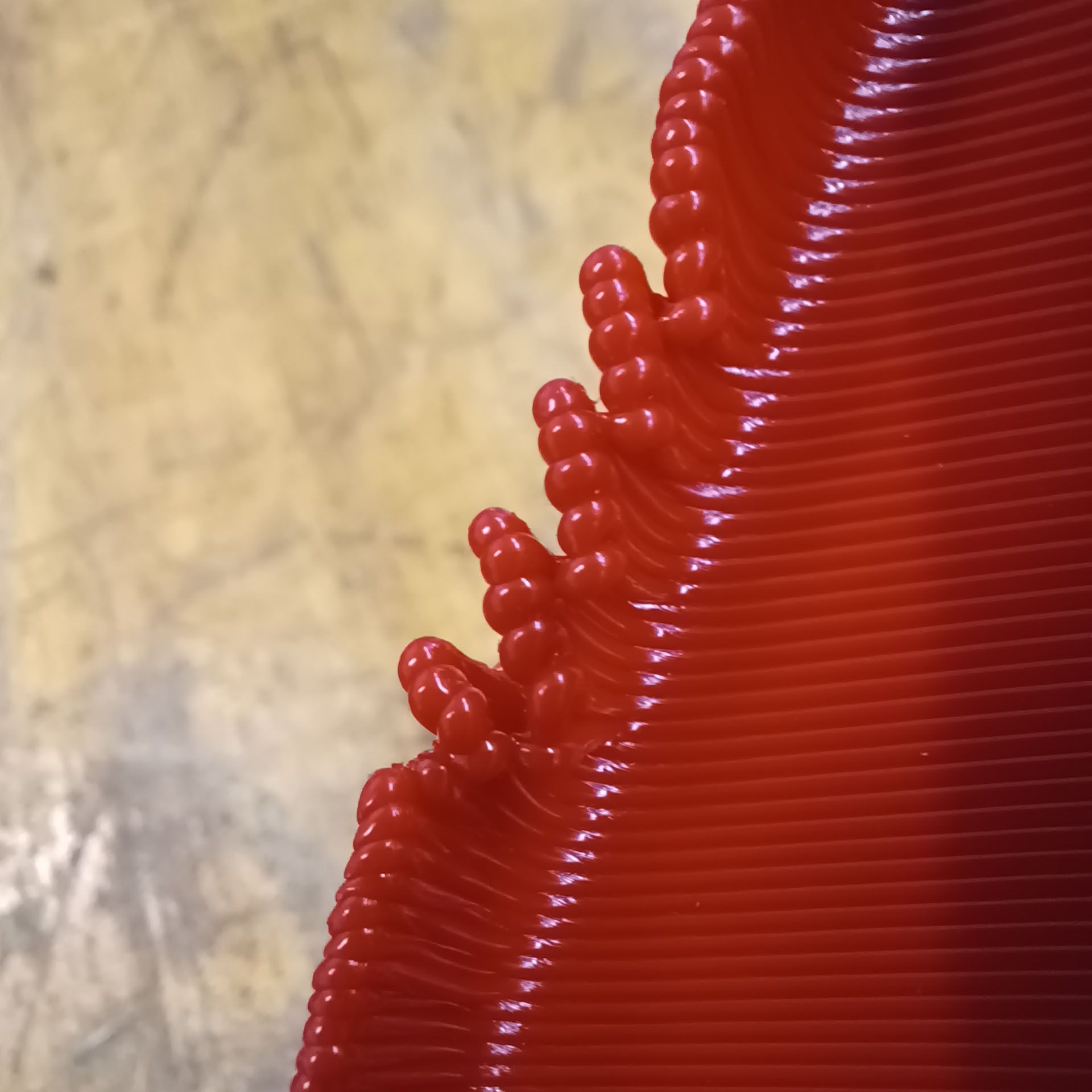
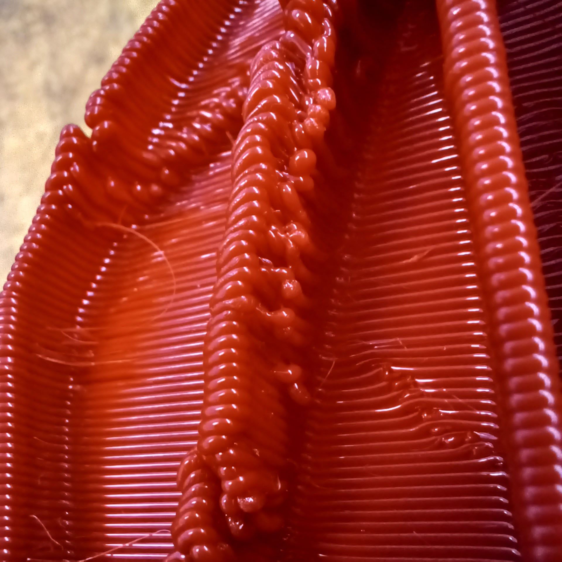
There are no retractions in those areas and the g code preview shows a clean toolpath with no weirdness, so I am thinking maybe overextrusion is causing there to be too many people in the bed and one falls off the edge. Up close, the extrusiuon bead is complete and consistent, just not in the proper place.
I turned pressure advance on with a console command halfway through this 0.8mm nozzle print and let's see if it makes a difference. The print speeds became a lot more variable so I also increased the extruder jerk value to 480, at which point it did not seem that much slower.
-
@phaedrux said in New heated enclosure printer:
The other thought about the ribs I had, is that you've designed them as if for an injection molded part. Perhaps rather than a thin rib, you could create a triangular profile instead.
Yes, that is one option but some of the ends of the part have similar geometry so would be hard to do there. I can try that on the rib ends where it is possible to reduce the possible places where it can happen.
-
OK, making some progress. This is the first 0.8mm nozzle part off the machine. 4hr3min print time, 0.4mm layer height. About halfway though the print I activated pressure advance with a 'M572 D0 S0.10' command.

The change did not eliminate the rib end wiggles, and in fact one wiggle that was already happening continued to happen.

There was a visible difference in the accuracy of the toolpaths, with the no-PA areas showing a better finish and more accurate toolpath than the areas with PA.


The two tall ribs with the triangular ends was where the accuracy difference was most apparent. It seems that the PA was causing a decent variation in the extruded line width. The no-PA areas were triangular and straight while the lines in the areas with PA were not straight and had some convexity to them. Looking at the top layer it seems that the lines were thinning at each end. Maybe the S0.1 was too much PA?I'm starting to wonder if the inertia of the extruded bead is causing it to flop over when the printhead changes directions quickly. Or something dynamical like that, since the gcode is clean and there do not seem to be obvious mechanical problems.
I think the next test is to add a layer fan to see if cooling them quicker will prevent the problems. Though I do have second thoughts about that approach, since looking at the close-ups in the previous post it seems that there is just too much material being printed for the layers to stack on each other cleanly. They seem to be all jumbled together with no room for proper placement. But on the areas without such an abrupt direction reversal the layers are stacking very cleanly, so is it only on those areas with an abrupt change in direction. Weird.
-
You'll need to tune the amount of pressure advance used. It's not as simple as turn it on and go.
https://docs.duet3d.com/en/User_manual/Tuning/Pressure_advance
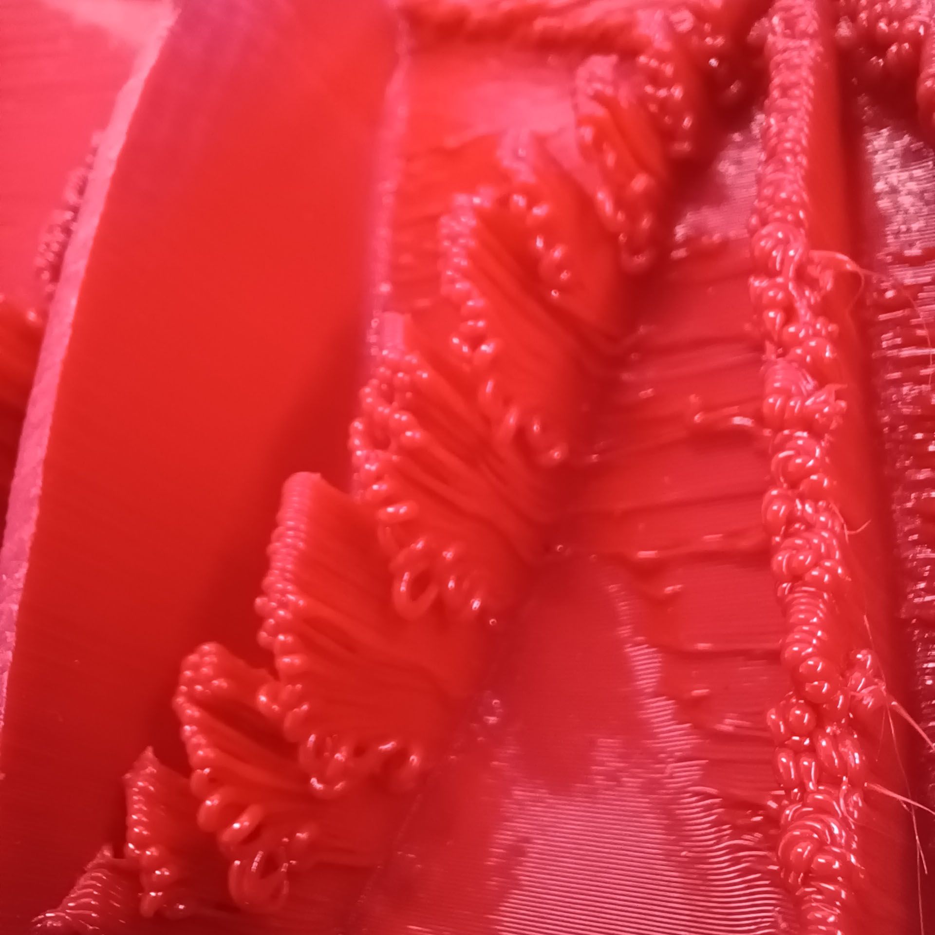
Adding a layer fan would be a good idea. The ends look like they are just squirting out into thin air and once it starts, the layer that comes above it has nowhere to attach to, so it just spirals upward.
-
@phaedrux I think that activating pressure advance did not make an improvement to the main problem at hand, so in the interest of not trying to tweak too many variables at once, will turn it off and try a layer fan first. If the fan does not do it, both can be done and then will have a full data set for comparison.
-
Last night I made some modifications to the part to see how much of the thin wall nature is the issue. I thickened the part to about 20mm and sliced it with a 0.8mm nozzle, 0.4mm layer, 20% gyroid infill and 2 walls. The result was the best yet, with a 5hr3min print time.

I'm really happy with the surface finish and if this last issue can be resolved will consider the printer a complete success.

Though the same problem happened along one of the inner edges.

The narrow ribs with no triangular ends (done to try to make the problem happen) printed great, through they did show signs that pressure advance could be beneficial. Most of the wall was 2.8mm thick, but it fattened up to a teardrop shaped 3.5mm bulge at the end.

Now to install the layer fan and duct and run the same file again, modified to turn the fan on after 100 layers.

Chris
Cosentino Engineering -
@coseng said in New heated enclosure printer:
Could you upload the gcode for this print? Would like to take a peek and see whats going on there.
-
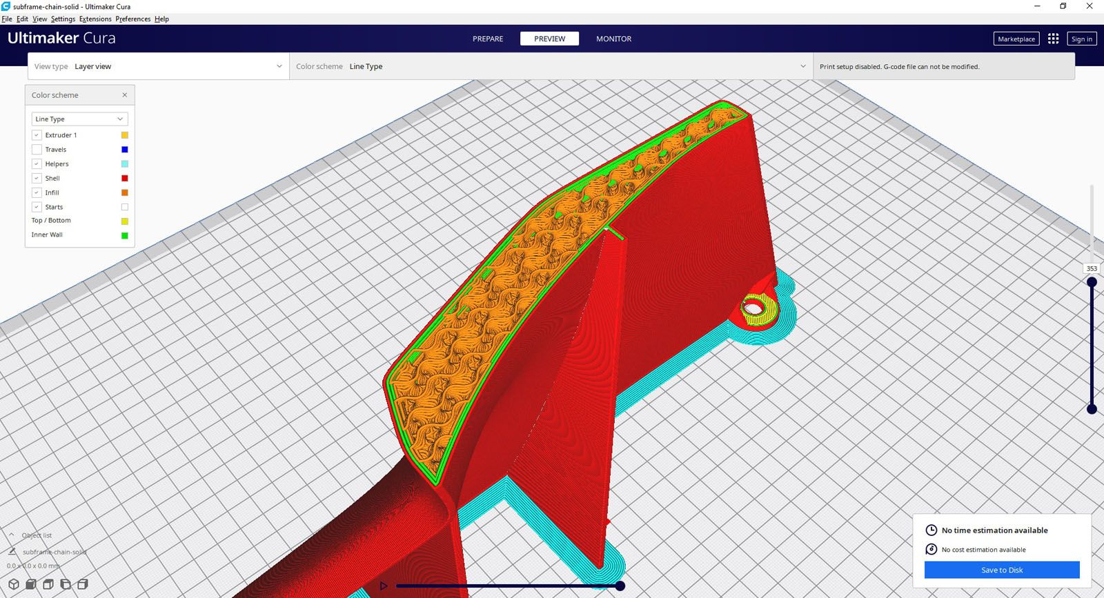
@sebkritikel Here's a screenshot of the area. The problem area is the sharp vertex in the forground. The gcode is 28MB, where would I upload it to here?
-
@coseng That duct looks pretty restrictive for an axial fan.
-
@phaedrux Well rev1 did not fit because I did the bellows mounting on the fly and was not in the CAD model! So I'll make rev2 bigger.
-
Do you have a radial blower fan for more static pressure?
-
@phaedrux I was thinking it would not need significant amounts of air, but I good point, why underestimate? Let me see what I have in the back with some more oomph.
-
@sebkritikel said in New heated enclosure printer:
Could you upload the gcode for this print? Would like to take a peek and see whats going on there.
https://drive.google.com/file/d/1bjFQm2guAu9zjHL3NyoJ2kZlp8FMA5ES/view?usp=sharing
Here it is zipped.
-
@coseng Thank you!
I was trying to see if any of Cura's coasting settings were configured, but nope, the gcode looks pretty good. You're printing ABS right? In the specific image I quoted, I think a small amount of part cooling could be beneficial - taking into account the slight overhang you're printing combined with the corner segments and movement speed. I'd guess the material is peeling back during those segments.
I've found ABS doesn't need as extreme of cooling as PLA does at similar feed rates. Really, ABS does quite well without cooling, but a small amount has helped me solidify my overhangs+corner sections.
Your general surface finish is much improved - I try to print my inner walls first, followed by my outer walls, and then my infill segments- helps me avoid any infill bleed-through (I do allow for some infill overlap with my inner walls in Cura).
For pressure advance, there are a few good calibration macros (that allow you to set your PA range, line segment lengths+speeds), but I find the best values there are a hair conservative. Try printing the Klipper ringing tower (maybe a few bottom layers, but otherwise inner and outer walls only - no infill or top surface layers), sweeping across PA values (starting with 0, ending with a fairly high value). A good area to look at is this section:
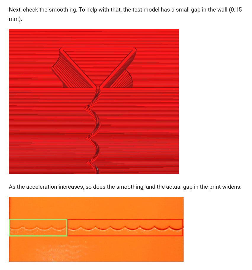
While that doc is detailing input shaping, you'll see (and feel) the PA impacts on the areas indicated by green and red. -
@sebkritikel OK, thanks for the info. This part just ran overnight, 5hr35min, and I think came out quite good. It is definitely better than the thin wall version and not much heavier and a lot stiffer. The problem is this technique is not applicable to all of the parts. I will do it when possible, but will dedicate today to running some of these calibration processes in the hope of getting both types of parts running well.


Instead of the ribs of the previous runs, this is modeled as solid with some cutouts for the mounting holes.


There are a few printing artifacts and hopefully today's activities will help to address them, but I'm very happy with these very usable parts.
-
Made and ran a PA test part with geometry similar to my problem areas. This part's toolpaths are one continuous pass per layer, no infill, retractions, etc. 0.8mm nozzle, 0.5mm layer height. 135mm/sec actual print speed.

It printed mostly great, with the exception of one area:

The location of this problem points strongly to thermal issues of the extrusion bead cooling, so next on deck is the layer fan.
The PA test changes were subtle and easier felt with your fingertips and not a camera. Best value seems to be 0.03 where there was the least amount of bulging at the rib ends but no other weirdness at corners and transitions.

Progress!
-
@dc42 I'm having a little trouble in paradise this evening. I was about to install the layer fan and had modified the system.cfg file to add the two lines for fan definition, and noticed the DWC with the wired internet connection was acting sluggishly. I made an error with the config.sys file in not changing the numbers from 3 to 4 to add the fan. I updated the file by changing those two lines, and I clicked reboot mainboard for the updated config.sys file and presto, the web browser could not reconnect with the printer.
I did the 'ol printer reboot, and then the paneldue partially booted but had 'connecting' in the upper right corner and the bed temps and other displays were not present and I still had no ethernet connectivity. I did another reboot and the paneldue now did not display anything, just blank with the backlight on.
Windows says that nothing is plugged in to the internet port and none of the ethernet plug lights are on on either end.
Before I started messing around and doing something stupid, I was hoping for a little guidance.