Duet3D Logo Duet3D
    • Tags
    • Documentation
    • Order
    • Register
    • Login

    Orbiter 2 extruder mounting for Smart effector with Magball arms

    Scheduled Pinned Locked Moved
    Smart effector for delta printers
    12
    56
    5.6k
    Loading More Posts
    • Oldest to Newest
    • Newest to Oldest
    • Most Votes
    Reply
    • Reply as topic
    Log in to reply
    This topic has been deleted. Only users with topic management privileges can see it.
    • dc42undefined
      dc42 administrators @tecno
      last edited by

      @tecno said in Orbiter 2 extruder mounting for Smart effector with Magball arms:

      @dc42
      Will you want to keep 55mm c/c on balls or go a bit wider there also?

      Go wider.

      Duet WiFi hardware designer and firmware engineer
      Please do not ask me for Duet support via PM or email, use the forum
      http://www.escher3d.com, https://miscsolutions.wordpress.com

      tecnoundefined jay_s_ukundefined 2 Replies Last reply Reply Quote 1
      • tecnoundefined
        tecno @dc42
        last edited by

        @dc42

        Good, like that approach a lot. You should also have a look at Phaetus 4-screw mounting of the hotend.

        1 Reply Last reply Reply Quote 1
        • jay_s_ukundefined
          jay_s_uk @dc42
          last edited by

          @dc42 yes, definitely look at supporting mounting a dragon or dragonfly hotend

          Owns various duet boards and is the main wiki maintainer for the Teamgloomy LPC/STM32 port of RRF. Assume I'm running whatever the latest beta/stable build is

          tecnoundefined 1 Reply Last reply Reply Quote 0
          • tecnoundefined
            tecno @jay_s_uk
            last edited by

            @jay_s_uk @dc42

            Not via adapter as I have today! We must get rid of the E3D style big hole that can not lock the hotend!

            1 Reply Last reply Reply Quote 1
            • weed2allundefined
              weed2all
              last edited by weed2all

              This is my take for direct extruder sherpa mini

              [url=https://ibb.co/jh3q5yK][img]https://i.ibb.co/zsPC5Xc/20220717-113347.jpg[/img][/url]
              [url=https://ibb.co/3Mvh1hX][img]https://i.ibb.co/P9MCxCp/20220717-113353.jpg[/img][/url]
              [url=https://ibb.co/HGjsNyM][img]https://i.ibb.co/r5VSbhL/20220717-113358.jpg[/img][/url]
              [url=https://usefulwebtool.com/math-keyboard]subscript in math[/url]

              1 Reply Last reply Reply Quote 0
              • weed2allundefined
                weed2all
                last edited by weed2all

                This post is deleted!
                1 Reply Last reply Reply Quote 0
                • Adrian52undefined
                  Adrian52 @vapvap
                  last edited by

                  @vapvap I have just added it to the thingiverse thing 5402227

                  vapvapundefined 1 Reply Last reply Reply Quote 1
                  • Adrian52undefined
                    Adrian52 @dc42
                    last edited by

                    @dc42 I find an extra 12mm allows the orbiter 2 to be mounted horizontally with a minimal vertical filament path between extruder and hotend, whilst maintaining the 55mm arm separation. I find the 55mm separation works well - you don't have to modify carriages, and the performance seems fine. I have been printing at 250mm/sec, with travel at 300mm/sec.

                    1 Reply Last reply Reply Quote 0
                    • vapvapundefined
                      vapvap @Adrian52
                      last edited by

                      @adrian52 Thanks a lot.
                      What plastic do you use/recommend for this part?

                      Adrian52undefined 1 Reply Last reply Reply Quote 0
                      • Adrian52undefined
                        Adrian52 @vapvap
                        last edited by

                        @vapvap it works OK with PLA, although I am currently printing a set in nylon - will report if I can see a difference.

                        1 Reply Last reply Reply Quote 1
                        • Snimaxundefined
                          Snimax @dc42
                          last edited by Snimax

                          @dc42 I've made a quick and dirty model approximating how big the smart effector would need to be for me to be able to mount an Orbiter directly on-top of where the bolt is. With my specs it would need to be a distance of around 71.3 mm between the ball studs. I've angled the extruder by 15 degrees to make it take slightly less space in between the arms.

                          The cones visualize the maximum reach of the arms for my delta with a 350mm bed and 440mm arms.

                          6f9ddd6f-1f4d-418b-95db-88428b994e1f-image.png

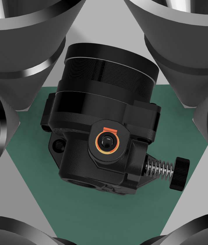
                          Its probably possible to make it an even tighter fit by tweaking the parameters but I thought it was good enough to continue the discussion ¯\(ツ)/¯

                          dc42undefined Adrian52undefined 2 Replies Last reply Reply Quote 0
                          • dc42undefined
                            dc42 administrators @Snimax
                            last edited by

                            @snimax thanks, that's very useful. Did you leave the spacing between adjacent ball studs in the corners the same, or did you increase that too?

                            Duet WiFi hardware designer and firmware engineer
                            Please do not ask me for Duet support via PM or email, use the forum
                            http://www.escher3d.com, https://miscsolutions.wordpress.com

                            Snimaxundefined Adrian52undefined 2 Replies Last reply Reply Quote 0
                            • Adrian52undefined
                              Adrian52 @Snimax
                              last edited by

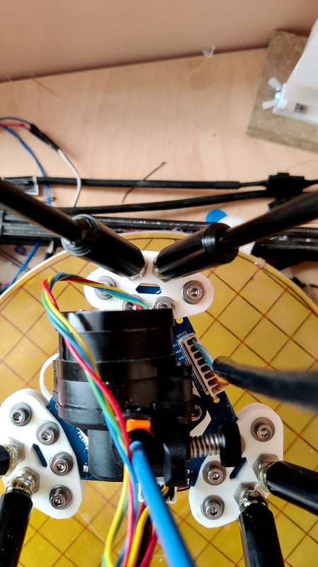
                              @snimax tried to take a picture of my version from the same viewpoint
                              alt text

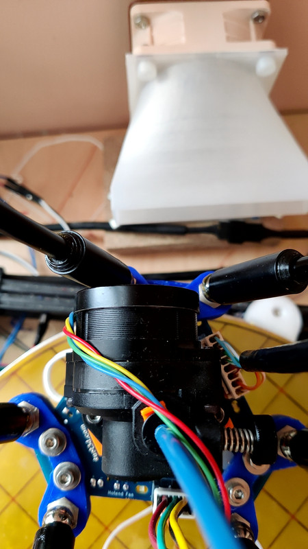
                              I have maintained the 55mm spacing, and find a good fit with the motor orientated as shown. The effector is in its furthest 'Y' position, where the arms are closest to the motor.

                              1 Reply Last reply Reply Quote 0
                              • Snimaxundefined
                                Snimax @dc42
                                last edited by

                                @dc42 I tried to keep the spacing between the balls at the corners. I think there was a formula somewhere of the stability of the effector where you wanted to keep that spacing short but I cant recall where I saw it 😕

                                @Adrian52 Looks good! I like the idea of having a straight and much shorter filament path, compared to my adapter where the filament is in a slight s-shape 🙂 Haven't gotten around to compare it yet though

                                1 Reply Last reply Reply Quote 0
                                • Adrian52undefined
                                  Adrian52 @dc42
                                  last edited by

                                  @dc42 I have now done an adapter that maintains the 12mm spacing of the magballs

                                  alt text

                                  The carriage adapters look like this

                                  alt text

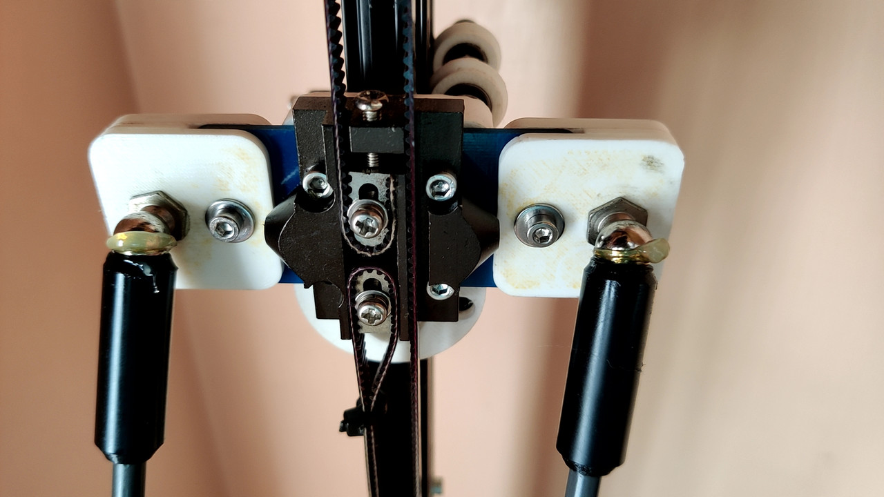
                                  I played with the offset, settling on moving the centre line of the studs 7.5mm from the base of the triangle. This gives very close (within 0.02mm) spacing of 81mm for the arms, requiring a 13mm spacer on each side of the carriage. As you can see, this gives plenty of room for the orbiter 2 mounted with a straight vertical filament path.

                                  I have printed these in nylon using 80% infill, which seems to give a slightly better result than PLA .

                                  Not much experience printing with this setup yet, but the initial impression is of increased precision over the 55mm arm separation.

                                  dc42undefined vapvapundefined 2 Replies Last reply Reply Quote 1
                                  • dc42undefined
                                    dc42 administrators @Adrian52
                                    last edited by dc42

                                    @adrian52 thanks. Wider arm spacing is generally preferred, because it provides greater rigidity and less sensitivity to small geometric errors.

                                    Duet WiFi hardware designer and firmware engineer
                                    Please do not ask me for Duet support via PM or email, use the forum
                                    http://www.escher3d.com, https://miscsolutions.wordpress.com

                                    Adrian52undefined 1 Reply Last reply Reply Quote 0
                                    • Adrian52undefined
                                      Adrian52 @dc42
                                      last edited by

                                      @dc42 I should have done my homework. According to the reprap wiki here , stability decreases linearly with ball gap, but increases with the square of arm gap. So compared to the standard geometry, keeping the arm gap decreases stability almost threefold, whilst the 12mm ball gap with wider arms more than doubles stability. I think I was so impressed with the improvement of direct drive over the bowden that I didn't consider the effect of geometry on stability.

                                      1 Reply Last reply Reply Quote 0
                                      • vapvapundefined
                                        vapvap @Adrian52
                                        last edited by

                                        @adrian52 As always, great idea!
                                        And as usual - we are waiting for the addition to "thingiverse".

                                        Adrian52undefined 1 Reply Last reply Reply Quote 0
                                        • Adrian52undefined
                                          Adrian52 @vapvap
                                          last edited by

                                          @vapvap Thanks. Posted it now

                                          https://www.thingiverse.com/thing:5463328

                                          vapvapundefined 1 Reply Last reply Reply Quote 1
                                          • vapvapundefined
                                            vapvap @Adrian52
                                            last edited by

                                            @adrian52 Thank you so much for sharing your ideas with us.
                                            Do you do any additional fine-tuning in the firmware?

                                            1 Reply Last reply Reply Quote 0
                                            • First post
                                              Last post
                                            Unless otherwise noted, all forum content is licensed under CC-BY-SA