Issues with pressure advance since RRF 3.4
-
@dc42 Could you share any of your test methods? Im currently just plotting step/dir signal outputs.
-
I've been debating whether or not to comment on this thread for weeks as I'm hesitant to blame PA for the print artifacts I've been seeing, but after a lot of testing it seems to be the culprit. It's possibly I'm still getting through some acceleration/jerk tuning stuff or I still need to play with belt tension and/or IS. However, since going from 3.3 to 3.4 on my voron 2.4 build with a Duet wifi 2, I have been seeing odd bulging behaviors on roundish perimeters, or with embossed text. I can post some pictures later of some examples. I sometimes see sections that are supposed to be straight end up with a gentle concave curve.
Again, it could be that I'm just new to tuning Core XY systems, or my external stepper driver setup not being super robust, or something else entirely, but it feels like I've spent a lot of time working out print artifacts on this machine to get close to what I'd consider a perfect FDM part.
-
@michaelr123 I am interesting in seeing any differences in the effects of pressure advance between RRF 3.3 and RRF 3.4.x with input shaping not used. [There is a separate discussion on the interaction of PA with IS.] Ideally with a quick-to-print example (e.g. just a few layers high) that demonstrates the difference.
Duet WiFi hardware designer and firmware engineer
Please do not ask me for Duet support via PM or email, use the forum
http://www.escher3d.com, https://miscsolutions.wordpress.com -
@dc42 totally understand, we need to narrow down whether it's 3.3 to 3.4 that causes issues for PA specifically. I think my comments are more along the lines of it's been tricky to tune a coreXY on 3.4 so far. I need to try rolling back to 3.3 yet as I've been on 3.4 for awhile now.
-
@dc42 said in Issues with pressure advance since RRF 3.4:
Ideally with a quick-to-print example (e.g. just a few layers high) that demonstrates the difference.
I notice the difference with a simple hollow cube with 2mm thick walls. The corners bulge more in 3.4 and the extruder sounds different. I had to lower e jerk to prevent gaps and reduce the noise. e jerk went from 3000 to 1500. PA only 0.025.
-
Now things are getting complicated.
I have another printer which is a Bear Bondtech Mk3 bedslinger (originally was a Prusa Mk3s).
When I compare corners with RRF3.3 to RRF 3.4 there are hardly any differences. RRF 3.3 is a bit better but RRF 3.4 is not as worse as my previous results with the CoreXY (Voron 2.4) machine.So what's different between those two printers.
The printer (Voron 2.4) having difficulties with bulging corners and RRF 3.4 differs in three things compared to the Bear Mk3:- it's a Core XY machine
- prints perimeter double the speed
- uses a Duet 1LC toolboard V1.2
Maybe this helps somehow...
-
@argo it's entirely possible that there could be a bug that affects PA when the extruder is driven by a CAN-connected expansion board that is not present when it is driven by the main board, because different code is used. I will do some more tests with the extruder driven by a tool board.
Yesterday I did comparative tests between 3.3 and 3.4 using 120mm/sec perimeters, 160mm/sec infill and PA 0.4. The results were very similar. Extruder was driven from the Duet 3 Mini.
Duet WiFi hardware designer and firmware engineer
Please do not ask me for Duet support via PM or email, use the forum
http://www.escher3d.com, https://miscsolutions.wordpress.com -
I bet your to-do list is quite full and time is limited but when you find the bug and did a possible fix to the firmware feel free to upload the compiled firmware for me/us for testing.
I've seen you did this before and uploaded the files to a Dropbox folder. -
Results are still unchanged with RRF 3.4.2rc2.
PLA, PA set to 0.057:
-
@argo please can you provide a small GCode print file that demonstrates the issue, along with the config.g file for the machine concerned, and details of the extruder (especially the length of the Bowden tube). A print file that does the print in the photo you posted above (and stops after a few layers as in the photo) would be suitable.
Duet WiFi hardware designer and firmware engineer
Please do not ask me for Duet support via PM or email, use the forum
http://www.escher3d.com, https://miscsolutions.wordpress.com -
Yes, sure.
Extruder is a LGX (not the lite version) with a Rapido HF Hotend.
The bowden tube length between the extruder gears and the hotend is about 15-20mm long.
Printer: Voron 2.4 - 300mmPhoto of the printer:
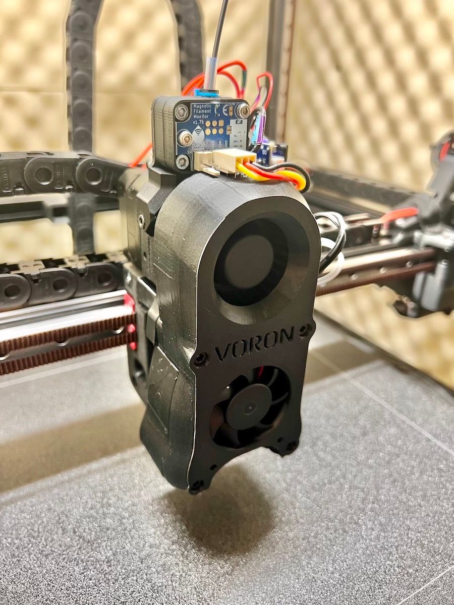
Config.g:
G4 S1        ; wait 1s for expansion boards to start

; General preferences
G90                                         ; Send absolute coordinates...
M83                                         ; ...but relative extruder moves

; Network
M550 P"Walross"                        	; Set machine name
M552 S1                                     	; Enable network
;*** Access point is configured manually via M587
M586 P0 S1                                  ; Enable HTTP
M586 P1 S1                                  ; Disable FTP
M586 P2 S1                                  ; Disable Telnet
M575 P1 S1 B57600							; Panel Due

; Printer geometry
M669 K1                	                    ; Select CoreXY mode
M208 X0:290 Y-3:300 Z-0.2:270              ; Axis Limits
M564 H0							            ; allow unhomed movement

;------- drives from top---------------------------------------------------
;  B -------+------ A
;   | P.02 | P.03 |
;   -------+-------  Z-Drives
;   | P0.1 | P0.4 |
;   -------+-------
;        Front

; Drive Mappings
M569 P121.0 S0 D2                             ; Drive 0: E Axis
M569 P0.1 S1 D2                             ; Drive 1: Z-LeftFront Axis
M569 P0.2 S0 D2                             ; Drive 2: Z-LeftRear Axis
M569 P0.3 S1 D2                             ; Drive 3: Z-RightRear Axis
M569 P0.4 S0 D2                             ; Drive 4: Z-RightFront Axis
M569 P0.5 S1 D2                             ; Drive 5: Expansion: B motor (X-axis)
M569 P0.6 S0 D2                             ; Drive 6: Expansion: A motor (Y-axis)


; Motor remapping for dual Z and axis Limits
M584 X5 Y6 Z1:2:3:4 E121.0                              ; Motor mapping
M671 X-60:-60:360:360 Y-10:370:370:-10 S20	        ; Z leadscrews positions Left Front - Let Rear - Right Rear - Right Front

; Microstepping and Speed
M350 X32 Y32 E16 Z32 I1                     ; Configure microstepping with interpolation
M92 X160.00 Y160.00 Z800.00 E400.00         ; Set steps per mm	1.8 motors

; Speeds, Acceleration and Jerk
M566 X300.00 Y300.00 Z25.00 E400.00 P1          ; Set maximum instantaneous speed changes (mm/min)
M203 X24000.00 Y24000.00 Z900.00 E1200.00       ; Set maximum speeds (mm/min) ; SpreadCycle
M201 X5000.00 Y5000.00 Z1000.00 E5500.00        ; Set accelerations (mm/s^2) ; SpreadCycle

; Motor currents
M906 X1250.00 Y1250.00 Z1100.00 E700.00 I55        ; Set motor currents (mA) and motor idle factor in percent
M84 S30                                            ; Set idle timeout

; Endstops for each Axis
M574 X2 S1 P"io1.in" 				; Set X endstop controlled by switch
M574 Y2 S1 P"io2.in"                      	; Set Y endstop controlled by switch
M574 Z1 S2                                           ; Set endstops controlled by probe "OLD" VINDA
;M574 Z1 S1 P"io6.in"						; Z endstop switch

; Stallgaurd Sensitivy (maybe use to pause print after crash)
M915 X S2 F0 H200 R0		                ; Set X axis Sensitivity  1.8 motors
M915 Y S2 F0 H200 R0		                ; Set y axis Sensitivity  1.8 motors

; Input Shaper and Accelerometer
;M955 P121.0 I05 ;Accelerometer
;M593 P"zvdd" F46 S0.05

; Z-Probe
M558 P8 C"121.io2.in" I1 H2 F250:100 T6000 A500 S0.0025	; VINDA

; Mesh Grid
M557 X5:260 Y30:250 P7                         ;

; Z Probe Offset (Probe behind Afterburner)
;G31 P1000 X0 Y25 Z1.095	; VINDA - 3Djake Nano
G31 P1000 X0 Y25 Z0.770		; VINDA - 3DSWay Textured


; Filament Runout sensor
M591 D0 P3 L25.95 E3 R10:250 C"121.io1.in" S1		 		; Filament Sensor

; Heatbed Heaters and Thermistor Bed
M308 S0 P"temp0" Y"thermistor" T100000 B4725 C7.060000e-8       ; Heatbed Thermistor
M950 H0 C"out0" T0 Q10					                        ; Creates Bed Heater (SSR)
M307 H0 R0.889 K0.762:0.000 D3.02 E1.35 S0.6 B0
M140 H0										                    ; Bed uses Heater 0
M143 H0 S116                                                    ; Set temperature limit for heater 0 to 115C Bed

; HotEnd Heaters and Thermistor HotEnd
M308 S1 P"121.temp0" Y"thermistor" T100000 B4725 C7.06e-8     	; define E0 temperature sensor
M950 H1 C"121.out0" T1 Q100					                            ; Create HotEnd Heater
M307 H1 R4.568 K0.683:0.000 D4.04 E1.35 S1.00 B0 V24.4				; PID as heater
M143 H1 S295                                                    	; Set temperature limit for heater 1 to 285C HotEnd
M302 S15 R15														; min extrusion (cold extrusion) temp

; Fans Hotend + Part
M950 F3 C"121.out1" Q100				; Creates HOTEND Fan
M106 P3 T65 L1.0 X1.0 H1                 ; HOTEND Fan Settings
M950 F0 C"121.out2" Q100				; Creates PARTS COOLING FAN
M106 P0 H-1                         ; Parts Cooling Fan

; Fans Electronic compartment & Exhaust
M950 F1 C"out3" Q100				    ; Creates Case Fan 1
M106 P1 T40 S170 L170 X170 H0                 ; Case Fan 1 Settings
M950 F2 C"out4" Q100				    ; Creates Case Fan 2
M106 P2 T40 S170 L170 X170  H0                  ; Case Fan 2 Settings
M950 F5 C"out5" Q100				    ; Creates Exhaust Fan
M106 P5 T82 S150 L150 X150 H0                  ; Exhaust fan

; Chamber Thermistor
M308 S3 P"temp1" A"Chamber" Y"thermistor" T100000 B4725 C7.060000e-8     	; define chamber sensor

; Tools
M563 P0 D0 H1 F0                            ; Define tool 0
G10 P0 X0 Y0 Z0                             ; Set tool 0 axis offsets
G10 P0 R0 S0                                ; Set initial tool 0 active and standby temperatures to 0C
And the generated gcode and stl file (print time 9 min max):
Test.gcode
TEST.stl -
I did a esteps calibration today to rule out any extruder calibration issues.
Though Bondtech states it's not necessary, I wanted to be sure that esteps are spot on.
Turns out esteps are within 1-2% accuracy. So the extruder does work as intended.What else should I (double) check to rule out hardware issues? I mean, only 3 people so far in this thread confirmed PA issues out of 1000+(?) RRF users. That is peculiar.
-
@argo I have been meaning to do a test between the two firmware versions for a few weeks now and finally got a chance to do so on the weekend.
I have two identical cartesian bedslinger machines both running everything directly off a MB6HC with SBC. One is running on version 3.3 and the other is running on version 3.4.0. I am not presently using input shaping. Both machines have direct drive Titan Aqua extruders.
I printed a 50mm single outline square with a 1mm gap in one side, so that I can measure line starts and ends as well as seeing what happens at the corners of the print. I used a PA setting of 0.055 using ABS at a print speed of 45mm/s for both machines and a retraction of 0.4mm.
I did not see a difference between the two firmware versions, either at the corners or at line starts or ends. This was determined by measuring the difference in thickness at line starts and ends as well as the first corner vs the thickness midspan between the line start and the first corner. In each case I measured the same difference.
Based on some of your earlier comments and those from @dc42 it seems therefore that this problem may be confined to systems running with an attached tool board. Did you see any difference in printing when both machines were running on version 3.3 firmware? If not, then you can pretty much eliminate the mechanical hardware difference between the two machines as a cause of the problem.
-
Thanks for testing as well.
My bed slinger is not affected by this issue. RRF 3.3 and 3.4 look identical, though I find with RRF 3.4 and enabled input shapers, PA can’t be tuned to get as sharp corners as with 3.3.As with the CoreXY machine (+Duet 1LC and Bondtech LGX extruder) RRF 3.3 does look better than RRF 3.4 (both disabled IS). But even the RRF 3.3 results with this machine do not look as good as with the bed slinger.
I can’t remember I was having PA issues with this machine in the past. Only thing that changed was the Duet 1LC. And I don’t know what hardware issue may cause this as its only affecting corners and not infill lines. -
To rule out the extruder I changed from a Bondtech LGX extruder to a LDO Orbiter 2.0.
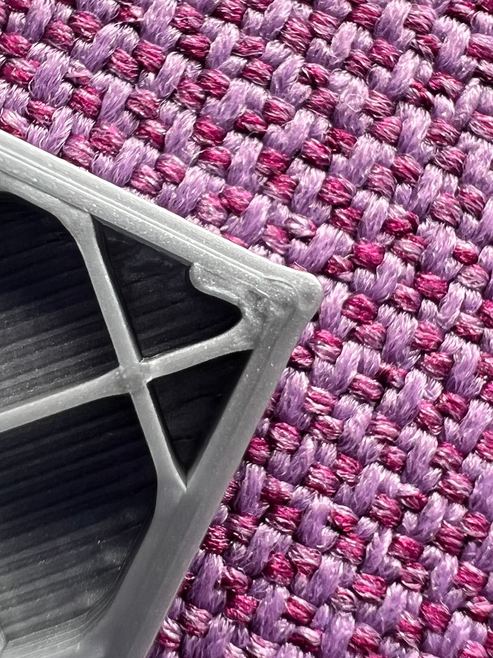
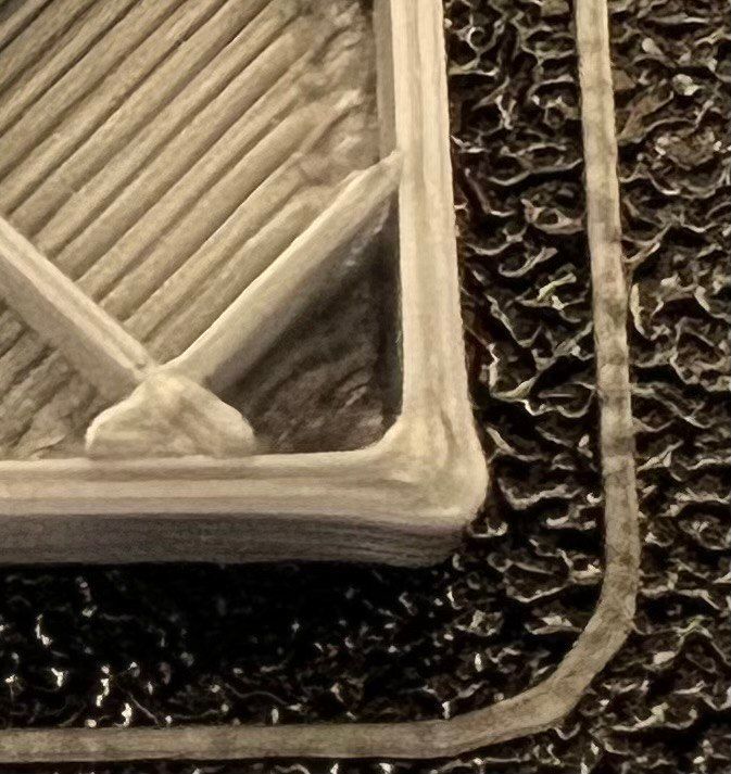
The Orbiter has almost no backlash and also has a shorter tube between gears and hotend compared to the LGX.Printing PLA, PA was set to 0.055 which usually is a good value for PLA and a direct drive extruder. The result is more or less the same. Infill lines do look fine and string but corners are bulging:
-
@argo Based on everything you've written, the most logical conclusion still seems to be that there may be a problem with RRF 3.4 running with the toolboard. Nevertheless there is one thing that caught my attention and which I think is worth looking into before trying to go further down the rabbit hole as this may be exacerbating (if not causing) the problem.
Looking at your print settings further back in this thread I see that you are running accelerations of 2000mm/s^2 for perimeters and 5000mm/s^2 for infill together with speeds of 160mm/s for perimeters and 250mm/s for infill.
If the equation shown on the old PA dozuki page is still used for pressure advance then the actual amount of advance is dependent on both the PA factor as well as the acceleration setting used. This means that for the same PA factor your two different accelerations (for perimeters vs infill) will give correspondingly different amounts of actual advance. Calculating the actual amount of advance resulting from your settings under the two different scenarios shows that you will have an increase in PA amount that is almost in direct (linear) proportion to the higher speed you are using for your infill vs the perimeter. However, as the plastic is non-newtonian in nature the relationship between print speed and required amount of advance will not be linear and that may be the reason why you cannot find a PA setting that works for both the corner as well as the infill.
Looking at your last print above it seems that you still have too much advance for your infill (line starts are very thick whereas line ends are excessively thin right at the end) but yet not enough for the perimeters (bulging at the corners).
I would suggest to try tuning your PA factor to the correct amount required for your perimeters (to get a sharp corner) and then tuning the actual amount of advance for the infill by tuning (down) the acceleration used for the infill until you find the right balance that works for both perimeters as well as infill. In that way you may be able to actually eliminate this problem (Even though it does not explain the difference between the results achieved with RRF3.4 vs RRF 3.3).
Of course the above scenario does once again point to the fact that PA really needs to be speed sensitive and indeed some others users in this thread have also pointed this out.
I hope the above helps.
-
Very interesting idea.
To test it I printed this with everything set to 100 mm/s speed and 1500 mm/s acceleration.
PA was set to 0.056 (PLA).Here is the result. In my opinion PA should be even lower (maybe 0.052) to increase the infill quality but the perimeters are still bulging.
-
@argo That does seem to have made quite a difference at least to the infill so far. The only other thing I can think of as far as settings are concerned relates to retraction. This does play quite a big role in determining the quality of the line start which can otherwise make quite a big blob.
Depending on the slicer and the slice settings used you may find that a retract movement may or may not be accompanied by a corresponding unretract at the beginning of the next line (you will have to look at your gcode file to see). If the slicer does do a full unretract then you may find that this will cause a blob at the start of any line and you will not be able to control this with PA as that will only make the blob bigger while narrowing down the end of the line. What I have therefore found is that it is necessary to do a certain amount of retract at the end of a line without unretracting at the start of the next line. If you tune the amount of retract correctly (and ensure that it does not unretract) then you should more or less be able to prevent a blob from forming at the line start while using the PA to tune the line end and corners (as far as possible). I can't at this point explain why the above seems to be necessary, just that it does seem to be the case.
If I look at the last print you have shown above then it does look to me as if you have blobs forming at line starts on infill. It also looks like you have a line starting and ending at the corner junction of the inside perimeter but I cannot say for sure so maybe just check your slicer to see whether that is so.
If you can get rid of the blobs/excess line thickness at the start of a line in the above manner then it would give you a bit more freedom to further adjust your PA factor to optimize the line ends which may or may not improve the corners.
The above is all I can suggest at this point as far as settings go. If that does not sufficiently correct the problem then you are back to having to look at firmware or hardware.
-
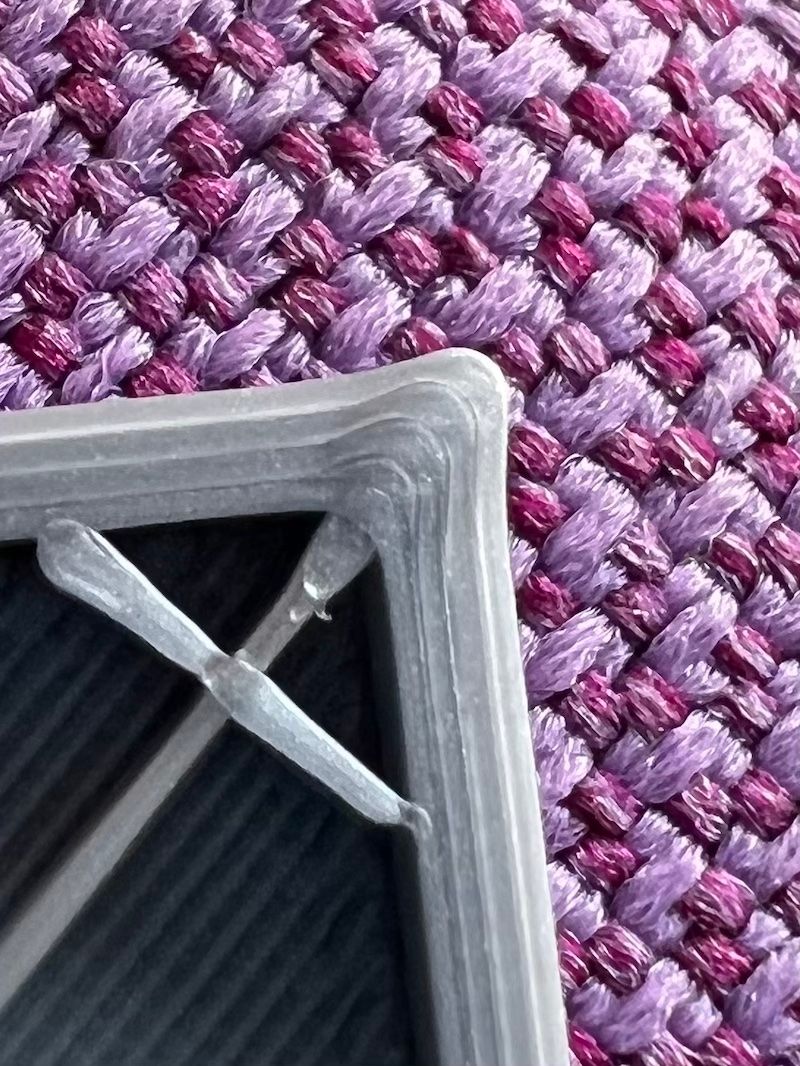
@argo Do you have a picture of that cube showing a corner that is not at the start/end of the inner perimeter? Would be interesting to see what that looks like.
-
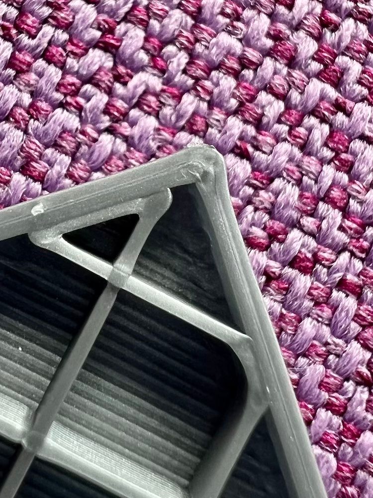
On the following picture you see a corner without retraction. This was also a very slow test at 40 mm/s to rule out overshooting corners caused by too high speed.