not able to get a good first layer using 3PL and bed mesh
-
@moth4017
if i do a height check G30 s-1
results
12/11/2022, 11:04:22 AM Stopped at height 9.786 mm
Cen
ProbeDropOff
12/11/2022, 11:04:19 AM Stopped at height 10.011 mm
RL
12/11/2022, 11:04:15 AM Stopped at height 9.952 mm
RR
12/11/2022, 11:04:11 AM Stopped at height 9.898 mm
FR
12/11/2022, 11:04:08 AM Stopped at height 9.877 mm
FL

looking at the height map the rear left (RL)corner is highest, if i look at the probe height for RL 10.011 is that the correct?
-
@moth4017 if i measure the thickness of the first layer at each corner ,
layer height requested 0.3mm, nozzel dia 0.8mm
FL 0.35
FR 0.19
RR 0.33
RL 0.44 -
@moth4017
You've presented 3 or 4 heightmaps now and they are all different, why?
I guess it's a mechanical issue or you readjusted the frame?Anyway, 0.3 layer with a 0.8 nozzle should stick without mesh levelling, if temp parameters are correct. (and printsurface is OK with type of filament)
Did you check bed temp for consistency at all corners? Maybe the bed gets cold air on one side? -
@o_lampe hi , i readjusted the frame , removed the stepper motor extuder etc and just fitted a probe only , got all the tramming done , got a good 3 point leveling and a good flat level bed mesh which was repeatable.
reinstalled the extruder stepper motor re did the 3PL and bed mesh noticed the mesh was flat but tilted , it was the cable loom to the tool head causing the tilt, re did the cable loom.
3PL and mesh again flat and level again, did a print 300 x300 first layer as above but the result was the same right hand side was a good squish but the left hand side was the same as before barly attached to the bed..
i have tried printing on a cold bed too same result
-
@moth4017
Could it be overcompensation?
Did you tune the Z-axis steps/mm?
No one counts teeth of a belted gearbox, right? We just assume, the vendor did...
But sometimes they round up or down... -
@o_lampe i wish it was that easy , i check each z axis with a dial gauge just to make sure they were all moving the correct amount.. but i like your thinking ,
im not sure what else i can do , i even looked if i could manually adjust each motor with a offset just as a test ...
-
@moth4017 said in not able to get a good first layer using 3PL and bed mesh:
i even looked if i could manually adjust each motor with a offset just as a test ...
Been there, done it

IIRC, you could edit the heightmap or put a sheet of paper on the right side while mesh-probing.
But best practice is to find the cause for it. (stiffen up a sagging gantry or placing the filament spool elsewhere had helped me in the past) -
@moth4017 Can you post a picture of your test print on the bed, in particular the lines that run left to right and right to left (make sure we can see both lines clearly).
I've lost track of what it is you are doing now. Are you still using the probe attached to your printhead for the levelling? If so after you have done all the probing it might be worth checking that the nozzle tip is the same height from the bed on each side (at locations that the probe reads the same height). So basically test for any sort of change in probe offset from one side of the bed to the other. It is important to use the actual nozzle for this (with filament loaded) as pull on the nozzle may be causing issues.
If your heightmap now looks level it is probably worth doing a print without the heightmap active (use G29 S2) to satisfy yourself that it is not having any impact on things.
-
G28,G32 print first photos are at the mid point of each side 0.8mm nozzle 0.3mm layer height , 3 rounds of 3 point leveling on the g28 ,
on the right hand side of the print the extruder was starting to skip steps.
the order below front, right hand ( was skipping steps), rear, left hand


-
G28, print first photos are at the mid point of each side 0.8mm nozzle 0.3mm layer height , 3 rounds of 3 point leveling on the g28 ,
on the right hand side of the print the extruder was starting to skip steps.
the order below front, right hand ( was skipping steps), rear, left hand
sorry about the quality of photos, the LED lighting in the printer not good..


-
@moth4017 looks like the G28 prints slightly better
-
@moth4017 I really wanted to see an overall picture of the print on the bed to judge how things changed. But if it is not possible to get that a good shot of that never mind. Did you do the test of nozzle height v probe result that I suggested?
-
@gloomyandy I will do the nozzel height check tonight
-
@gloomyandy
bed size 304 x 304
did a 3PL and i watch and recorded the z heights as it triggered
Fl 10.06 x2 y2
FR 10.06 x 304 y 2
RC 10.07 x150 y277 ( its 277 not 304 as that the closest i can get the sensor to it)i then set the nozzel to the same coordinates and measured the distance nozzel to bed with fealer gauges
g1 x2 y2 z0 >0.7 <0.8
g1 x304 y2 z0 <0.0 in to the bed
g1 x150 y277 z0 > 0.1mm <0.15just to check there is no offset with the difference in the 10mm off set im going to set z to 10mm and remeasure
FL 10.06
FR 9.81
RC 10.06 -
i think this has fixed the issue but nut sure why, this is the only file i changed .
before
; homeall.g
echo "Home All.g "

M98 P"/sys/homey.g"  		;P define the parameter and is not part of the name
M98 P"/sys/homex.g"  		;P define the parameter and is not part of the name

M98 P"/macros/ProbePickUp"	; probe pick up

M98 P"/sys/homez.g" 		;P define the parameter and is not part of the name
M98 P"/macros/3PL"			; 3 point leveling;M98 P"/macros/3PL"			 ;3 point leveling

M98 P"/sys/homez.g" 		;P define the parameter and is not part of the name
M98 P"/macros/3PL"			; 3 point leveling;M98 P"/macros/3PL"			 ;3 point leveling

M98 P"/sys/homez.g" 		;P define the parameter and is not part of the name
M98 P"/macros/3PL"			; 3 point leveling;M98 P"/macros/3PL"			 ;3 point leveling

M98 P"/sys/homez.g" 		;P define the parameter and is not part of the name
M98 P"/macros/3PL"			; 3 point leveling;M98 P"/macros/3PL"			; 3 point leveling

M98 P"/sys/homez.g" 		;P define the parameter and is not part of the name
M98 P"/macros/3PL"			; 3 point leveling;M98 P"/macros/3PL"			; 3 point leveling
M98 P"/sys/homez.g" 		;P define the parameter and is not part of the name

M98 P"/macros/ProbeDropOff"	; probe drop off
after, added the M561 and G29 s2, also removed the home z inbetween the 3PL
; homeall.g
echo "Home All.g "
M561						;clear bed transforms
G29 S2						;delete bed mesh
M98 P"/sys/homey.g"  		;P define the parameter and is not part of the name
M98 P"/sys/homex.g"  		;P define the parameter and is not part of the name

M98 P"/macros/ProbePickUp"	; probe pick up

M98 P"/sys/homez.g" 		;P define the parameter and is not part of the name
M98 P"/macros/3PL"			; 3 point leveling;M98 P"/macros/3PL"			; 3 point leveling

;M98 P"/sys/homez.g" 		;P define the parameter and is not part of the name
M98 P"/macros/3PL"			; 3 point leveling;M98 P"/macros/3PL"			; 3 point leveling

;M98 P"/sys/homez.g" 		;P define the parameter and is not part of the name
M98 P"/macros/3PL"			; 3 point leveling;M98 P"/macros/3PL"			; 3 point leveling

;M98 P"/sys/homez.g" 		;P define the parameter and is not part of the name
;M98 P"/macros/3PL"			; 3 point leveling;M98 P"/macros/3PL"			; 3 point leveling

;M98 P"/sys/homez.g" 		;P define the parameter and is not part of the name
M98 P"/macros/3PL"			; 3 point leveling;M98 P"/macros/3PL"			; 3 point leveling
M98 P"/sys/homez.g" 		;P define the parameter and is not part of the name

M98 P"/macros/ProbeDropOff"	; probe drop offcode_text
so after some test prints at 300 mm x 300mm its is much better i can still detect a difference of 0.18mm after the 3 point leveling.
doing a g29 mesh does not improve the first layer at all

-
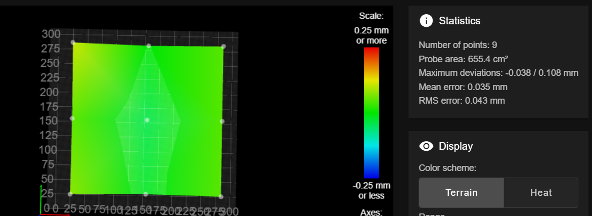
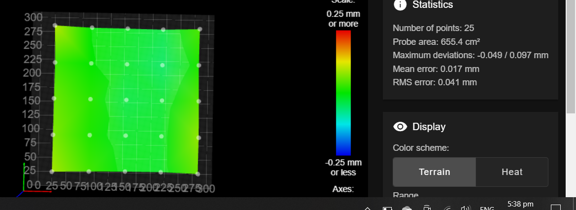
It would help visualize the mesh accurately I think if you used a mesh with a 3x3 grid and used the center point for the same point you set Z0 with a G30. You'll get a truer sense of the actual bed.
-
@Phaedrux 9 point

-
@Phaedrux 25 point

-
@moth4017 said in not able to get a good first layer using 3PL and bed mesh:
i can still detect a difference of 0.18mm after the 3 point leveling.
Have you set your leadscrew positions correct? If no leadscrews, then use the pivot points of the bed instead. All the 3PL probing can only work with correct pivot point coordinates
-
@o_lampe ball joints
M671 X-10:320:155 Y-10:-10:320 S35G30 P0 X27 Y27 Z-99999 ; probe near a leadscrew
G30 P1 X283 Y27 Z-99999 ; probe near a leadscrew
G30 P2 X155 Y283 Z-99999 S3 ; probe near a leadscrew and calibrate 3 motors;Mesh
M557 X27:283 Y27:283 S256