Duet3D Logo Duet3D
    • Tags
    • Documentation
    • Order
    • Register
    • Login

    My Pi Zero 2W Adapter for Duet 3 | Duet 3 Mini 5+

    Scheduled Pinned Locked Moved
    General Discussion
    6
    10
    664
    Loading More Posts
    • Oldest to Newest
    • Newest to Oldest
    • Most Votes
    Reply
    • Reply as topic
    Log in to reply
    This topic has been deleted. Only users with topic management privileges can see it.
    • PCRundefined
      PCR
      last edited by

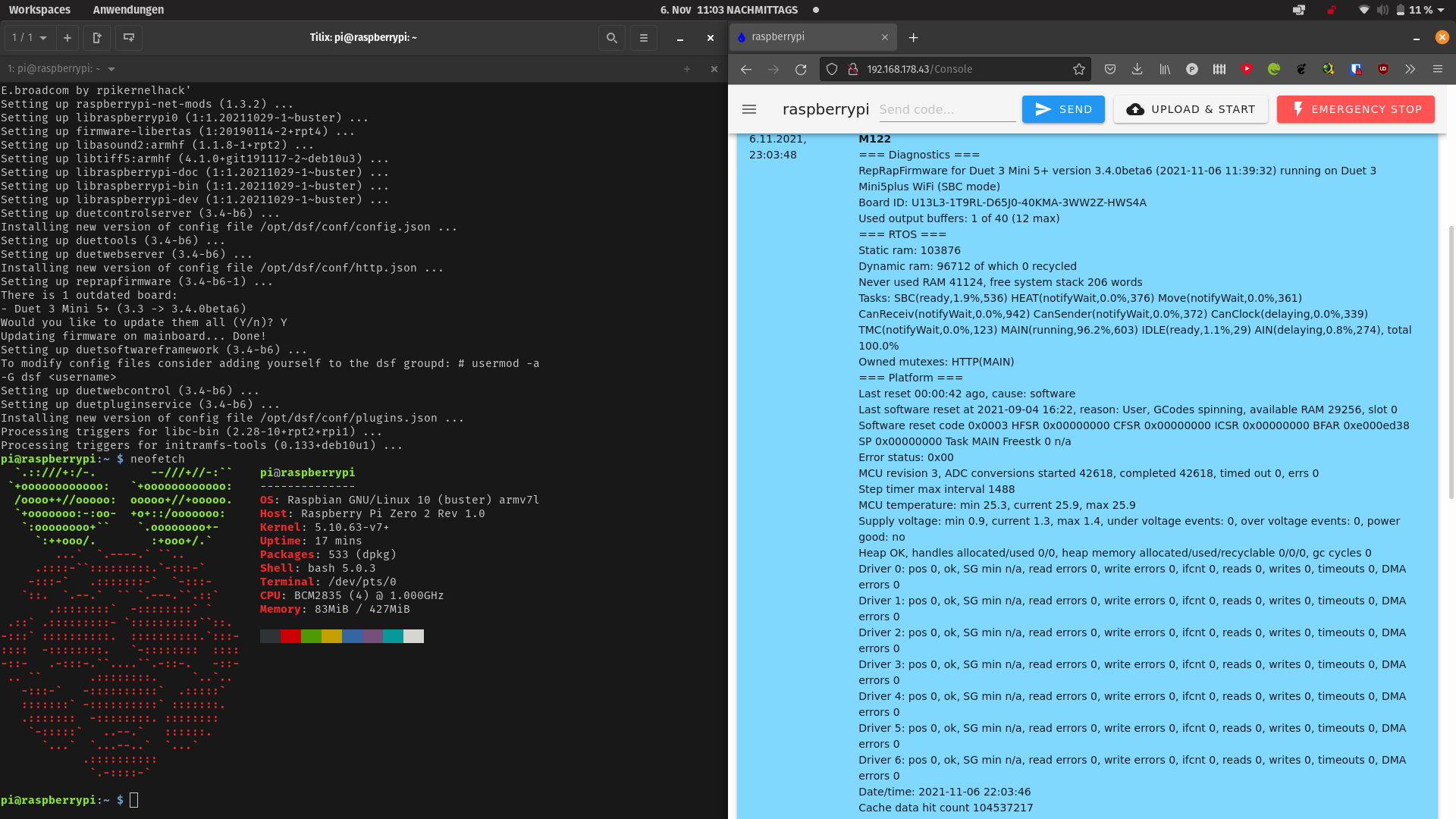
      Tested the PCB today. Works great.

      Have 2 more of the Prototypen!
      Will give it away for shipping. You only need the Pi. I will include connectors

      Best

      And yes i knew the CSI connector... Next Revision will fix it.

      IMG_20211106_230236.jpg

      PCRundefined o_lampeundefined Rushmere3Dundefined Nurgelrotundefined 4 Replies Last reply Reply Quote 4
      • PCRundefined
        PCR @PCR
        last edited by

        @pcr Bildschirmfoto von 2021-11-06 23-03-58.png

        1 Reply Last reply Reply Quote 3
        • o_lampeundefined
          o_lampe @PCR
          last edited by

          @pcr Is there enough clearance for a mini-HDMI_to_HDMI adapter, when the Duet3 header is soldered? The adapter I have is pretty big...

          PCRundefined 1 Reply Last reply Reply Quote 0
          • PCRundefined
            PCR @o_lampe
            last edited by

            @o_lampe If you using a header.for mounting the Pi then yes. I solderd Mine directly on it

            1 Reply Last reply Reply Quote 0
            • Rushmere3Dundefined
              Rushmere3D @PCR
              last edited by

              @pcr This might be a stupid question but what does the adaptor do? Can't you just attach a duet3 to the zero with a ribbon cable?

              Follow my adventures in 3D Printing, laser cutting and electronics. https://linktr.ee/Rushmere3D

              PCRundefined 1 Reply Last reply Reply Quote 0
              • PCRundefined
                PCR @Rushmere3D
                last edited by

                @rushmere3d you could. But with that the Signal way is shorter. You get a USB A Port. And in the next Revision a Buck comverter

                gloomyandyundefined 1 Reply Last reply Reply Quote 0
                • gloomyandyundefined
                  gloomyandy @PCR
                  last edited by

                  @pcr Can you post a picture showing how it mounts on the board?

                  1 Reply Last reply Reply Quote 0
                  • Nurgelrotundefined
                    Nurgelrot @PCR
                    last edited by

                    @pcr Amazing work. Please be sure to post when/if your have a production version.

                    1 Reply Last reply Reply Quote 0
                    • 0nn0undefined
                      0nn0
                      last edited by

                      So, did this board ever make it to production? (or is there a schematic which I could use to have it made at a PCB proto fab?)

                      PCRundefined 1 Reply Last reply Reply Quote 0
                      • PCRundefined
                        PCR @0nn0
                        last edited by

                        @0nn0 sent PM

                        1 Reply Last reply Reply Quote 0
                        • First post
                          Last post
                        Unless otherwise noted, all forum content is licensed under CC-BY-SA