Delta printing height map diagnostics help
-
You guys have been helping me so much, again, I cannot thank you enough! I am back for another question. I have been recently doing bed leveling and find that my height map matches an example in delta calibration that reads, "One of the most common errors would be tower endstop settings. When these are in error, the primary effect is to product a tilt to the bed scan."
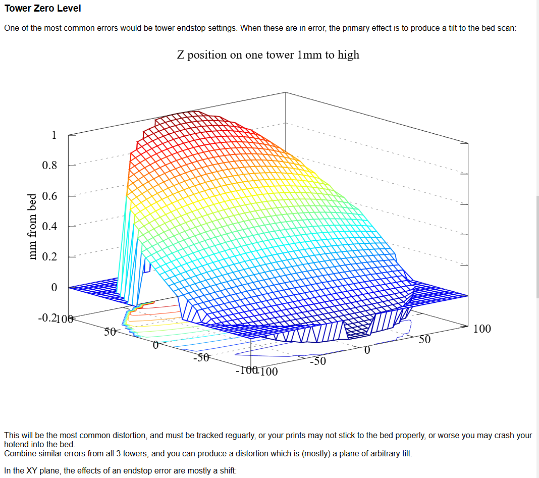
Mine seems to match the description but I cannot for the life of me figure it out.
Below is my config if there's anything else I can show I will gladly!; Configuration file for Duet WiFi (firmware version 2.03) ; executed by the firmware on start-up ; ; generated by RepRapFirmware Configuration Tool v2.0.3 on Thu Sep 05 2019 15:50:44 GMT-0400 (Eastern Daylight Time) ; General preferences G90 ; send absolute coordinates... M83 ; ...but relative extruder moves M550 P"Tall Printer" ; set printer name M665 R180 L160 B130 H580 ; Set delta radius, diagonal rod length, printable radius and homed height M666 X0 Y0 Z0 ; put your endstop adjustments here, or let auto calibration find them ; Network M552 S1 ; enable network M586 P0 S1 ; enable HTTP M586 P1 S0 ; disable FTP M586 P2 S0 ; disable Telnet ; Drives M569 P0 S0 ; physical drive 0 goes backwards M569 P1 S0 ; physical drive 1 goes backwards M569 P2 S0 ; physical drive 2 goes backwards M569 P3 S1 ; physical drive 3 goes forwards M584 X0 Y1 Z2 E3 ; set drive mapping M350 X16 Y16 Z16 E16 I1 ; configure microstepping with interpolation M92 X80.00 Y80.00 Z80.00 E500.00 ; set steps per mm M566 X1200.00 Y1200.00 Z1200.00 E1200.00 ; set maximum instantaneous speed changes (mm/min) M203 X18000.00 Y18000.00 Z18000.00 E1200.00 ; set maximum speeds (mm/min) M201 X1000.00 Y1000.00 Z1000.00 E1000.00 ; set accelerations (mm/s^2) M906 X1100 Y1100 Z1100 E900 I60 ; set motor currents (mA) and motor idle factor in per cent M84 S30 ; Set idle timeout ; Axis Limits M208 Z0 S1 ; set minimum Z ; Endstops M574 X2 S1 P"!xstop" ; X active low and disabled endstop M574 Y2 S1 P"!ystop" ; Y active low and disabled endstop M574 Z2 S1 P"!zstop" ; Z active low and disabled endstop ; Z-Probe M558 P8 C"zprobe.in+zprobe.mod" R0.4 H10 F1200 T6000 ; set Z probe type to effector and the dive height + speeds G31 P100 X0 Y0 Z-.22 ; set Z probe trigger value, offset and trigger height M557 R85 S20 ; define mesh grid ; Temperature Sensors M308 S0 P"bed_temp" Y"thermistor" T100000 B3950 ; define bed temperature sensor M308 S1 P"e0_temp" Y"thermistor" T100000 B4725 C7.06e-8 ; define E0 temperature sensor ; Heaters M950 H0 C"bed_heat" T0 ; heater 0 uses the bedheat pin, sensor 0 M950 H1 C"e0_heat" T1 ; heater 1 uses the e0_heat pin and sensor 1 M307 H0 B0 S1.00 M140 H0 ; Fans M950 F1 C"fan1" Q500 M106 P1 S1 H1 T45 M950 F0 C"fan0" Q500 ; Part Cooling fan M106 C"PartFan" P0 S0 H-1 B1 M307 H0 ; report the process parameters for heater 0 M307 H0 R2.186 K0.17:0.11 D5.67 S1.00 V24.0 ; set the process parameters for heater 0 ; Tools M563 P0 H1 F0 D0 T0 ; define tool 0 G10 P0 X0 Y0 Z0 ; set tool 0 axis offsets G10 P0 R0 S0 ; set initial tool 0 active and standby temperatures to 0C ; Custom settings are not defined M501 ; recall last used parameters -
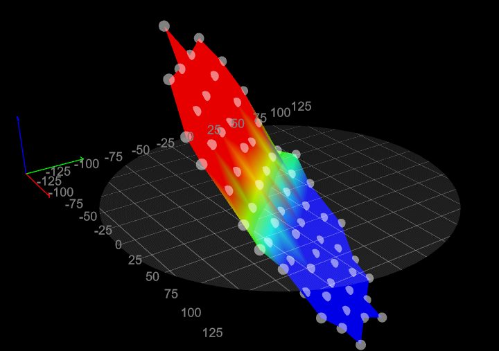
More clarification: I have ran automatic calibration using my duet3d smart effector on a duet3d wifi 2 controller. This is the height map that is generated after running mesh compensation.
-
@sneakyferret posting your bed.g will help people determine how many "types" of calibration you are doing.
This will help understand if you are doing home-switch-height calibration or not.
The bed.g file defines the points that will be probed, and the number of factors that will be calibrated. RepRapFirmware supports the following calibration schemes: 3-factor: Adjusts the endstop switch position corrections (M666 XYZ parameters). 4-factor: Similar to traditional manual delta calibration, but much faster. Adjusts the endstop switch position corrections (M666 XYZ parameters) and the delta radius (M665 R parameter). 6-factor: as 4-factor but also adjusts the X and Y tower position corrections. 7-factor: as 6-factor but also adjusts the diagonal rod length (M665 L parameter). 8-factor: as 6-factor but also adjusts the X and Y tilt angles (M666 A and B parameters). 9-factor: as 8-factor but also adjusts the diagonal rod length (M665 L parameter). -
@alankilian Here it is!
; bed.g ; called to perform automatic delta calibration via G32 ; ; generated by RepRapFirmware Configuration Tool v2.1.8 on Sun Feb 02 2020 21:40:17 GMT-0500 (Eastern Standard Time) ; 13 points, 7 factors, probing radius: 138, probe offset (0, 0) M561 ; clear any bed transform G28 G30 P0 X0.00 Y130.00 Z-99999 H-1.06 G30 P1 X83.56 Y99.59 Z-99999 H-1.25 G30 P2 X128.03 Y22.57 Z-99999 H-1.34 G30 P3 X112.58 Y-65.00 Z-99999 H-0.49 G30 P4 X44.46 Y-122.16 Z-99999 H0.59 G30 P5 X-44.46 Y-122.16 Z-99999 H1.47 G30 P6 X-112.58 Y-65.00 Z-99999 H2.07 G30 P7 X-128.03 Y22.57 Z-99999 H1.28 G30 P8 X-83.56 Y99.59 Z-99999 H-0.08 G30 P9 X0.00 Y65.00 Z-99999 H-0.66 G30 P10 X56.29 Y-32.50 Z-99999 H-0.22 G30 P11 X-56.29 Y-32.50 Z-99999 H0.95 G30 P12 X0 Y0 Z-99999 S6 M500 ; I believe this saves the mesh to EPROM -
I am hoping its just something simple I am missing. You guys are great for everything!
-
I'd give it a good mechanical check over. See if anything is cracked, or loose, or wiggles.
-
@Phaedrux Have been going over it with a fine tooth comb and so far nothing stands out.
-
@sneakyferret I've checked everything mechanical from tower bolts to stepper motor set screws on my delta printer. The only thing I really notice that's suspicious is that my belt tensions may could be tightened further but its not like they're floppy loose.
Anything else come to mind?
-
Generate a new bed.g file? I'm not a delta user, so my help is pretty limited.
When in doubt though it's good to go back to basics
https://docs.duet3d.com/en/User_manual/Machine_configuration/Configuration_linear_delta
https://docs.duet3d.com/en/User_manual/Tuning/Delta_calibration -
@Phaedrux Appreciate the reply, but I have been over the initial calibration and mesh compensations step by step repeatedly, making sure to follow each step and the result is the same.

-
@sneakyferret Ok, update! I was following this instructional here and placed trigger height corrections at each of my bed.g points.
After this, this resulted in the above SUPER skewed height map. I got curious and removed those Hxxx corrections at the end of my bed.g points. Lo and behold:
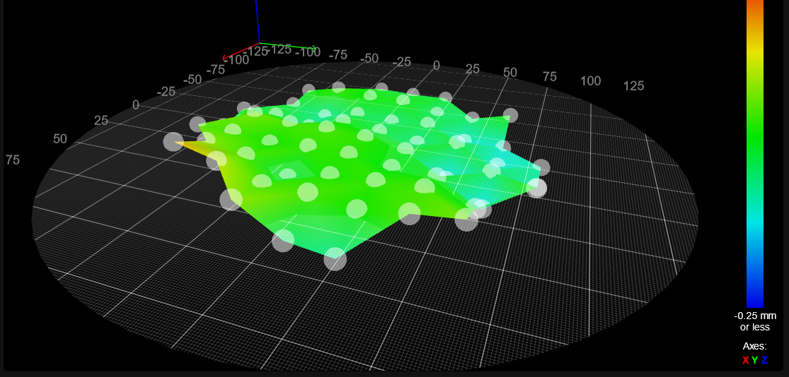
A much more reasonable looking height map!I followed the instructional by measuring trigger height at each of the coordinates and taking that value, subtracting it from the center point trigger height, and placed those values in bed.g. Only problem is I didn't see that it says to place them in G31 commands.. My bed file doesn't contain any G31 commands!

I appreciate no one being impatient with me during this. What exactly is G31 used for? I don't understand what everyone says about it.
-
G31 defines the offset between the nozzle and probe.
https://docs.duet3d.com/en/User_manual/Reference/Gcodes#g31-set-or-report-current-probe-status
-
@sneakyferret you should not need to use trigger height corrections when using a Smart Effector. The trigger height should be much the same all over the bed, typically about -0.1mm. What range of trigger heights did you measure, and how did you measure them?
When you run auto calibration what results does it report?
Duet WiFi hardware designer and firmware engineer
Please do not ask me for Duet support via PM or email, use the forum
http://www.escher3d.com, https://miscsolutions.wordpress.com -
@dc42 not too bad. Max deviations are -.148 and .154 at the low and high end. I measured the trigger heights by taking my bed.g coordinates, driving the nozzle to each point, use G30 S-1 to do a single probe and have it display the trigger height. I'll have to re run auto cal to see what it reads out but my bed leveling looks much better now.