Differential drive with belts (or balls or gears...)
-
@deckingman What a sophisticated system!
I only have to change the steps/degree of one of the steppers to set the gear ratio.
Almost too easy. I wonder, what disadvantages it will show. (torquewise or such) -
@o_lampe Yes it was rather unique. At the time, it was aimed at trucks and other large commercial vehicles because it was too big and heavy to be viable for passenger cars. I didn't have any direct involvement with it - I just helped to commission their exhaust emission facility. The theory was that by varying the final drive ratio ratio, one could maintained the engine speed and load at conditions ideally suited to low emissions. I've no idea how successful they were in achieving that aim though........
-
My bicycle has an Enviolo CVT built into the rear wheel hub. It is a traction drive like those linked above. Efficiency is great when input and output speeds are equal, but drops at as you move toward either extreme of drive ratio. I would expect the same from the toroid drives that operate the same way.
It's fine on my commuter bike, and gets used in a lot of ebikes (the high instantaneous torque of electric motors can snap gear teeth in internally geared hubs), but you won't find them in racing bikes because of the efficiency issues.
-
@o_lampe I'm going somewhat off topic from your original question, but thought I'd chime in with some info.
An IVT is just a modified version of a CVT such that you can change the direction of the output without changing the direction of the input. Typically this involves matching some CVT system with a planetary gearset where all three elements can rotate (sun, carrier and annulus).
There are different ways ways to acheive a CVT but fundamentally, you are looking for some way to change the ratio. With belts, you'll probably have to do this by changing the diameter of the pulley's in some fashion (either a coned pulley pair, or some other weird arrangement I can't visualise). If you do go for the coned menthod, remember that you will always need an axial load to clamp the cones together, else the belt will slip. Belt CVT's have been put into production in a few production cars, but they never really caught on. It's really weird accelerating while the engine sound stays constant (I've driven in one!), plus the efficiency gains on the engine are largely offset by the increased transmission losses and upfront cost - a modern torque converter auto wins out.
Back to printers... to do something like a differential screw drive, you are basically going to have to either rotate the mount of one motor using the other, or do it with differential linear movement, but I think here you aren't really making a CVT - you're just summing the speeds/position, not actually varying the ratio. Is the end goal just to get a high overall ratio?
... and back off topic again... Re the torrotrack unit, the big issues with this are cost and efficiency. They aren't simple units so they end up quite large and expensive. The rolling of the variators has a slight twisting/skidding/spinning at the contact points causing friction losses, but you can't use low friction coatings as it is the friction that is also transmitting the torque. You also have to apply a constant force to clamp the sides together to transmit torque, so you have to have some additional ancillary drive using more energy. More clamping force means more torque capacity, but also more friction and very high contact loads on the variators. I think the biggest issue in automotive applications though is the commercial side - it is a large and expensive unit that needs to be integrated into the rest of a transmission system. If you're a gearbox company, it's not a great business case to sell $10k gearboxes when $8k is going straight through to another company, and the cost to develop your own version would be astronomical. They had some more success in ancillary systems (variable turbos/superchargers etc), but I think are no longer operating as a business.
CVT's in e-Bikes (and some hybrid cars like the Toyota Pruis) tend to use a planetary gearset with a pair of motor/generators linking two of the elements. Essentially this becomes an electrical variator, but as @mrehorstdmd mentions, in the extreme operating conditions you end up just circulating power around the system, meaning high losses.
Source - I work in transmission design so have spent a lot of time looking at various whacky (and not so whacky) systems/ideas!
-
@engikeneer Wow to all of you!
So many elaborated infos are humbling me.
Comparing the different CVT version, my system work more like the one in a Prius but without the planetary gears.I simply sum up two motions and the result varies with their relative speed. I have no specific idea where to put it in good use.
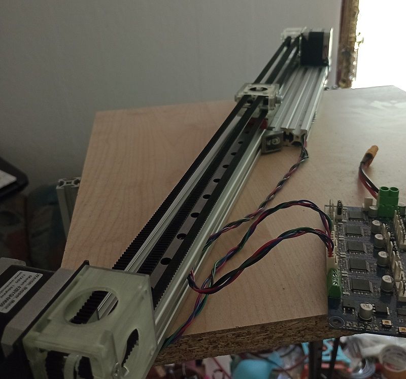
Since it uses two steppers, I can imagine to let them run at their best speed/torque which is at around 50% of max speed.
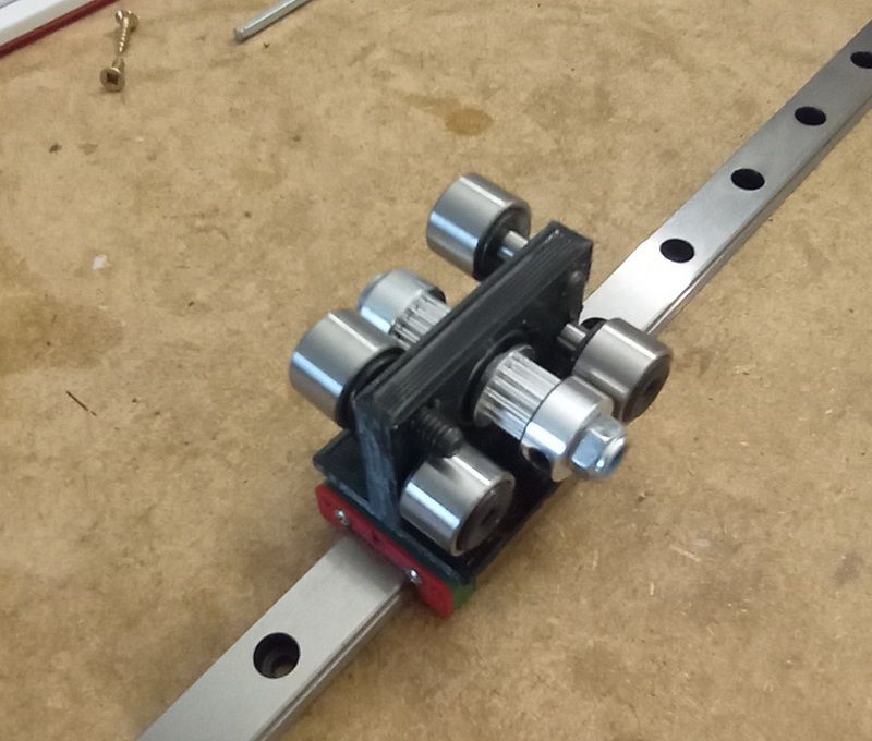
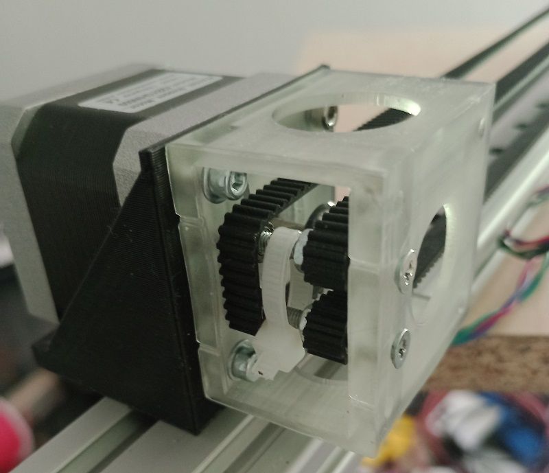
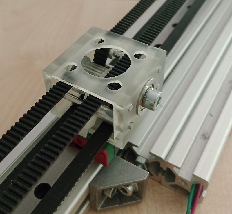
Summing up would then double the output speed without risking losing steps.Here's a first prototype of the carrier
-
I redesigned the belt-system to have parallel and scratch-free belt path's.
It's a tight fit and I have to use very tiny idlers.
But as a proof of concept, it'll do.
I config'd both motors as extruders and used different mixing ratios to test various gear ratios.
The formula to get a 1:25 ratio isE0.52:0.48, which is a mystery to me.
At a mixing ratio ofE0.5:0.5both motors run, but the carrier doesn't move. (infinite gear ratio)
Does anyone have a theoryHere are some pics, how I had to double-wrap the belts to have sufficient contact with the pulleys.
-
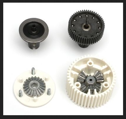
I've changed the title, because there is a simple way of building a differential drive that translates rotary motion into rotary motion (instead of linear)
There are some examples from rc-car tuners that would fit our needs, if we'd drive them 'backwards'.
Some even come with belt pulley on the input (which would be our output). They should be backlash-free but not slip-free (when overloaded)
IMHO, their smooth ballbearing-like motion make them ideal for 5-bar SCARA and robotics.Also there are the classic beveled gear differentials that'll work similar but have opposite characteristics regarding backlash and slip.
-
@o_lampe said in Differential drive with belts (or balls or gears...):
The formula to get a 1:25 ratio is E0.52:0.48, which is a mystery to me.
At a mixing ratio of E0.5:0.5 both motors run, but the carrier doesn't move. (infinite gear ratio)
Does anyone have a theoryThe math behind this is still unsolved.
It already started with a surprise: I'm using 16 tooth GT2 pulleys all over and 1.8° steppers with 16x microstepping, so I expected 100steps/mm when the mixing ratio is E1.0:0 (second belt acts like rack & pinion)
But I had to use 200steps/mm...
The mixing ratio of
E0.52:0.48leads to 104 and 96 steps/mm for a gear ratio of 1:25.
The sum of the mixing ratio has to be 1.0. I tested other ratios and they ended with belts jumping over pulleys.I want to develop a formula to calculate the mixing ratio (or steps/mm) from a target gear ratio.
I noticed that the mixing ratio above is 4% off and100(%) /4 = 25.
The formula for e.g. 1:50 would then be100/50= 2% => 200+1% and 200-1%
If I'd use ratio as a global variable for the ratio, I could use this formula in config.g:~~M92 E{200+100/(global.ratio*2) : 200-100/(global.ratio*2)}~~I think I solved the problem, just by trying to describe it
The example above works for 1:50, but not for 1:1... where's is my mistake?But I'm still puzzled why I have to use 200steps/mm as a starting point....
Any hints are welcome -
@o_lampe said in Differential drive with belts (or balls or gears...):
e example above works for 1:50, but not for 1:1... where's is my mistake?
I think the calculation is:
100 mm move, one moves eg 52 mm, the other 48 mm => (52-48)/100 = 1:25To get 1:1, you would need 100/100=1:1. This would be one moves 100 mm, the other 0, so (100-0)/100 = 1:1. IOW only one stepper moving.
This gear could be interesting for Z move. => coarse positioning and then by changing the ratio fine tuning the Z position.
-
@o_lampe your 200 steps/mm is probably because of it is like a pulley / hoist / winch with 1:2 ratio. (I am not sure, just an idea). Like a "straight CoreXY", each stepper providing part of the movement.
-
@JoergS5 said in Differential drive with belts (or balls or gears...):
@o_lampe said in Differential drive with belts (or balls or gears...):
e example above works for 1:50, but not for 1:1... where's is my mistake?
I think the calculation is:
100 mm move, one moves eg 52 mm, the other 48 mm => (52-48)/100 = 1:25To get 1:1, you would need 100/100=1:1. This would be one moves 100 mm, the other 0, so (100-0)/100 = 1:1. IOW only one stepper moving.
This gear could be interesting for Z move.
This formula explains it much better, but I've stared too long on my own wrong formula. I need a second coffee to build a reverse formula from it.
re: Z move
It depends on the output torque. If you are right about the 'winch' theory, we produce only double the torque, no matter what the gear ratio is.
Many people use 3 or 4 motors for Z-axis. Hard to imagine someone would use 6 or 8 motors just for Z. -
@o_lampe said in Differential drive with belts (or balls or gears...):
double the torque,
my argument was more the idea to get high precision.
Your goal seems to be more torque. I bought some gears to build something and then was disappointed that the maximum torque was limited. In my understanding the torque is only one aspect, the maximum load-bearing capacity is an important aspect also. So you may achieve 1:100 ratio with a very high torque, but breaking your parts.
-
@o_lampe said in Differential drive with belts (or balls or gears...):
formula
There is one more idea I had. When reading about harmonic drive, I read the post of https://www.cnczone.com/forums/linear-and-rotary-motion/261174-cnc-engineering-3.html and on page 3 of 3-14-2015 was the comment that it depends on which parts are moved and which ones are fixed. The ratio will differ between R:1 and R+1:1, so you may experience a crude ratio in your experiments. (in the lower half of this post)
-
@JoergS5 I replied to you before you edited the post.
This extra fine movement I can achieve, could be helpful for Astro-photography, but I'm sure those geeks have already found out a similar way to follow Venus")
-
@o_lampe said in Differential drive with belts (or balls or gears...):
Astro-photography
yes, those astro people have impressive web pages and projects!
-
I figured out how to universally calculate the M92 values for motor 'a' and motor 'b':
Based on 200 steps/mm and gear ratio expressed as e.g. "20" for a 1:20 ratioset global.ratio = 20
motor 'a' = M92 a{ 200* (0.5 + 0.5/global.ratio) }
motor 'b' = M92 b{ 200* (0.5 - 0.5/global.ratio) }Now I can start using the mixing ratio for real axes by modifying the kinematic matrix.
For a cartesian X-axis it should be:
M669 K0 X0:0:0:0:0:0:1:1 // using a and b axesI will test it today fingers crossed
//edit
Defining variables has changed?var ratio = 20 M92 U{ 200* (0.5 + 0.5/var.ratio) } M92 V{ 200* (0.5 - 0.5/var.ratio) }works
Also the matrix "requires" the original axis to be present, although I can set M92 X0 and it works as expected
")
M669 K0 X1:0:0:1:1 // using U and V axes -
@o_lampe
With the formulas above I can scale down a motion system without loosing precision, but RRF doesn't know it is printing smaller.To move the tool in 1:1 scale but with increased precision I have to multipy the steps/mm with the gear ratio:
var ratio = 20
M92 U{ var.ratio * 200 * (0.5 + 0.5/var.ratio) }
M92 V{ var.ratio * 200 * (0.5 - 0.5/var.ratio) }
Furthermore I have to consider the impact it has on max. speed, accel and jerk. The rotor inertia of two fast spinning motors play a much bigger part compared to the mass of the toolhead.
A simple way to deal with it will be to divide e.g.max. speed / ratiobut that isn't spot on.
I'd like to hear your opinions about it. -
@o_lampe This may, or my not be relevant but my new machine has "remote" motors. That is to say, the pulley that drives the belts is fixed to an 8mm diameter shaft with consequently much bigger bearings than those found inside Nema17 stepper motors. A second pulley connects the motor to that shaft. This also gives me the opportunity to use asymmetrical pulley sizes and I thought that I could use a 20 tooth pulley on the motor, and a 40 tooth pulley on the shaft. As well as doubling the steps per mm for greater precision, this would also effectively double the torque applied to the gantry. Which is true at low speeds but at faster speeds for non-print moves, the motor torque starts to drop so the effective increase due to gearing was partly negated. But the real killer was back EMF due to rotation. When I plugged the numbers into the calculator, the maximum speed I could use was 200mm/sec and I like to use 350 for travel moves. Noise was also an issue - it was noticeably louder and harsher with the motors running twice as fast. So I've reverted to 20 tooth pulleys on both the motor and the drive shaft giving me 1:1 gearing.
-
@deckingman Thanks for the reply, it is relevant to compare pro's and con's of fixed gear motion and the flex. gear ratio I can achieve.
As @JoergS5 already mentioned, he saw an advantage for z-motion, where I can set ratio to 1:1 for coarse homing and for fine homing and probing, switch to a higher resolution.
Same would partly apply in your usecase (if you could detect travel moves vs. print moves) : do travel moves with 1:1 ratio and switch to 1:n ratio for printing.
Only downside is, that the output torque doesn't relate to the gear ratio. I haven't done any weight lifting but I'd be surprised if the output torque would be greater then 2* motor torque. -
@deckingman said in Differential drive with belts (or balls or gears...):
the real killer was back EMF due to rotation.
I've noticed that I can use higher gear ratios than 1:1. With a ratio of 2:1 I could double the output speed without changing the back EMF or loosing steps due to torque degradation.
In fact, most CVT drives are used to maximize efficiency by using the motor at it's best RPM.
In our case the sweet spot is slightly above 50% of max. RPM. That's where torque degradation starts to kick in.