Hollow shaft extruder
-
@JoergS5 Good find! The actual weight is nowhere stated, but they mention package weight of 67grams..
Drilling through the shaft is mentioned a few times in the Schnekenstruder thread. Usually the shaft already has a center-drill and they are not hardened. -
@o_lampe I see no problem to bore the shaft, but disassembled from the stepper and using a lathe, boring half way from both sides. Rotating the shaft and using the drill non-rotating. With good cooling.
I have a lathe, I could try it for you, but I need multiple shafts because the first tries will probably fail *). 8mm would be much easier than 5 mm.
*) thinking about it, this doesn't need to be a stepper shaft. I have enough steel shafts...
Another idea, buy a normal nema 17 with hollow shaft and exchange the shafts
with a light stepper. -
@JoergS5 Another idea - clamp the motor in a drill dress press then rotate the shaft by driving the motor against a non-rotating drill bit
") (That wasn't really a serious idea but it would save disassembling the motor ..........).
(That wasn't really a serious idea but it would save disassembling the motor ..........). -
Hollow shaft stepper motors are commonly used in open source pick-and-place machines, with the suction to pick up the part fed through the shaft. You may be able to find out more about hollow shaft motors by asking at https://groups.google.com/g/openpnp.
-
@deckingman Let's see if a rotary axis limited to 2^31 angle degrees will be enough to drill through 13mm steel
")
-
@JoergS5 Don't waste your time with these experiments.
I disassembled a N17 pancake and the shaft is only pressfit into the rotor. Easy job to drill it hollow with a lathe. The hole doesn't have to be super centric. 2.5mm will do for sure. -
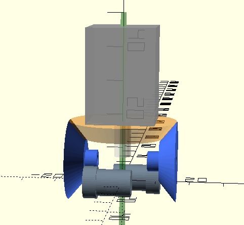
I played around with the beveled gear design and tried to figure out what gear ratio I could achieve.
The BMG dual drive gears are a real spoilsport, because the distance between the hobbed gear and the spur gear doubles up when mounted as shown.
The blue bevel gears can't be much larger, and the 2nd stage straight gear much smaller.
The estimated teethcount now is:
orange gear 64T
blue bevel 48T
blue spur 12T
BMG spur 17TThat sums up to a gear ratio of 1:4, that's less than any other geared extruder has.
 (unless I miscalculated, which is possible)
Q: why is the gap between hobbed and spur gear so big? Isn't there a better way to make them?
-
@o_lampe I was thinking more along the lines of the image below, using a hypoid gear.
The gear ratio is about 2:1. There's just about enough space between the larger gear and the driven hobbed insert (about 4mm) for the second hobbed insert to be in a lever housing, like in most other extruders. But you could increase the size of the gear on the motor shaft, and reduce the size of the large gear, all the way down to 1:1 (assuming the motor is strong enough for direct drive) if you needed more space. Or increase the distance between the motor and the hobbed inserts for a higher gear ratio and smaller, lighter motor.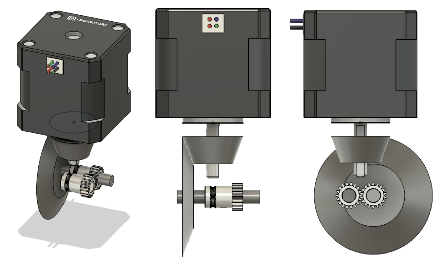
Ian
Bed-slinger - Mini5+ WiFi/1LC | RRP Fisher v1 - D2 WiFi | Polargraph - D2 WiFi | TronXY X5S - 6HC/Roto | CNC router - 6HC | Tractus3D T1250 - D2 Eth
-
Turns out my idea is pretty much the same as this one that @T3P3Tony posted about in the other thread, which looks pretty neat: https://youtu.be/eI0tD69wD18
That one uses a NEMA14. I saw pictures of it and assumed it was a NEMA17, so perhaps wouldn't be too top heavy.I think it would be worth contacting Jason at LDO to see if they have/can make any lighter pancake or round stepper motors with hollow shafts, for either the hypoid version or the Archimedes screw version.
I'd say the Archimedes screw version wins on compactness, at the expense of some concerns about the filament spinning and extrusion inconsistency, though these might be avoided with more refinement of the design and manufacturing process. Alternatively, fitting something like a filament monitor, but with a shaft encoder on it, and running the extruder in closed loop mode would help.
Ian
Bed-slinger - Mini5+ WiFi/1LC | RRP Fisher v1 - D2 WiFi | Polargraph - D2 WiFi | TronXY X5S - 6HC/Roto | CNC router - 6HC | Tractus3D T1250 - D2 Eth
-
@droftarts I'm not happy with the dual drive gears somewhere in the middle of the assembly. They should be lowest as possible (e.g. for flexible filament)
That's why I didn't increase the blue bevel gears in my sketch.The ingenius extruder is quite impressive, but top heavy IMHO.
A two stage gearing would make it more compact, I guess.
Those square NEMA14 motors are so heavy compared to the round ones, I'm surprised, he picked one of these...The hypoid drive reminded me a bit of a worm drive, which might be an option, too?
Which CAD system can calculate them? (hypoid) -
@o_lampe said in Hollow shaft extruder:
@droftarts I'm not happy with the dual drive gears somewhere in the middle of the assembly. They should be lowest as possible (e.g. for flexible filament). That's why I didn't increase the blue bevel gears in my sketch.
Good point. A smaller second gear would bring it closer, at the expense of gear ratio.
The ingenius extruder is quite impressive, but top heavy IMHO. ... Those square NEMA14 motors are so heavy compared to the round ones, I'm surprised, he picked one of these...
Yes, that was my initial thought, too.
A two stage gearing would make it more compact, I guess.
But more backlash/complexity/cost?
The hypoid drive reminded me a bit of a worm drive, which might be an option, too?
It's kind of a cross between a spiral bevel gear and a worm drive. See https://en.wikipedia.org/wiki/Spiral_bevel_gear#Hypoid_gears
The advantage is that it can transmit more torque than a spiral bevel gear, but, like a worm drive, they also have some sliding action along the teeth.Which CAD system can calculate them? (hypoid)
This is about the only CAD tutorial I could find for making hypoid gears, though uses Blender, I'm sure it could be done in Fusion 360 or OpenSCAD: https://youtu.be/wWn9gYwnONk
There's a calculator here http://www.otvinta.com/hypoid.html (they also have calculators and videos for other gearsAlso, if it helps your design, Orbiter v2.0 uses shorter drive gears; 11mm vs 15mm. You could reduce the size of the motor gear, then.
Ian
-
@droftarts Way ahead of you
-
@nikscha I saw... I give up! Yours is very nice, I like how you're trying to squeeze the filament sensor in there too. How did you model the hypoid gear? I saw from your videos you're using Fusion 360.
Ian
Bed-slinger - Mini5+ WiFi/1LC | RRP Fisher v1 - D2 WiFi | Polargraph - D2 WiFi | TronXY X5S - 6HC/Roto | CNC router - 6HC | Tractus3D T1250 - D2 Eth
-
@o_lampe said in Hollow shaft extruder:
@droftarts I'm not happy with the dual drive gears somewhere in the middle of the assembly. They should be lowest as possible (e.g. for flexible filament)
That's why I didn't increase the blue bevel gears in my sketch.The ingenius extruder is quite impressive, but top heavy IMHO.
A two stage gearing would make it more compact, I guess.
Those square NEMA14 motors are so heavy compared to the round ones, I'm surprised, he picked one of these...The hypoid drive reminded me a bit of a worm drive, which might be an option, too?
Which CAD system can calculate them? (hypoid)*Ingenuity Extruder

I actually ordered a round one from LDO, and torque per weight seemed to be much better for the square one. Obviously this is only in the prototype stage (I am actually looking for beta testers right now), and any help with the motor design would be appreciated!
I used a blender tutorial to model the hypoid bevel gears. Rest is done in fusion. But there are also proper calculators (MIT calculator) for hypoid bevel gears.
-
@droftarts I followed a blender tutorial hahaha. The math is done here for you: http://www.otvinta.com/hypoid.html
I want to open source this design under Creative Commons, so any help is appreciated!
I'm actually looking for beta testers, and maybe we can make this a kit!
-
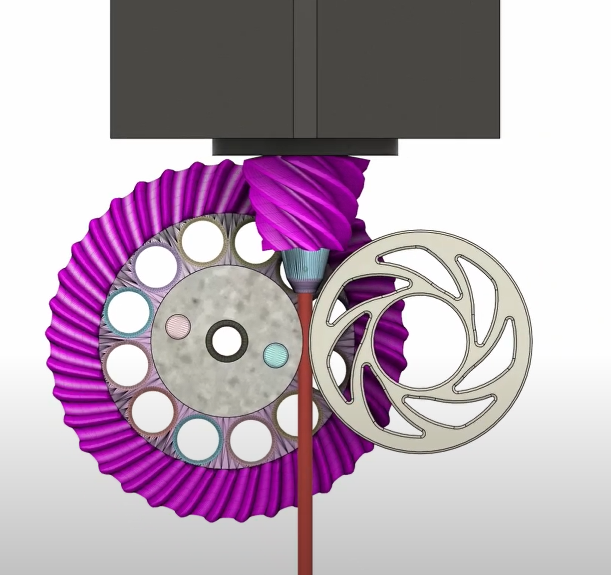
Damn I wanted to wait a bit longer with posting about the Ingenuity extruder on the forum but I guess it's too late now

It's a direct drive extruder which features a hollow-shaft Nema-14 stepper motor, Bondtech LGX drive gear, an eccentric breach which is self-locking, an idler wheel where the spokes act as a tensioning spring and a hypoid bevel gear pair, archiving a gear ratio of 37:7.
The whole mechanism features only 4 moving parts: two gears, the idler wheel and the breach-lever. Weight is 229g.
-
@nikscha Do you think there's any way you can reduce the diameter of the large gear? My first impression was that it would be a bit top heavy, though a lighter motor would help with that. @o_lampe 's point about it being a long way from the drive gear to the hot end, particularly for flexible filaments, could also be problematic.
What is your view on the Archimedes screw extruder?
Ian
Bed-slinger - Mini5+ WiFi/1LC | RRP Fisher v1 - D2 WiFi | Polargraph - D2 WiFi | TronXY X5S - 6HC/Roto | CNC router - 6HC | Tractus3D T1250 - D2 Eth
-
Sorry for highjacking this post by the way, I made a separate one here:
https://forum.duet3d.com/topic/32876/ingenuity-extruder-for-smart-effector -
@nikscha said in Hollow shaft extruder:
Sorry for highjacking this post by the way
No worries, after all your extruder is a hollow shaft extruder, and that's what this thread is about!
Ian
-
@droftarts said in Hollow shaft extruder:
@nikscha Do you think there's any way you can reduce the diameter of the large gear? My first impression was that it would be a bit top heavy, though a lighter motor would help with that. @o_lampe 's point about it being a long way from the drive gear to the hot end, particularly for flexible filaments, could also be problematic.
What is your view on the Archimedes screw extruder?
Ian
Well the diameter of the "wheel" depends on multiple factors, like hypoid offset, gear ratio and number of teeth.
The hypoid offset is limited by the diameter of the drive wheel, which is the bondtech LGX in my case. gear ratio is aimed at 1:7, and tooth size is limited by the material properties.
I made all my prototypes from resin gears (Sirayatech white mecha), which were quite brittle, but I've since moved to gears made from IGUS SLS plastics. They're much stronger and more durable, and with them it might be possible to have a smaller wheel and/or a higher reduction ratio.While testing I found that the "top heaviness" isn't that much of a problem, I'll post my input shaping results later for proof
.
.
.About the Archimedes screw extruder:
Very neat! And so light! I am jealous!
But there's no way of tensioning the filament, and loading/unloading can only be done electronically.
A harder filament will also provide more resistance to deformation which might stall the extruder. A softer filament might slip. There's also only one "teeth" engaging with the filament, so it might slip easier, especially considering that there's no way of tensioning it.
Abrasive filament will also dull the knife edge.Edit:
A quick calculation shows that at 15degree pitch one revolution of the screw will advance the filament by about 1.5mm (tan15 * 1.75 *pi), the archimedes extruder has (360/1.8)= 200 steps per revolution, so about 133.33 steps per mm, which is not that much.Edit2: judging from this: https://youtu.be/YTADdWiFQnI?t=238 my math is wrong, and the archimedes extruder needs about two revolutions to advance the filament by 1.75mm, which implies 1.14 revolutions for 1mm. This is equal to 228 steps/mm
-
 undefined nikscha referenced this topic