Hollow shaft extruder
-
Today I had the first test with the step-dir interface of simpleFOC.
It was a bit of a learning curve to get it working with the magnetic sensor I had.
Running the motor in open loop is no option, the motor gets pretty hot.
In closed loop the motorcurrent is reduced to the actual required torque.
I wanted to give it a real-world extruder-test and ran a typical gcode, but with the XYZ steppers absent, I got tons of errors. (motorphase disconnected)
I wonder how I can get rid of those messages? -
@o_lampe set the motor currents on XYZ to 0, that should stop the errors
-
@o_lampe you could just connect some resistors with the same resistance as a normal stepper motor winding and set the current really low.
I'm guessing that shouldn't break anything and would fool the board into thinking a stepper is connected...Or just connect any random spare motors you may have lying around...
Just a thought...
-
Thanks all for the tips, it's running now.
Just had to add thermistors
It's fun to see the motor almost jump off the table when retracting
-
@o_lampe from another thread, courtesy of @chrishamm
If you set the motor current [...] to less than 500mA, you should not get any "phase disconnected" warnings even if you leave it disconnected.
-
@oliof Thanks, that's what I did.
And adding a thermistor, because I just took the SD-card from my Delta printer and wanted to keep the config.g as original as possible.It will take a while, before I can test the setup on any screw extruder, so I thought of a different way to test the BLDC in a real scenario.
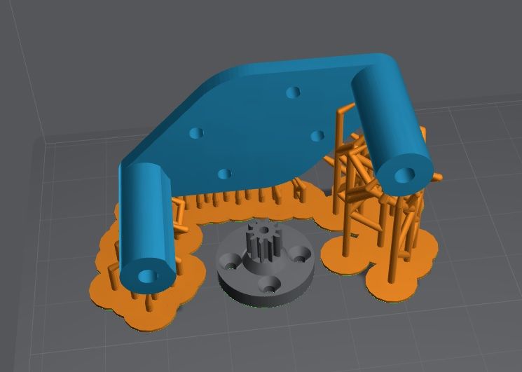
What If I mount it to my sherpa mini instead?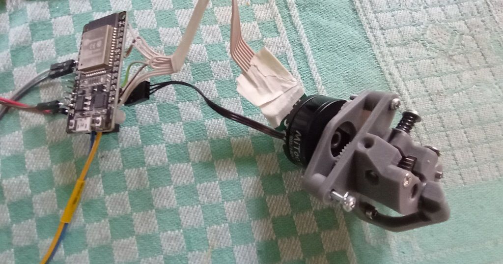
-
Guess, what's printing right now

Wondering how long the gear will last. In my harmonic drive experiments, they lasted a few days with a medium load.
-
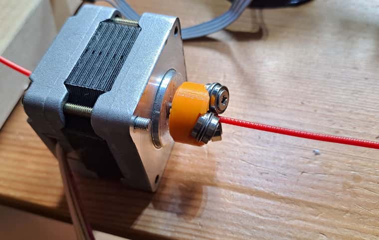
Did a longer torture test with the BLDC-sherpa.
I was able to extrude PLA+ at 210°C with 6mm/s => 14mm^3 .
The resin-spur gear was the limit, but motor and simpleFOC driver were still cold.IIRC, my NEMA14 stepper can only extrude at 3mm/s.
I think, I will mount it permanently on my Delta and make some speed-benchys.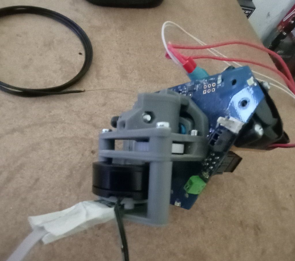
-
First print today

Instead of a benchy, I tried the extruder-woodgrain test. Yes there is some, but hardly visible. The corners were sharp and even, that was a relieve. The close loop PID setting are quite soft, so I expected worse...
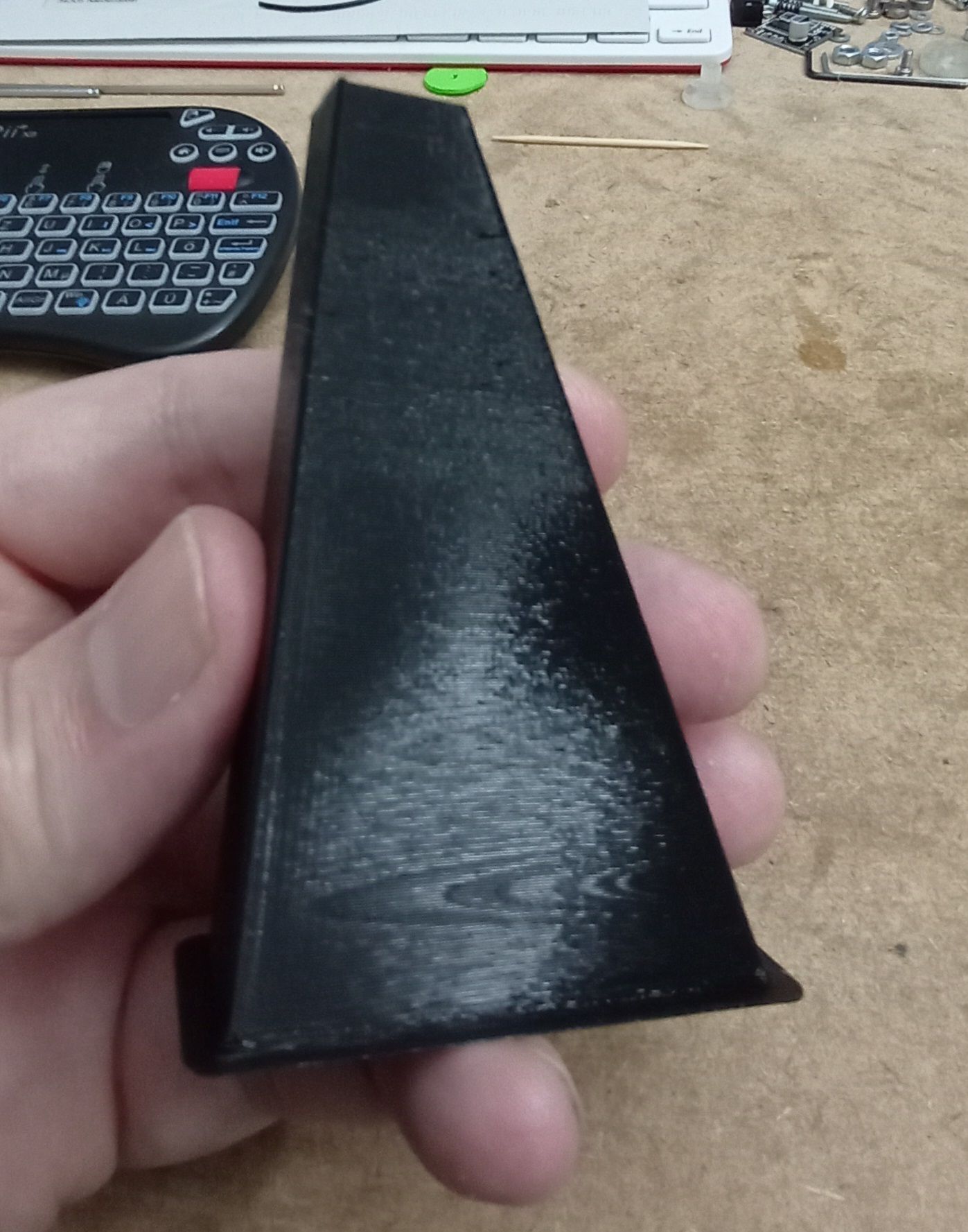
At the top third, the printspeed got so low, that the filament overheated. 10°C less temp and it was nice and shiny again.
-
Speed test : done
I printed a dual color Moai head with 0.25mm layer height and increased speed until it reached 180mm/s (technically, not always real speed)
It wasn't the BLDC extruder that got in trouble. I saw lots of ringing, but upto 150mm/s I saw no signs of under extrusion.
If my math is correct, 0.25mm * 0.4mm *150mm/s = 15 mm^3 volumetric flow?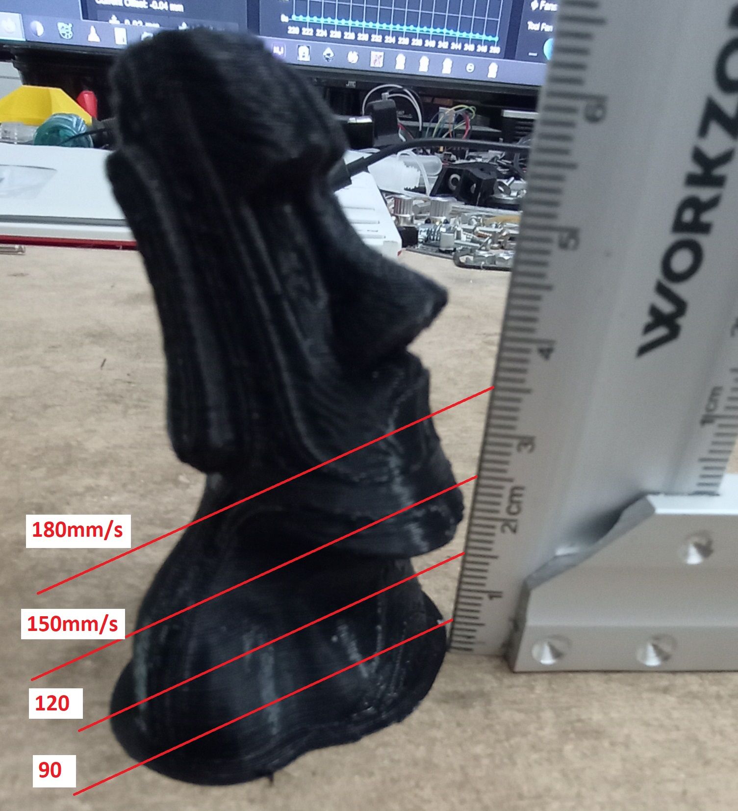
-
Great work. I'm keen to see how this works with VDE when I get the time for it.
Are you not using input shaping for the ringing?
-
@tombrazier Send my some grinded bearings and I can test it
I'd trade it in for a resin-printed carrier...I'm using input shaping, but it was tuned for 80mm/s. Any other speed and it's off.
I was under the impression, that it doesn't work well on deltas anyway? -
@o_lampe Happy to grind and send some bearings. E-mail me at tom at firstsolo dot net.
IS with delta is possible in principle. I understand resonances might vary across the print bed, though. They should not vary with speed. Marlin only has IS on two axes at present (I'd love to have the time to fix this one day!) so deltas are not really supported for IS. I have no idea whether RRF or Klipper have IS for deltas. As I understand it, though, RRF's IS implementation may have issues for any printer. If I have understood correctly then RRF attempts just to do IS on corners which makes a mess with short segments.
-
@tombrazier RRF does support input shaping on deltas but not on other nonlinear kinematics.
Duet WiFi hardware designer and firmware engineer
Please do not ask me for Duet support via PM or email, use the forum
http://www.escher3d.com, https://miscsolutions.wordpress.com -
Thanks @dc42. Am I also right in thinking that RRF's input shaping just targets corners as opposed to summing two or more complete paths made from a time-shifted and scaled original path?
-
@tombrazier RRF input shaping adjusts the acceleration profile to cancel or reduce ringing over a range of frequencies.
Summing two complete paths is similar to ZV input shaping. ZV is poor because it has a V-shaped cancellation curve, meaning it cancels well at just one frequency; so RRF doesn't support it, and neither does Klipper.
-
Success! I've finally completed a 16 minute benchy with my VDE extruder. Somewhat under-extruded in places, but pretty good considering. The rest of the machine hardware is also pretty low spec. 12V bedslinger running on an 8 bit AVR mainboard. Posted a video on youtube.
That's been a long-running project. Glad to put it to bed.
Next up: a new VDE idea to try with 3 pairs of flanged bearings. (And @o_lampe then I'll send three of the bearings to you. It was while I was grinding them that it occurred to me that three extra bearings might be an interesting thing to test!)
-
My latest VDE design is even better than the one I used for the 16 minute benchy. It features two pairs of flanged bearings mounted back to back plus a plain bearing.
I'd like to experiment with three pairs of flanged bearings but need to buy more bearings before I can do that.
Here are some graphs to give an idea of how different designs are affected by compression of the helical thread: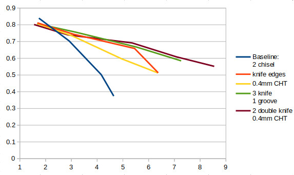
Y is thread pitch / theoretical thread pitch and X is actual linear extrusion speed in mm/s (i.e. taking compression into account).
- The baseline is what I was using when this thread started. It has two chisel edged bearings and a plain bearing and is extruding through a traditional 0.5mm nozzle.
- The red line has larger bearings with knife edges (i.e. a / shape rather than a |/ shape). Both of these reduce compression effects. These are lower quality bearings and I believe this accounts for the red line performing worse at low speeds.
- The yellow line replaces the nozzle with a 0.4mm CHT clone from aliexpress which I have modified to enlarge the three holes so that there is a sharp edge in the middle rather than a flat face. These clone CHT nozzles actually increase back pressure at low flow rates but they do not have the sudden drop off at around 6mm/s.
- The green line is the extruder I used for my 16 minute benchy. It replaces the plain bearing with a knife edge bearing so it has three knife edges rather than 2.
- The last line is my latest experiment with 2 pairs of back to back knife edged bearings. This is slightly better and is the only extruder where I have been able to extrude at an instructed 12mm/s (and getting 8.54mm/s) without the compression causing the knife edges to start falling into the wrong helical thread path, causing inconsistent extrusion.
-
The type of bearings used will wobble a bit on the axles because they have a single set of balls in the race. HDD head armature bearings seem to be built so they can't wobble- either they use needle bearings or they have more than one race and set of balls. They are small, flanged, and often have a threaded stud. They are free if you have a few old HDDs available. They might be ideal for this application:

-
@mrehorstdmd I like the thinking behind it, but these bearings are made for silent and smooth run with a balanced load.
I wonder how long they last when you put them under stress with axial and radial load? And how would we get enough of them to satisfy the expected huge demand?")
@tombrazier
Maybe it's better to pressfit a collar on a normal bearing? It could sit in the center above the balls and we could grind the edge before it is pressed on.
The fit wouldn't need to be tight. A bit of Loctite would fill the smallest gaps and keep the collar in place.The collar could be lasercut from a springsteel sheet with a starfish-like cutout in the center. Then we bend the cutout 90° with a tool in a benchpress.
//edit
even better: press 3 of the starfish legs in one direction and the other three in the opposite direction.