Hollow shaft extruder
-
@o_lampe In a way, the diameter itself is not all that important because you can just print a carrier to match whatever diameters your bearings came out at. e.g. one of the carrier models I sent you has bearing diameters of 9.88mm, 9.6mm and 9.1mm because, after a lot of experimenting, those were the bearings I had to spare. But if you can get them all to the same diameter it does simplify matters.
What does matter is that the edge is symmetrical. Bite depth is quite small. I use 0.1mm. So if the edge on the bearing is slightly ovoid or has flat spots you'll get bits where the extruder doesn't grip. My method of grinding produces a symmetrical edge quite reliably - as long as the bearing is free to rotate whilst it is being ground. With a bit of practice it's fairly easy. The time consuming part is when you're trying to get all the bearings to the same diameter and have to keep measuring.
-
@zero-K My extruder hardly warms up at all, but I am using a much higher torque motor than needed. The motor I have specced for LDO is going to run at higher current. But I think it will be able remain below 60°C, especially if you don't want to be extruding at speeds like 30mm^3/s. For a small amount more weight it would definitely be possible to keep temperatures nice and low.
-
@tombrazier I was wondering about mf84 bearings. They are popular size in rc cars. Should have good selection of quality bearings.
-
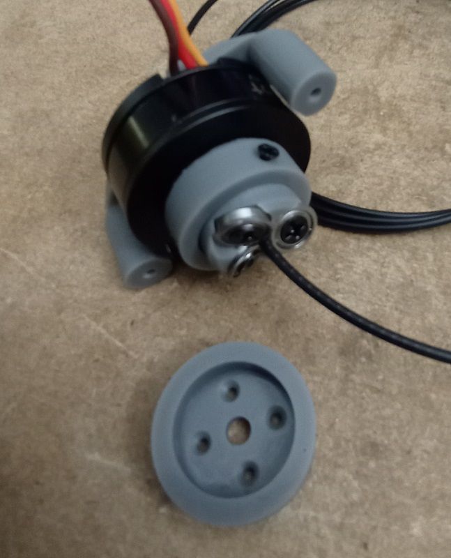
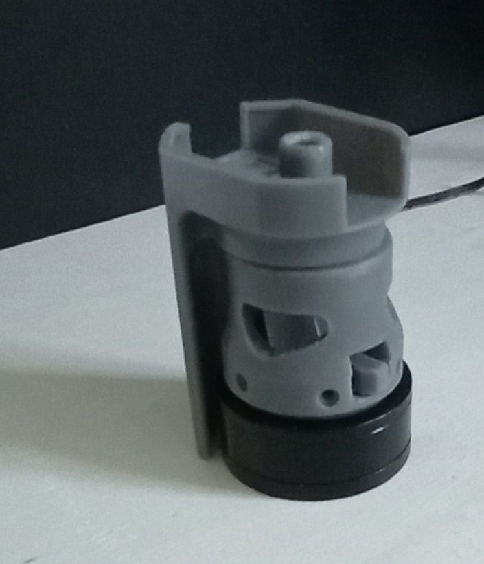
For the BLDC version I had to make a collar for the carrier and added three small screws for clamping the carrier.
@oliof @tombrazier Did you talk to Jason about pressfitting the carrier to the shaft? He might be able to make the shaft-end rougher for a better grip?Tom, I wouldn't be surprised if part of the underextrusion at higher speeds are caused by a slipping carrier?
-
@breed I think they'd work fine. I have found that making the diameter of the flange as large as possible helps with extrusion force. I guess this is because with a larger radius of curvature there is more overlap between flange and filament. As the MF84 is an 8mm OD bearing it will presumably have a flange of a little over 9mm, same as MF85ZZ. When I tried with three MF95ZZ, which have a little over 10mm flange diameter I found the flanges tended to interfere with each other. So both MF85ZZ and MF84 are almost ideal. I say almost because 2 MF95ZZ plus one 9mm flange works and that gives you the most filament overlap possible. But it is asymmetrical, which has its issues.
The major difference between MF84 and MF85ZZ is the inner diameter. With your shoulder screw design this is fine, but for my design I think an inner diameter of 5mm with an M3 screw down the centre of the bearing support is likely to be about the smallest you can go.
-
@o_lampe said in Hollow shaft extruder:
Tom, I wouldn't be surprised if part of the underextrusion at higher speeds are caused by a slipping carrier?
No, I have checked that. The torque requirement is really small and the carrier doesn't come close to slipping even against the full holding torque of the motor. Also, all the underextrusion I have reported has been from compression of the helical thread because it is actually thread pitch that I am measuring.
For the BLDC version I had to make a collar for the carrier and added three small screws for clamping the carrier.
That should work. Another solution, of course, is a slightly redesigned carrier.
Did you talk to Jason about pressfitting the carrier to the shaft? He might be able to make the shaft-end rougher for a better grip?
Very interesting and timely question.
-
@oliof what LDO motor were you getting sampled?
-
@breed hollow shaft motor as specced by @tombrazier for his revision of the VDE.
-
@oliof opp sorry i missed the post with the motor specs. my bad
-
https://www.printables.com/model/565908-screw-extruder
I put my old screw extruder design I had been working on a few years ago and an updated design made for a stepper motor that Ive been working on lately. Im gonna start working on it again, let me know what you guys think. def not as light weight as the VDE100, but was orginally intended to go on a smart effector on my Anycubic Predators. Also at one time I considered remote direct drive as the screw extruder is low torque high rpm and the zesty nimble and such were en vogue at the time.
-
@breed your design reminds me of the roller screw https://en.wikipedia.org/wiki/Roller_screw . One topic would be to solve the twisting force on the filament. If you're using two screws, finding a solution to rotate both in opposite direction would be preferable in my understanding.
There was a 3D printer long ago who used special filament with teeth on it, this would make it easier to get precise movement of the filament. The filament was quadratic in shape instead of round, this can be used to hinder twisting/rotating (analogues to a band saw where the saw is hindered from twisting by using ball bearings top and down of the saw area).
-
@JoergS5 said in Hollow shaft extruder:
lution to rotate both in opposite direction would be preferable in my
i considered that at one time a long time ago haveing two complete assemblys inverted from each other and running in opposite directions to counter act the torque induced into the filament. It might still be a problem. Ive had the titanium screws laying around in a box for years. Im gonna build an assembly and find out. I was gonna try and figure out a way to hinge the backer bearings away from the screw to allow quick release but I dono, I never seem to ever manually insert filament any more, even on my BMG extruder printers I usually just have a macro to jog the filament. i dono.
-
@breed I've build one version of the screw extruder, too. The "skrewder" has 3 screws and their bearings are able to tilt in the holders. I was able to manually load the filament by opening the screws. Then wrap the screws around the filament until they have sufficient grip.
I almost bought me a lathe to make these screws from metal, but it occured to me that the thread pitch and the cant-angle wouldn't cut a single thread in the filament. They only scratch the surface, which is not as reliable as the threading blades of the VDE-100.
It would be a game changer if the screw pitch and cant angle would match. (mass production-wise)
Especially if we could use standard threaded rods. -
@o_lampe How did it work out when you tried driving filament with it? Did it scrub real bad? The problem is that the lead angle for the threads is different between the screw which is say 9-10mm in diameter and the filament which is 1.75.
-
@breed I didn't really try driving it with the motor. The screws are resin printed. But I got a pretty good idea about how tight the wrapper must be to grip the filament.
Much tighter with more threads, obviously.
Maybe It would be a good idea to form a funnel with the three screws, so they can slowly dig deeper in the filament. -
@o_lampe if you think about it, the cant of the screw already does because of the threads lead angle.
-
@JoergS5 said in Hollow shaft extruder:
One topic would be to solve the twisting force on the filament. If you're using two screws, finding a solution to rotate both in opposite direction would be preferable in my understanding.
The same applies the the VDE100 but the torque is so minimal that in practice this is a problem that doesn't need solving. Just the back-torque from the melted end of the filament and the torque coming from the filament winding off the reel are enough to counter the feed torque. Even with TPU! Having a short path through the heatsink also helps because that reduces the amount by which the filament can wind itself up before it gets to the melt zone.
Trying to drive the filament in two different directions with counter-rotating threads / bearing edges will result in (at best) two crossing helical threads on the filament. I have not tried this but my guess is they'd interact in undesirable ways.
-
@breed said in Hollow shaft extruder:
I put my old screw extruder design I had been working on a few years ago and an updated design made for a stepper motor that Ive been working on lately
I reckon that would work with the stepper motor we have specced for the VDE100.
In earlier experiments, rq3 who pioneered the VDE100 used a similar design with threaded rollers. And the fuselabs design does as well. On which topic, does your design by any chance predate 28 October 2019 when fuselabs filed their patent application? And did you public anywhere?
-
@tombrazier It was during COVID but don't remember when it was. I don't think it was that early I'm gonna guess late 2020 early 2021. It was originally for the anycubic predator which came out 2019 I think. It's basically a thread less ballscrew.
-
@tombrazier I made an extruder that used counter rotating nuts to move the filament. The problem with that was the two counter rotating nuts (or whatever cuts threads into the filament) will never grip the filament at exactly the same strength, so one will dominate and the filament will try to twist with it. I found it mainly to be a problem with retracting the filament. If the filament rotates a little when you do a retraction, you won't get the retraction you are expecting. I think you need a bend in the filament path at the input of the extruder to minimize that problem.
See https://drmrehorst.blogspot.com/2021/08/an-old-project-snakebite-extruder.html