Duet3D Logo Duet3D
    • Tags
    • Documentation
    • Order
    • Register
    • Login

    Hollow shaft extruder

    Scheduled Pinned Locked Moved
    General Discussion
    24
    345
    42.6k
    Loading More Posts
    • Oldest to Newest
    • Newest to Oldest
    • Most Votes
    Reply
    • Reply as topic
    Log in to reply
    This topic has been deleted. Only users with topic management privileges can see it.
    • breedundefined
      breed @mrehorstdmd
      last edited by

      @mrehorstdmd That's interesting. I wonder where the 1.75mm came from? I'm assuming 3mm was plastic welding wire originally.

      oliofundefined 1 Reply Last reply Reply Quote 0
      • zero Kundefined
        zero K @mrehorstdmd
        last edited by

        @mrehorstdmd

        A way to increase the filament heating surface sems to be Bondtech/MicroSwiss CTH-Nozzle und e3D high speed Revo.
        No one of my friend is printing 3 mm Filament - this time has gone.

        tombrazierundefined 1 Reply Last reply Reply Quote 0
        • o_lampeundefined
          o_lampe @breed
          last edited by

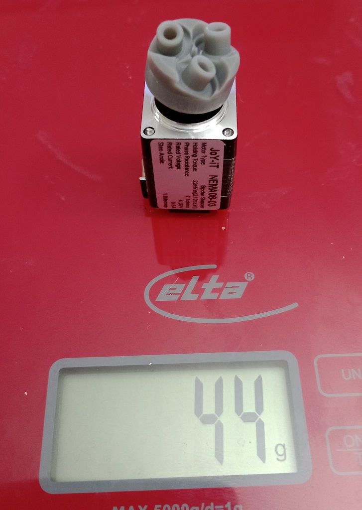
          @breed around 40grams, but it has only 1/10th of the holding torque as Tom already mentioned. It could become interesting for thinner filament or with a planetary gear
          NEMA08.jpg

          1 Reply Last reply Reply Quote 0
          • tombrazierundefined
            tombrazier @zero K
            last edited by

            @zero-K It pushes the point where unmelted filament starts to clog the nozzle to a higher speed. Below that speed my experience with a CHT clone is that it actually increases back-pressure. This is not surprising because increased surface area should be expected to cause increased drag. And with the clone CHTs there is a big flat face in the middle of the 3 holes that almost blocks filament flow. Until you file it away, that is.

            1 Reply Last reply Reply Quote 0
            • tombrazierundefined
              tombrazier
              last edited by

              I have a moment to give the long answer now: the bearings cut a spiral groove around the filament.

              Imagine that groove as a line on a thin straw shape 1.75mm in diameter. If you split the straw lengthwise and flatten it out the helix will become a series of lines sloped at 20° (or whatever the cant angle of the bearings is). The width of the flattened straw is 1.75mm x pi. Hopefully it is fairly easy to see that the vertical distance between each line is therefore tan(20) * 1.75mm * pi. Which is about 2mm.

              For reasons I mentioned above you don't actually get the theoretical pitch. In practice I am presently getting about 1.55mm at "normal" printing speeds (by which I mean anything up to about 100mm/s).

              zero Kundefined 1 Reply Last reply Reply Quote 0
              • zero Kundefined
                zero K @tombrazier
                last edited by

                @tombrazier

                Thank You, now ist der Groschen gefallen - can´t explain in in english.
                I think, I understand it and can find the starting for the setups.

                Greetings
                zero k

                tombrazierundefined 1 Reply Last reply Reply Quote 0
                • tombrazierundefined
                  tombrazier @zero K
                  last edited by tombrazier

                  ist der Groschen gefallen

                  @zero-K Curiously, the phrase translates directly into English and means the same thing. We say "the penny has dropped".

                  1 Reply Last reply Reply Quote 1
                  • oliofundefined
                    oliof @breed
                    last edited by

                    @breed 1.75mm comes from weed trimmer wire IIRC.

                    <>RatRig V-Minion Fly Super5Pro RRF<> V-Core 3.1 IDEX k*****r <> RatRig V-Minion SKR 2 Marlin<>

                    breedundefined 1 Reply Last reply Reply Quote 0
                    • breedundefined
                      breed @oliof
                      last edited by

                      @oliof yep that could be. Didn't think of that.

                      1 Reply Last reply Reply Quote 1
                      • o_lampeundefined
                        o_lampe
                        last edited by o_lampe

                        I couldn't resist and tested the NEMA08 motor with filament:
                        YT-short

                        It looks like it's made for it, but as expected the torque is too low.
                        Maybe with a pushing stationary BLDC motor with limitted torque? SimpleFOC is pretty good with torque control. And the weight of the sensor/driver and step/dir controller (rp2040) wouldn't matter anymore because it's stationary.
                        🤔

                        1 Reply Last reply Reply Quote 0
                        • zero Kundefined
                          zero K
                          last edited by

                          Hi
                          OK, compared with yours, it will be something like a monster hollow shaft extruder.
                          But the first step is done, some parts didn´t arrive yet, may be til next weekend.
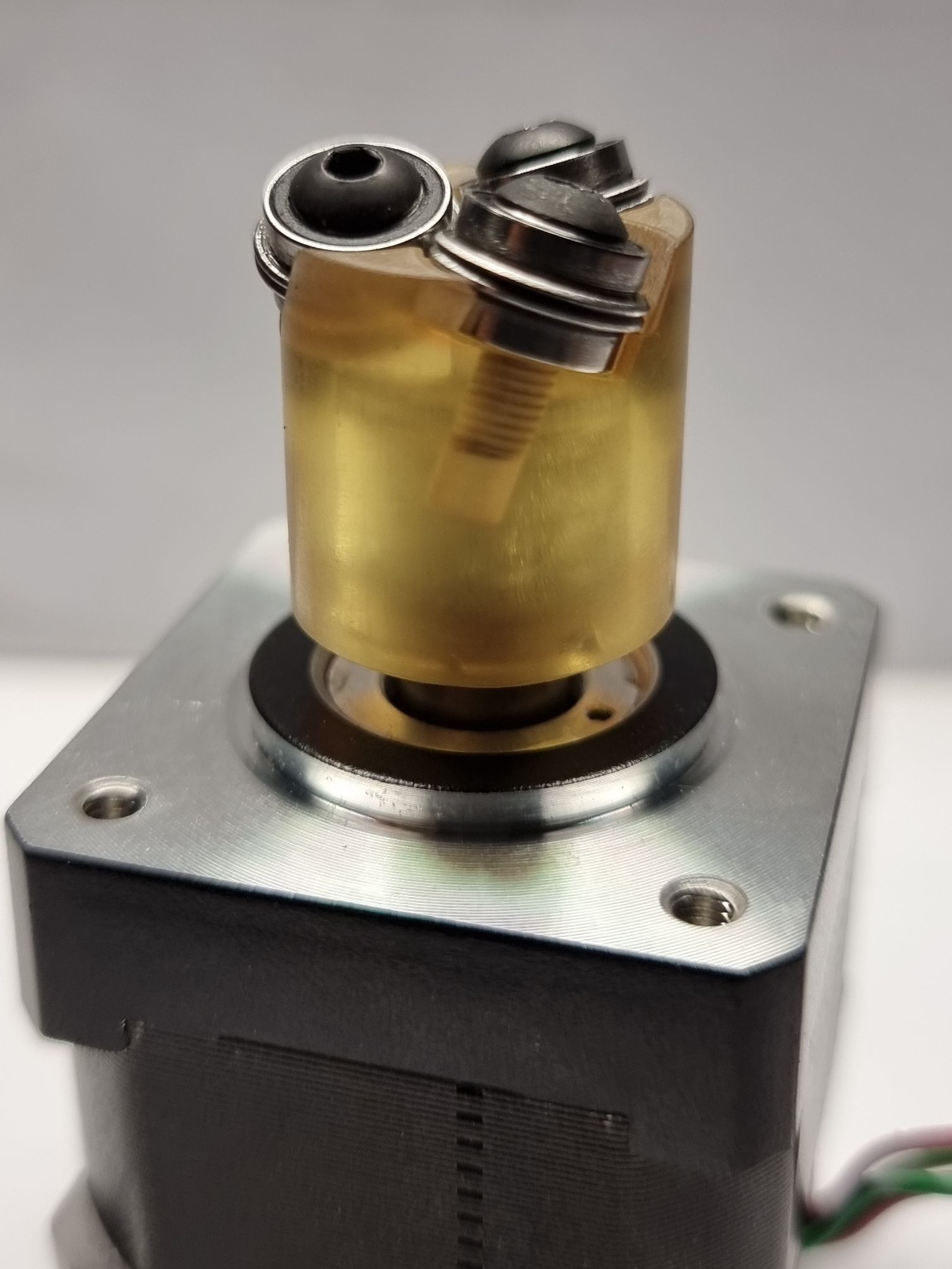
20230903_214822v1.jpg

                          Gruß, zero K

                          1 Reply Last reply Reply Quote 2
                          • breedundefined
                            breed
                            last edited by breed

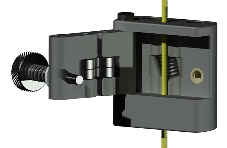
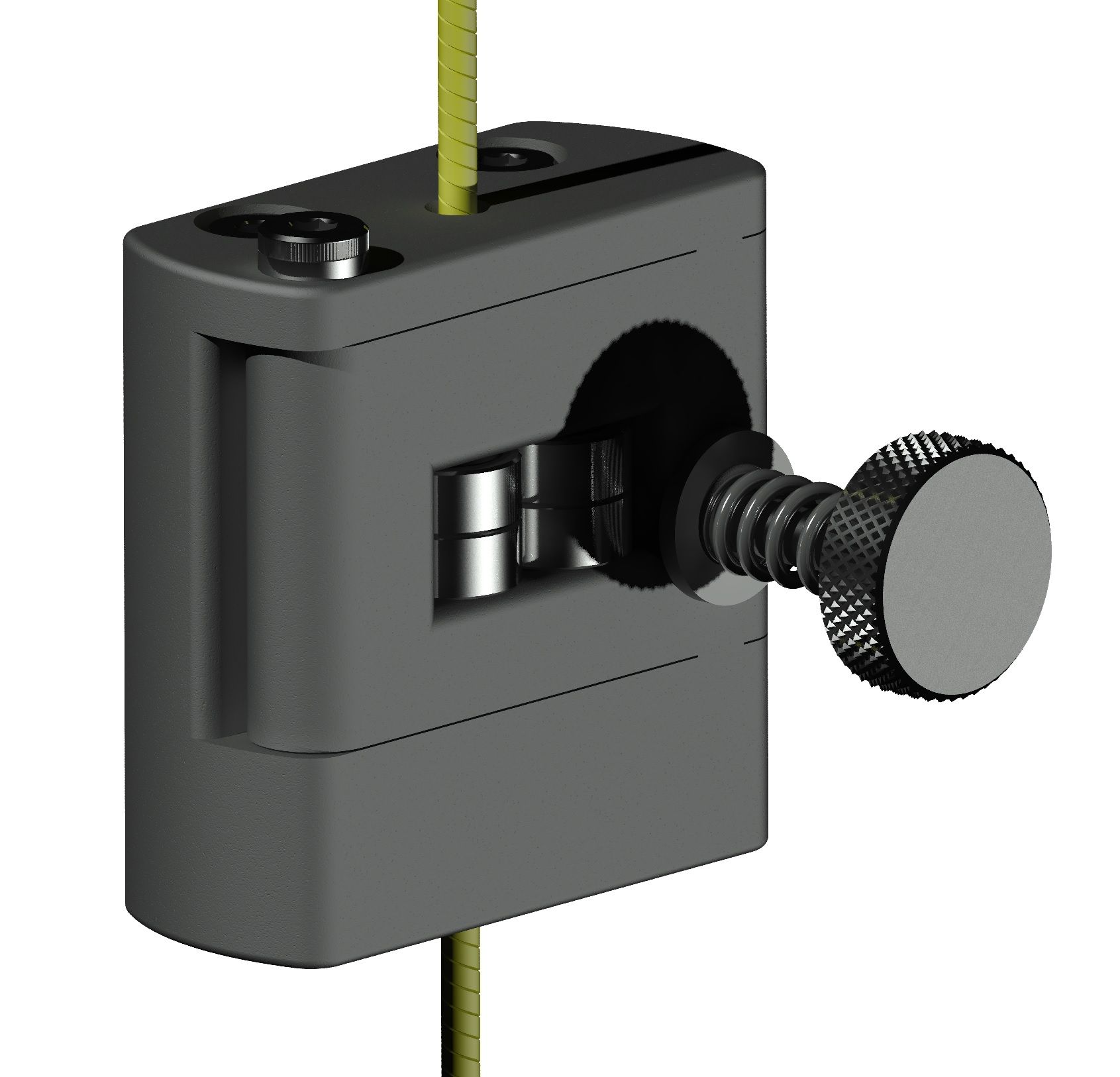
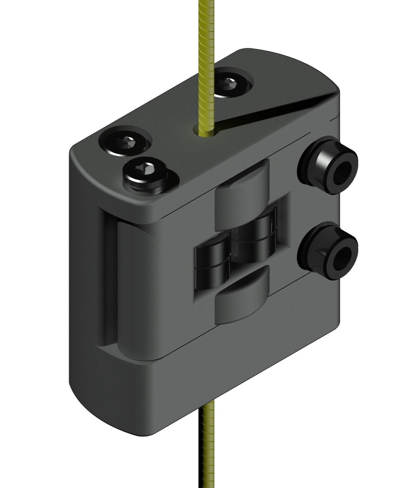
                            Been playing around this week in cad. 8mm roller would have to be made on a lathe. 683 bearings. Would make a 2mm lead 2 start thread on the filament. https://www.printables.com/model/573540-extruder-8mm-quick-release
                            roller extruder 8mm-Temp0001.jpg Untitled.jpg

                            o_lampeundefined 1 Reply Last reply Reply Quote 2
                            • o_lampeundefined
                              o_lampe @breed
                              last edited by o_lampe

                              @breed That's an interesting approach. The front door is very nice!
                              But given the relative high RPM we'd need for extruding, I'd prefer a perfectly balanced design, without the knurled screw.
                              The roller has two bearings inside, I guess , but I don't see a shaft for them?

                              I've made a few suggestions in a quick sketch.

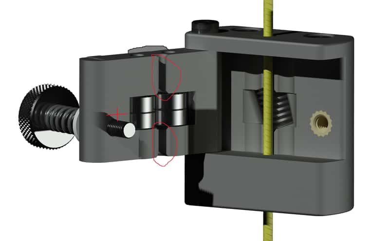
                              • raise the screw to align with the bearings for equal clamping forces ( red cross marks the spot 🙂 )
                              • the cut in the door for the filament is a weak spot in the door. Clamping forces might bend the door and make the bearings contact each other.
                                I enforced the door on the outside to have same thickness all around. ( grey semicircle )

                              roller-extruder-8mm.jpg

                              mrehorstdmdundefined 1 Reply Last reply Reply Quote 0
                              • mrehorstdmdundefined
                                mrehorstdmd @o_lampe
                                last edited by

                                @o_lampe The bearings in the door seem to be misoriented- the filament isn't going to be rotating, is it? Also, the threaded insert in the body is going to get jacked out of the body by the spring force on the screw. I think a nut on the back side of the body would be a better way to go. How are you going to rotate the filament drive screw?

                                https://drmrehorst.blogspot.com/

                                o_lampeundefined 1 Reply Last reply Reply Quote 0
                                • o_lampeundefined
                                  o_lampe @mrehorstdmd
                                  last edited by

                                  @mrehorstdmd said in Hollow shaft extruder:

                                  How are you going to rotate the filament drive screw?

                                  The whole part is mounted on the stepper shaft and rotates. That's why I'm worried about the knurled screw being a substantial offcenter mass...

                                  mrehorstdmdundefined 1 Reply Last reply Reply Quote 0
                                  • mrehorstdmdundefined
                                    mrehorstdmd @o_lampe
                                    last edited by

                                    @o_lampe I see. I thought the screw was the only rotating part. Interesting approach- much easier to fabricate compared to the designs in the posts above.

                                    https://drmrehorst.blogspot.com/

                                    o_lampeundefined 1 Reply Last reply Reply Quote 0
                                    • A Former User?
                                      A Former User
                                      last edited by A Former User

                                      This post is deleted!
                                      1 Reply Last reply Reply Quote 0
                                      • o_lampeundefined
                                        o_lampe @mrehorstdmd
                                        last edited by o_lampe

                                        @mrehorstdmd said in Hollow shaft extruder:

                                        much easier to fabricate compared to the designs in the posts above.

                                        Yes it is, although you'd need a lathe to make the screw. Same problem as most other screw extruder designs.
                                        I'm also unsure, if the pressure bearings add some extra friction, because they don't roll off in line with the filament motion.
                                        All other designs have the same cant angle for all bearings/screws for a reason.

                                        breedundefined 1 Reply Last reply Reply Quote 0
                                        • breedundefined
                                          breed @o_lampe
                                          last edited by

                                          @o_lampe I didn't consider the filament path being a spot where it might flex, that's a good point. The non canted bearings in the door, I considered trying to find a way of adding a 20 degree angle, but then I got to thinking that would decrease the length that the filament is backed and pushed firmly into the groved roller. That length is already limited by the angle of the grooved roller. The shaft for the roller I was intending to be 3mm carbon rod. The bolt and spring for the door is offset because the outer frame is actually 2 pieces so the roller assembly can be inserted. I have a couple different designs I'm playing with in cad and have ordered some sls parts to mess with. Waiting currently on shoulder bolts from China, apparently the boat must be stuck in a canal somewhere. As far as balancing I could prob get it close by calculating up the individual pieces with their specifical gravity and get close. I don't know if I'll try and make this, I might, just figured I'd throw it out for people to think about.

                                          1 Reply Last reply Reply Quote 0
                                          • breedundefined
                                            breed
                                            last edited by breed

                                            Untitled.jpg

                                            updated on printables

                                            o_lampeundefined 1 Reply Last reply Reply Quote 1
                                            • First post
                                              Last post
                                            Unless otherwise noted, all forum content is licensed under CC-BY-SA