Duet3D Logo Duet3D
    • Tags
    • Documentation
    • Order
    • Register
    • Login

    Duet3D announces new tool board at FormNext

    Scheduled Pinned Locked Moved
    General Discussion
    25
    107
    8.8k
    Loading More Posts
    • Oldest to Newest
    • Newest to Oldest
    • Most Votes
    Reply
    • Reply as topic
    Log in to reply
    This topic has been deleted. Only users with topic management privileges can see it.
    • deckingmanundefined
      deckingman @fcwilt
      last edited by

      @fcwilt said in Duet3D announces new tool board at FormNext:

      @Surgikill

      I went and checked the video.

      With the DI attached to the XY gantry how would you tell the what was responsible for whatever reading was displayed? Could not imperfections in the gantry contribute to the reading?

      Thanks.

      Frederick

      You could direct your questions to me rather than via a third party.

      But for sure if the gantry sagged it could imply that the bed was bowed or "dish shaped". My calculations showed that any deflection of the gantry due to the weight of the hot end was insignificant and the rails were known to be straight. But the important thing to note is how flat and level is the build platform with respect to the full range of movement of the nozzle. By fitting the DTi to the gantry where the nozzle is mounted, one is checking both the gantry and the build plate. If there was an unacceptable deviation, then one would carry out further measurements on the individual components to determine where the problem was. But it's a lot quicker to check the entire mechanism in its normal working configuration and only break that down into individual components if an unacceptable deviation is observed.

      Ian
      https://somei3deas.wordpress.com/
      https://www.youtube.com/@deckingman

      1 Reply Last reply Reply Quote 1
      • deckingmanundefined
        deckingman @fcwilt
        last edited by

        @fcwilt said in Duet3D announces new tool board at FormNext:

        @deckingman

        I forgot to ask you what sort of surface do you print on? Directly on the metal plate or something added on top of it?

        Thanks.

        Frederick

        Glass. 6mm thick plane float glass. I learned long ago that the process of having the glass toughened leads to unacceptable distortion. And yes before you ask, I checked the flatness. I've tried most other build surfaces but haven't yet found one that beats plane untreated, "hot swappable" float glass (with a little help from 3DLac now and then) and I'm still using the same 3 sheets that I bought about 7 or 8 years ago.

        Ian
        https://somei3deas.wordpress.com/
        https://www.youtube.com/@deckingman

        1 Reply Last reply Reply Quote 2
        • Surgikillundefined
          Surgikill @fcwilt
          last edited by

          @fcwilt the gantry can contribute or offset the readings. Aluminum extrusion tolerance is terrible, straightness of 0.0125" per foot. Hence why measuring at 5 points and then assuming that those points will simultaneously be the highest and lowest measured points isn't really the right way to go about it. Even measuring the flatness of the build surface while on the machine isn't really correct, because you don't know if it's your gantry or your plate causing the inconsistencies.

          If you are printing at 0.2mm layer height, there is a pretty large variation of z height you can get away with. As you try to increase resolution the problems will begin to show themselves. This is why mesh compensation is used.

          dc42undefined 1 Reply Last reply Reply Quote 1
          • Surgikillundefined
            Surgikill @Surgikill
            last edited by

            @Surgikill said in Duet3D announces new tool board at FormNext:

            @dc42 can you give us the exterior dimensions of the board? I'm trying to see how it will fit in my printer.

            I threw some pictures up in CAD and scaled them, looks like board width is around 45mm without connectors, and board height is around 50mm without connectors.

            1 Reply Last reply Reply Quote 0
            • dc42undefined
              dc42 administrators @Surgikill
              last edited by

              @Surgikill I expect we will publish drawings and models next week.

              Duet WiFi hardware designer and firmware engineer
              Please do not ask me for Duet support via PM or email, use the forum
              http://www.escher3d.com, https://miscsolutions.wordpress.com

              Surgikillundefined 1 Reply Last reply Reply Quote 3
              • o_lampeundefined o_lampe referenced this topic
              • nikschaundefined
                nikscha @elmoret
                last edited by

                @elmoret Nothing stopping you from using a 24V heater at 36V XD
                You'd get 2.25 times more power out of it!
                (and a fire hazard lol)

                Stay in school

                1 Reply Last reply Reply Quote 1
                • Surgikillundefined
                  Surgikill @dc42
                  last edited by

                  @dc42 any update on this?

                  dc42undefined 1 Reply Last reply Reply Quote 0
                  • dc42undefined
                    dc42 administrators @Surgikill
                    last edited by

                    @Surgikill not yet, Tony normally does the drawings and STEP models but he is very busy with Formnext follow-up and SMRRF preparation.

                    Duet WiFi hardware designer and firmware engineer
                    Please do not ask me for Duet support via PM or email, use the forum
                    http://www.escher3d.com, https://miscsolutions.wordpress.com

                    1 Reply Last reply Reply Quote 2
                    • edspedundefined
                      edsped @Surgikill
                      last edited by

                      @Surgikill said in Duet3D announces new tool board at FormNext:

                      @fcwilt said in Duet3D announces new tool board at FormNext:

                      @Herve_Smith

                      You consider the prices to be an issue?

                      The money I spend on hardware is dwarfed by the money I spend on filament.

                      Frederick

                      Toolboards are primarily made for tool changer setups, so multiply your cost difference by the number of toolheads. I'm currently building a tool changer, and each toolhead is going to run me close to $400. At some point, cost becomes a favor. When my toolhead alone is over double the cost of an ender 3 you have to take a step back and reevaluate.

                      I run RRF-36's on my toolchanger and wish I set it up that way sooner.

                      Surgikillundefined gnydickundefined 2 Replies Last reply Reply Quote 1
                      • Surgikillundefined
                        Surgikill @edsped
                        last edited by

                        @edsped those actually look like they might work perfectly. A ton cheaper too.

                        edspedundefined fcwiltundefined 2 Replies Last reply Reply Quote 0
                        • edspedundefined
                          edsped @Surgikill
                          last edited by

                          @Surgikill said in Duet3D announces new tool board at FormNext:

                          @edsped those actually look like they might work perfectly. A ton cheaper too.

                          No issues on my end so far but I have to admit I'm intrigued by the scanning probe but at more than twice the price for the board not sure if it would be worth it.

                          Surgikillundefined 1 Reply Last reply Reply Quote 0
                          • fcwiltundefined
                            fcwilt @Surgikill
                            last edited by

                            @Surgikill said in Duet3D announces new tool board at FormNext:

                            those actually look like they might work perfectly. A ton cheaper too.

                            But they are a funny shape. Who wants a printer with parts that have a funny shape. Give me a good old rectangle every time. 🤣

                            Frederick

                            Printers: a E3D MS/TC setup and a RatRig Hybrid. Using Duet 3 hardware running 3.4.6

                            A Former User? 1 Reply Last reply Reply Quote 0
                            • Surgikillundefined
                              Surgikill @edsped
                              last edited by

                              @edsped Scanning probe would be good. I guess I could have one toolhead with a scanning probe and a euclid probe, and use either depending on the build surface, then do the rest with a fly-rrf-36.

                              @fcwilt 🤣 Although, I do like that most of the connectors are along the bottom edge, and the stepper is along the top. Connectors along the sides have been a real pain for me designing slim toolheads so I can increase tool capacity.

                              1 Reply Last reply Reply Quote 1
                              • A Former User?
                                A Former User @fcwilt
                                last edited by

                                @fcwilt My Orbiter extruders have the same funny shape at the back thanks to their NEMA14 stepper so I am set. And it is amazing how you can hide the funny boards shape inside an enclosure so the one on the NEMA17 does not need a sheet thrown over it if companies is over.

                                1 Reply Last reply Reply Quote 1
                                • edspedundefined
                                  edsped
                                  last edited by

                                  I actually like the shape and as has already been said, having connectors on all 4 sides seems like it would add clutter. For me the RRF-36's are nice and compact. I'll likely grab the step file when it's released and see how it compares though.
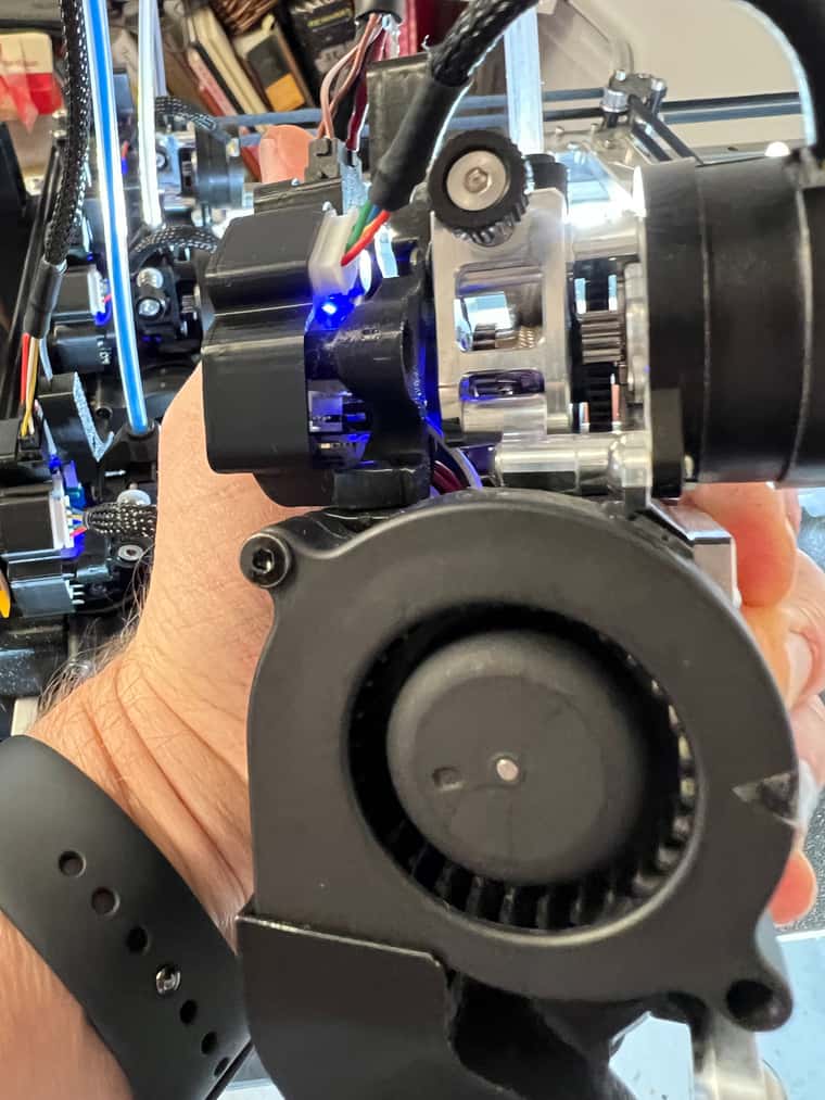
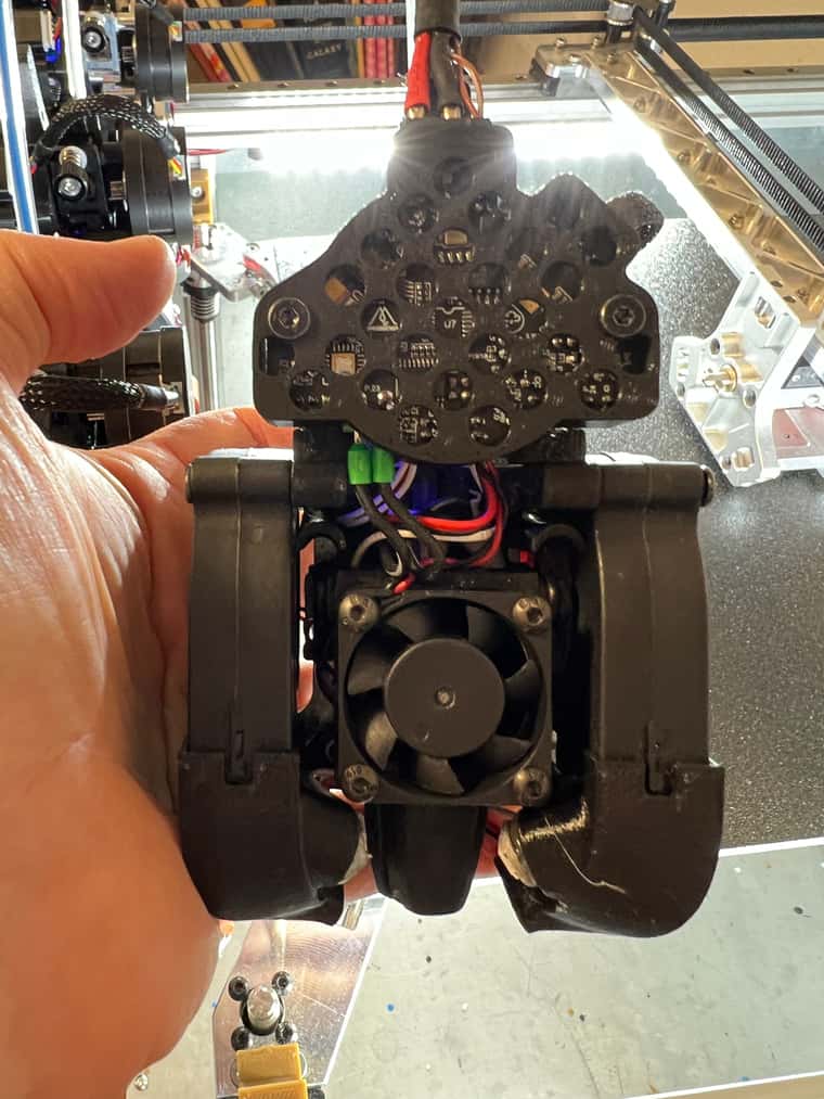
                                  IMG_2115.JPG IMG_2114.JPG

                                  fcwiltundefined 1 Reply Last reply Reply Quote 0
                                  • fcwiltundefined
                                    fcwilt @edsped
                                    last edited by

                                    @edsped

                                    I was just making a funny remark about the shape.

                                    I assume it is shaped that way to fit something else.

                                    So what is that "something else"?

                                    Thanks.

                                    Frederick

                                    Printers: a E3D MS/TC setup and a RatRig Hybrid. Using Duet 3 hardware running 3.4.6

                                    jay_s_ukundefined 1 Reply Last reply Reply Quote 0
                                    • jay_s_ukundefined
                                      jay_s_uk @fcwilt
                                      last edited by

                                      @fcwilt the RRF-36 is shaped to mount on the rear of a nema 14

                                      Owns various duet boards and is the main wiki maintainer for the Teamgloomy LPC/STM32 port of RRF. Assume I'm running whatever the latest beta/stable build is

                                      fcwiltundefined 1 Reply Last reply Reply Quote 0
                                      • fcwiltundefined
                                        fcwilt @jay_s_uk
                                        last edited by

                                        @jay_s_uk said in Duet3D announces new tool board at FormNext:

                                        @fcwilt the RRF-36 is shaped to mount on the rear of a nema 14

                                        There must be more to that. A NEMA 14 is square. The RRF-36 is not.

                                        Frederick

                                        Printers: a E3D MS/TC setup and a RatRig Hybrid. Using Duet 3 hardware running 3.4.6

                                        jay_s_ukundefined A Former User? 2 Replies Last reply Reply Quote 0
                                        • jay_s_ukundefined
                                          jay_s_uk @fcwilt
                                          last edited by

                                          @fcwilt round nema 14's aren't square... https://www.omc-stepperonline.com/round-nema-14-bipolar-0-9deg-8ncm-11-33oz-in-0-65a-36x20mm-4-wires-14hr08-0654s
                                          they're now also the most popular type of motor to use on an extruder

                                          Owns various duet boards and is the main wiki maintainer for the Teamgloomy LPC/STM32 port of RRF. Assume I'm running whatever the latest beta/stable build is

                                          fcwiltundefined 1 Reply Last reply Reply Quote 1
                                          • fcwiltundefined
                                            fcwilt @jay_s_uk
                                            last edited by

                                            @jay_s_uk

                                            Well now it makes some sense.

                                            Thanks.

                                            Frederick

                                            Printers: a E3D MS/TC setup and a RatRig Hybrid. Using Duet 3 hardware running 3.4.6

                                            1 Reply Last reply Reply Quote 1
                                            • First post
                                              Last post
                                            Unless otherwise noted, all forum content is licensed under CC-BY-SA