Issues with pressure advance since RRF 3.4
-
@gloomyandy I'm sure you are right in that the angle between line segments plays a part. The description of M566 states (quote) ....
"The model files and GCode files used by repraps generally render circles and other curves shapes as a sequence of straight line segments. If the motors were not allowed any instantaneous speed change, they would have to come to a stop at the junction between each pair of line segments. By allowing a certain amount of instantaneous speed change, printing speed can be maintained when the angle between the two line segments is small enough."
So if we knew how the algorithm worked, then maybe we can determine that the optimum jerk value would be the lowest value which maintains the print speed around a segmented curve? The question is, how many segments or more precisely the angle between them. Thoughts?
-
@gloomyandy So by way of a bit of additional data, I've just run a couple of simple prints. On the basis that I wanted a large angle between segments but not 90 degrees, I made a 200mm diameter, 5 sided hollow "cylinder" with 3mm thick walls. Sliced at 80mm/sec with 3 perimeters (inside and out) that gives 6 perimeter lines using a 0.5m nozzle with no other infill. Then I printed it and played around with M566 on the fly. My default is 1500 for X and Y and that's what I started with. Going higher leads to an audible "clunk" on direction change. This could be more problematic for less robust printer designs. Going lower does have an impact on speed but it's subtle. DWC doesn't update all that fast but I could detect the odd value for top speed which was lower than 80. No such low values could be detected at 1500 Jerk and above.
So maybe that's one strategy for setting jerk. Print a large 5 sided hollow "cylinder" and increase jerk until the machine "clunks", then back off a bit.
As promised, these are the values that work best for me on my machine/
M566 X1500 Y1500 Z300 E3600 M201 X1000 Y1000 Z300 E6000 M203 X21000 Y21000 Z780 E9000 -
@deckingman Interesting! Was the clunk during the printing of the "curve" (rather than at one end)? How much lower did you need to go before you saw a noticeable drop in speed?
From my (rather vague) recollection of school geometry the length of the "sides" does not impact the angle but the number of "sides" does. With 5 sides the angle will be 72degrees with 10 "sides" it would be 36degrees. I'd expect you to be able to use a lower jerk for similar results with a 10 sided object.
If the jerk setting is too low such that the target speed can't be maintained then the length of the sides will start to have an impact as that will (eventually) determine the maximum speed that can be reached between each "corner".
I wonder if a test print which had a large number of "sides" at the base and reduced that number as the height increased would provide a useful insight into how this works on a particular printer?
Maybe we should start a new thread to continue this discussion?
-
@deckingman So if I'm looking at this correctly your settings are counter to the high accel low jerk recommendations for proper
PAinput shaping given elsewhere? I thought, for the CoreXY at least Jerk should have been somewhere around 300 mm/min. -
@gloomyandy said in Issues with pressure advance since RRF 3.4:
@Notepad Are the jerk and acceleration figures you are quoting for the extruder, the movement axis or both?
Those were in relation to extruder jerk and accel settings.
For printing I generally use the following: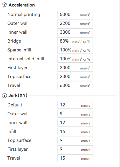
For the actual requested print speeds, the issue is identical if asking for 40mm/s or 300mm/s. As for the printers Jerk and Accel values, these were determined by vibrational analysis and reinforced with real world ABX testing on a unified test print - so I am confident in saying the printer is behaving as intended, isolating the problem to either the extruder, the extrusion control algorithm, or the nozzle flow in general.
I should say, this isnt isolated to one machine, I currently have 5 similar machines behaving the same, and it only becomes apparent on the 0.6mm nozzles and above.
The real bamboo printer manufacturer
-
@edsped Jerk depends on the printers rigidity, If your printer can do X jerk without it inducing vibrations or warp, then you need to go up to that value but no further.
I have identified a weird behaviour with RRF and low jerk, but I believe this will be resolved once IS is done on small line segments.
-
@gloomyandy said in Issues with pressure advance since RRF 3.4:
@deckingman Interesting! Was the clunk during the printing of the "curve" (rather than at one end)?
No the "clunk" was at the intersection of the two segments. i.e. where the direction changed. I didn't actually notice any adverse effects on the print quality but clearly a near instantaneous change of direction for a moving mass is going to sound "clunky". Bear in mind that a 200mm dia pentagon has longish sides (so big segments) and also my "all metal" gantry is on the heavy side. I did go silly high (up to 6000 jerk) and while the "clunk" was more audibly pronounced, I couldn't really detect any difference in overall speed.
How much lower did you need to go before you saw a noticeable drop in speed?
Well you have to look hard to notice the drop in speed but basically anything less than 1500 jerk did have an effect. 1500 mm/jerk is 25 mm/sec and I was printing at 80mm sec. In theory one would expect the move to decelerate to the jerk speed, then change direction but that's clearly not what happens - even with a biggish change in direction of 72 degrees.
From my (rather vague) recollection of school geometry the length of the "sides" does not impact the angle but the number of "sides" does. With 5 sides the angle will be 72degrees with 10 "sides" it would be 36degrees. I'd expect you to be able to use a lower jerk for similar results with a 10 sided object.
I tried 5, 6 8 and 12 sided "cylinders". I can't say that I could detect any difference and there was still a very slight drop in overall speed with a 12 sided "cylinder" and with jerk values lower than 1500 (which is surprising).
If the jerk setting is too low such that the target speed can't be maintained then the length of the sides will start to have an impact as that will (eventually) determine the maximum speed that can be reached between each "corner".
I'd have thought that acceleration would have a much bigger impact on attaining target speed.
I wonder if a test print which had a large number of "sides" at the base and reduced that number as the height increased would provide a useful insight into how this works on a particular printer?
I use OpenScad so to do a 5 sided "cylinder", I used $fn =5 which sets the number of segments. But there is another variable that I've never played with which is $fs. That sets the segment size. So if made a cone with fixed $fs insteda of $fn, then in theory it should have a large number of segments at the base reducing as the height increases. I might give that a go some time.
Maybe we should start a new thread to continue this discussion?
We do seem to have hijacked this thread.
-
@edsped said in Issues with pressure advance since RRF 3.4:
@deckingman So if I'm looking at this correctly your settings are counter to the high accel low jerk recommendations for proper
PAinput shaping given elsewhere? I thought, for the CoreXY at least Jerk should have been somewhere around 300 mm/min.Dunno. I don't get ringing so I don't really have a need to use input shaping. Maybe it's my approach of trying to maintain as near constant speed as possible or maybe it's just having a very rigid but somewhat heavy hot end assembly. I did have a play around with the accelerometer built into my tool board but the graphs don't give me any defined frequency peak that I could use as a centre frequency. Such peaks as there are seem to be at around 30, 50 and 90 Hz but they are low in amplitude and difficult to discern.
-
@gloomyandy So here is a bit more data. If in doubt - do the maths I always say. Starting with the formula v=u+at where v=initial velocity, u= final velocity, a=acceleration and t=time, we can rearrange that to give t=(v-u)/a. So with the print above at 80mm/sec, if it did indeed decelerate at 1000mm/sec^2 from 80mm/sec to the jerk speed of 25 (1500mm/minute) then the time it takes would be 0.055 seconds for that phase. Then we have the change of direction followed by an acceleration at the same rate from 25 to 80 mm/sec. So the total deceleration/acceleration phase takes (0.55 x 2 = ) 0.11 seconds. That would explain why it's difficult to detect and change in overall speed. We can also calculate the distance travelled which worked out at 2.8875 mm - again difficult to spot by eye.
Now it gets interesting. If we change the final velocity to zero (i.e. no jerk) then the time it takes decelerate from 80mm/sec to zero speed at 1000mm/sec^2 is 0.08 seconds (as opposed to 0.055 with 1500 mm/minute jerk) so 0.16 seconds for both the accel and decel phases.
So the impact on print speed will only be apparent where there are a large number of segments. If we assume our cylinder had 360 segments (one per degree) and also assuming that each segment is long enough to reach the desired speed, then the time "lost" decelerating and accelerating would be (360 * 0.16 = ) 57.6 seconds. Whereas with jerk set to 1500 (25mm/sec) then the time "lost" becomes (360 * 0.11 = ) 39.6 seconds. As an aside, it has been mentioned that jerk should be set to circa 300 which would be 5mm/sec giving the "time lost" as 54 seconds which isn't much different to having no jerk at all.
Now, there are other factors at play because I mentioned that the distance travelled was 2.8875 mm to go from 80mm/sec to 25mm/sec at 1000mm/sec^2. With my 200mm diameter cylinder, 360 segments would each have a length of 1.745mm so they would be too short and 80mm/sec wouldn't be achieved. We'd need to drop the number of segments to around 110. So using the above calculations but with 110 segments, the "time lost" would be 12.1 seconds with jerk at 1500 (25mm/sec) and 17.6 seconds with zero jerk.
Finally, the circumference of a circle 200mm in diameter is circa 628mm. Printing 628 mm at 80mm/sec should take 7.855 seconds if it was a pure X or Y move. If we add the "time lost", we get 19.9 seconds with 1500 jerk or 25.5 with zero jerk so roughly 28% faster for one circumference but it's very much acceleration dependent.
I guess it's fair to say therefore that the higher the acceleration, the less need for jerk (because the "time lost" due to acceleration/deceleration will be less). Or rather the "time lost" could be the same with high acceleration/low jerk or low acceleration/high jerk. Of course, "time lost" isn't by any means the only factor that determines print quality but if you want to run near constant speed then low acceleration/high jerk is the way to go (in my humble opinion).
Now I'll sit back and wait for the pedants to find the flaws in my maths or reasoning (of which there could be many)........
-
@Notepad I'll have to dig but my recollections is as low a jerk for X & Y as possible for IS to work properly. That number being somewhere in the neighborhood of 5 - 6 mm/s. I'm trying to follow my academic training and always use units to keep things clear. This was recently posted so I should be able to find a link to the thread when I'm home.
-
@deckingman
Let me have a go at explaining what I understand about how jerk is applied in RRF....First consider a set of moves
G1 X10
G1 X20
G1 X30
Let's assume the feedrate, and acceleration are such that the length of each move is enough for the target speed to be easily reached. So the simple case would give us three moves each of which accelerates(a), then cruises(c) at the target speed then decelerates(d) back to zero. so we would have
a/c/d a/c/d a/c/dHowever RRF would like to make the overall motion as smooth and fast as it possibly can. This is pretty easy in this case as we can in effect cancel out some of the acceleration and deceleration phases and extend the cruise phases so then we get:
a/c c c/d
Which is a much smoother overall move. So far so good!We now need to look at what actually happens in a move like those above, let's assume we have a simple Cartesian motion system. With that system the above set of moves would have the X motor operating at the feedrate and the Y motor not moving. So 100% of the move speed is allocated to X and 0% to Y.
Now suppose that instead of a set of simple moves along the same axis we are creating a shallow "curve" from a series of straight lines. The curve is such that the first move is 100% X 0% Y, the second move is 90% X and 10% Y (we will ignore later moves to keep things simple). Can we still smooth these moves out in some way? This is when jerk comes into the picture. Let's assume the feedrate is 100mm/s and that the jerk limit is set at 20mm/s (for both X and Y). So what we are saying is that the system is such that we can have an instantaneous change in speed so long as the change is less than the jerk limit. In this example at the join between the first move and the second the change in speed for X is -10mm/s ( a 10% reduction of speed from 100mm/s), for Y we have a +10mm/s change in speed (as it needs to go from 0mm/s to 10% of 100mm/s). In both cases these changes are below the jerk limit of 20mm/s so we can still merge them and maintain "smooth" motion (though the motors will see a jump in speed).
If we have a sharper join between two of the moves such that the first move speed was 100% X and 0% Y but this time the second was 70% X and 30% Y then things become more interesting. Now we have a decrease in speed for X of -30mm/s and an increase in speed of Y of +30mm/s in both cases this exceeds our jerk limit, we need to adjust the speed at the join so we reduce our target velocity for the end of the first move to be 66.67mm/s (instead of 100mm/s). Now the jerk is 0.3*66.67 = 20mm/s so within our jerk limits. However because we have had to reduce the speed at the join we now need to have a deceleration section to the first part of the move and an acceleration to the second part of the move so our motion is no longer smooth.
The above is a big simplification of what actually happens (in particular I've played very fast and loose with the % speed model, in reality this is a direction vector that is normalised) but I think it captures the basic mechanism. The key function in applying jerk is matchSpeeds see here: https://github.com/Duet3D/RepRapFirmware/blob/3.5-dev/src/Movement/DDA.cpp#L1249
From the above I hope we can see that having low jerk and high acceleration will mean that there is less chance to smoothly join consecutive moves, instead you get a series of (in this case) fast decelerations and accelerations which is likely to make the motion noisy and induce vibration.
What I'm not sure about is the impact of high jerk on things like IS, PA and retraction.
-
@gloomyandy
Well written mate -
@Notepad I am not surprised at all that PA and Retraction behave wildly different on 0.6 and larger nozzle sizes. 0.6 nozzle already have double the area of a 0.4, which means pressure buildup, polymer viscosity, "sticking to itself", and gravity have a much larger amount of stuff to deal with for easy control.
This gets ridiculously obvious when using 2mm nozzles where common retraction basically does nothing, and you need to switch to long wipes and then short retracts/long unretracts for acceptable results (Cura's new gradual flow plugin might help).
<>RatRig V-Minion Fly Super5Pro RRF<> V-Core 3.1 IDEX k*****r <> RatRig V-Minion SKR 2 Marlin<>
-
@gloomyandy I think we came to the same conclusion but from different angles. You say that low jerk/high acceleration gives less smooth motion because of the series of accels/decels before each segment boundary, while I concluded that the same combination would give less constant speed which is essentially the same thing.
Regarding input shaping, (this is going to be contentious) as I understand it, people are saying that it works best with low jerk/high acceleration. But from what we have both concluded it is this combination that results in a series of sharp accels/decels which in itself is more likely to induce ringing. So by setting low jerk/high acceleration are people inducing ringing in order to use IS to combat it?
I can test this theory. I don't get ringing but I recently played around with the accelerometer built in to my tool board just because I could. But I could find no definable peak to use as a centre frequency. I can repeat those tests with low jerk/high accel.
Edit. That ain't gonna work because IIRC, each move starts at zero speed so jerk won't get applied.
-
@oliof said in Issues with pressure advance since RRF 3.4:
@Notepad I am not surprised at all that PA and Retraction behave wildly different on 0.6 and larger nozzle sizes. 0.6 nozzle already have double the area of a 0.4, which means pressure buildup, polymer viscosity, "sticking to itself", and gravity have a much larger amount of stuff to deal with for easy control.
This gets ridiculously obvious when using 2mm nozzles where common retraction basically does nothing, and you need to switch to long wipes and then short retracts/long unretracts for acceptable results (Cura's new gradual flow plugin might help).
Yes, I found exactly the same thing when I took two years out of my life building experimental hot ends. The other thing that buggers everything up is the volume of molten material which acts like a kind of sponge and damps out pressure variations. With a high volume of molten material, any short sharp extruder moves get damped out into a kind of slowly changing pressure at the nozzle which makes it impossible to print fine details.
-
The fact that printing curves composed of linear segments requires moderately high jerk, but input shaping is somewhat defeated by jerk, is the reason that the real path forward is by using look-ahead / path smoothing, as I asked about here:
https://forum.duet3d.com/topic/32942/progress-on-path-smoothing-lookahead
So, get in there and voice your support.
The only other approach that would work is to have true arc support (RRF just decomposes arcs into relatively coarse linear segments, currently), and reliable arc fitting in the slicer (none that I am aware of, currently).
-
@CCS86 said in Issues with pressure advance since RRF 3.4:
...................The fact that printing curves composed of linear segments requires moderately high jerk.............................,
Well actually the jerk required to print curves kind of depends...............To elaborate, I printed a few more test parts today. They were nice big hollow cylinders, 360mm in diameter with 3mm thick walls and 3 perimeters meaning that the infill lines were the same as the perimeter - i.e 6 complete turns around for each layer. To start with, I wanted to try something with obvious facets so I used the variable $fs=5 in OpenScad which according to the documentation should have given a segment length of 5mm. In reality, I ended up with facets (segments) that were about 35mm long. So about 32 segments around the circumference giving an angle between segments of about 11 degrees. I printed this at 80mm/sec with my usual 1000mm/sec^2 accel and 1500mm/min jerk. then I progressively reduced jerk. The initial layer time was 1min 26 secs. At 1000 jerk everything was much the same. At 500 jerk, the motion was observed to be less fluid and I could clearly detect changes of speed before and after each segment boundary. But print quality seemed OK. At 300 jerk, the motion was much less fluid, the changes in speed either side of the segment boundaries was quite pronounced and the layer time increased to 1min, 30 secs (so overall about 4.6 percent slower).
But then I made another cylinder with a very high segment count ($fn=300 in OpenScad). At this setting, the stl looks smooth rather than faceted. I printed this as before but this time, I could go below jerk of 300 with no noticeable change in top speed and the movement was still fluid. I kept reducing jerk and at 100 things were the same as they were at 1500 - no detectable difference in reported speed or layer time and visually and audibly it looked the same. Only when I reduced jerk to below 100 did things start to look and sound pretty awful.
So it seems to me that if curves have sufficiently small segments sizes, then a low jerk value can indeed be used. The lower the number of segments (or the higher the angle between them) then the higher jerk needs to be to maintain fluid motion and near constant speed.
The only other approach that would work is to have true arc support (RRF just decomposes arcs into relatively coarse linear segments, currently), and reliable arc fitting in the slicer (none that I am aware of, currently).
The problem with that is that stepper motors are effectively digital devices. That is to say, even if you could produce some sort of "true arc", it still needs to be broken down into motor steps which effectively gives you linear segments (albeit small ones).
-
That's one very specific case you tested.
80 mm/s is relatively slow and on a large arc at a slow speed, of course you can reduce jerk significantly, with a finely faceted model.
Things will be different with higher speeds and smaller arcs. All sorts of real world printing scenarios that need to be balanced.
Your point about motor steps being linear is really a moot point. Every CNC machine has a minimum increment of movement, including the most precise, like a wire EDM. These increments are so small, that practically, they are invisible on the finished part. In our application, the issue is with large linear segments interrupting the motion controller's flow. By looking ahead, we can start the change in axis movement speed ahead of the junction, so there isn't such a reliance on jerk, creating much smoother motion.
-
@CCS86 That test was just a follow up to the other tests that I've posted and we are looking exclusively at jerk - specifically should we use low jerk, high acceleration or high jerk / low acceleration. Of course there are an almost infinite number of scenarios and we don't yet have a full understanding of how the jerk setting works with PA and IS. I've simply been trying to add more data points to add to our understanding.
I'll stop my investigations now or keep the results to myself, as there is little point continuing if people are going to take the results out of context and dismiss them out of hand.
-
@deckingman why are you taking this so personally?
You seemed to be suggesting that low jerk could be used generally. I pointed out that your test was very specific an not representative of general printing. Not sure why that would offend you.