1LC TOOLBOARD v1.1. Accelerometer fail
-
Hi,
I have a 1LC toolboard v1.1 with firmware 3.5.0-RC.1 connected to a DUET3 MB6HC.
The input shaping addon show this error when trying to record a motion profile. "Error: Failed to start accelerometer data collection: INT1 error"
I read this happens beacuse this revision of the board have a missing diode. Its posible to solder this diode and what reference is needed?
I have another error with my filament switch sensor connected to the board, when i try to activate it the board resets all the time. Is it possible that this error also has some relationship with the diode? This is the command i use to activate the sensor: M591 D0 P1 C"121.io1.in" S1Thanks.
-
@Isaac-López Please share your full config.g here.
Duet software engineer
-
This is my config.g.
The error message when the firmware resets because the filament sensor configuration is "DCS has been stoped"; Configuration file for Duet 3 (firmware version 3) ; executed by the firmware on start-up ; ; generated by RepRapFirmware Configuration Tool v3.1.4 on Wed Aug 05 2020 18:14:45 GMT+0200 (hora de verano de Europa central) ; General preferences M80 C"pson" ; Turns on the ATX power supply G90 ; send absolute coordinates... M83 ; ...but relative extruder moves M550 P"Duet 3" ; set printer name M669 K1 ; select CoreXY mode G4 S1 ; wait for expansion boards to start M955 P121.0 I10 ; Configure Accelerometer ; Drives M569 P0.0 S1 ; physical drive 0.0 goes forwards M569 P0.1 S1 ; physical drive 0.1 goes forwards M569 P0.2 S0 ; physical drive 0.2 goes forwards M569 P0.3 S1 ; physical drive 0.3 goes forwards M569 P0.4 S0 ; physical drive 0.4 goes forwards M569 P121.0 S0 ; physical drive 121.0 goes forwards M584 X0.1 Y0.0 Z0.2:0.4 E121.0 ; set drive mapping M671 X-63:368 Y0:0 S5 ; leadscrews at left (connected to Z) and right (connected to E1) of X axis M350 X16 Y16 Z16 E16 I1 ; configure microstepping with interpolation M92 X100.00 Y100.00 Z400.00 E655 ; set steps per mm M566 X500.00 Y500.00 Z24.00 E600.00 ; set maximum instantaneous speed changes (mm/min) M203 X25000.00 Y25000.00 Z1200.00 E7200.00 ; set maximum speeds (mm/min) M201 X20000.00 Y20000.00 Z300.00 E800.00 ; set maximum accelerations (mm/s^2) M204 P8000 T14000 ; set printing and travel accelerations M906 X1200 Y1200 Z1200 I30 ; set XYZ motor currents (mA) and motor idle factor in per cent M906 E1200 I10 ; set Extruder motor currents (mA) and motor idle factor in per cent M84 S30 ; Set idle timeout ; Pressure advance M572 D0 S0.035 ; Pressure advance ; Linear Compensation ;M592 D0 A0.015 B0.0012 L0.2 ; ; Dynamic Acceleration Adjustment M593 P"zvd" F25 ; Axis Limits M208 X-9 Y0 Z0 S1 ; set axis minima M208 X320 Y310 Z350 S0 ; set axis maxima ; Endstops M574 X1 S1 P"121.io2.in" ; configure active-high endstop for high end on X via pin io3.in M574 Y2 S1 P"io2.in" ; configure active-high endstop for high end on Y via pin io2.in M574 Z1 S2 ; configure Z-probe endstop for low end on Z ;Sensorless homing config ;M915 X S3 R0 F0 ; Z-Probe M950 S0 C"121.io0.out" ; create servo pin 0 for BLTouch M558 P9 C"121.io0.in" H3 F300 T20000 ; set Z probe type to bltouch and the dive height + speeds G31 P25 X-25 Y-15 Z1.6 ; set Z probe trigger value, offset and trigger height (+valor +bajo) M557 X30:270 Y30:270 P6:6 ; define mesh grid ; Heaters M308 S0 P"temp0" Y"thermistor" T100000 B3950 ; configure sensor 0 as thermistor on pin temp0 M950 H0 C"out0" T0 ; create bed heater output on out0 and map it to sensor 0 M307 H0 B0 S1.00 A140.1 C400.1 D6.8 V24.2 ; disable bang-bang mode for the bed heater and set PWM limit M140 H0 ; map heated bed to heater 0 M143 H0 S130 ; set temperature limit for heater 0 to 130C M308 S1 P"121.temp0" Y"thermistor" T100000 B4725 C7.06e-8 ; configure sensor 1 as thermistor on pin temp1 M950 H1 C"121.out0" T1 ; create nozzle heater output on out1 and map it to sensor 1 M307 H1 B0 R2.434 C196.7:173.0 D4.89 S1.00 V25.2 ; disable bang-bang mode for heater and set PWM limit M143 H1 S280 ; set temperature limit for heater 0 to 280C ; Fans M950 F0 C"121.out1" Q500 ; create fan 0 on pin out7 and set its frequency M106 C"Layer" P0 S0 H-1 ; set fan 0 value. Thermostatic control is turned off M950 F1 C"121.out2" Q500 ; create fan 1 on pin out8 and set its frequency M106 P1 S1 H1 T55 ; set fan 1 value. Thermostatic control is turned on M950 F2 C"out9" Q500 ; create fan 2 on pin out6 and set its frequency M106 C"Filtro" P2 S0 H-1 ; set fan 2 value. Thermostatic control is turned off ; Tools M563 P0 S"EVA2" D0 H1 F0 ; define tool 0 G10 P0 X0 Y0 Z0 ; set tool 0 axis offsets G10 P0 R0 S0 ; set initial tool 0 active and standby temperatures to 0C ;Filament Sensor M591 D0 P1 C"121.io1.in" S1 ; Custom settings are not defined M564 H0 ;Allow Moving Axes Without Homing ; Miscellaneous M575 P1 S1 B57600 ; enable support for PanelDue M575 P2 S1 B57600 ; enable support for Neopixels M911 S20 R21 P"M913 X0 Y0 G91 M83 G1 Z3 E-5 F1000" ; set voltage thresholds and actions to run on power T0 ; select first tool -
@chrishamm The filament monitor is working fine with the new firmware 3.5.RC2, but the accelerometer continue showing the same error. My config.g is posted above.
-
@Isaac-López
The boards were modified during production by- the INT output of the accelerometer is no longer connected to PA19 of the microcontroller;
- INT is instead connected through a silicon diode to PA00.
To do this yourself, you need a 1N4148W (SOD123 package) diode. Then, on the toolboard:
- Cut the trace between the PA19_sel pads
- Solder the diode between PA19_sel pad and the PA0 pad.
- The end with the stripe goes to the PA19 pad.
A couple of pictures:
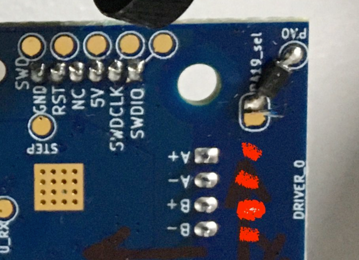
(source: https://forum.duet3d.com/post/232831)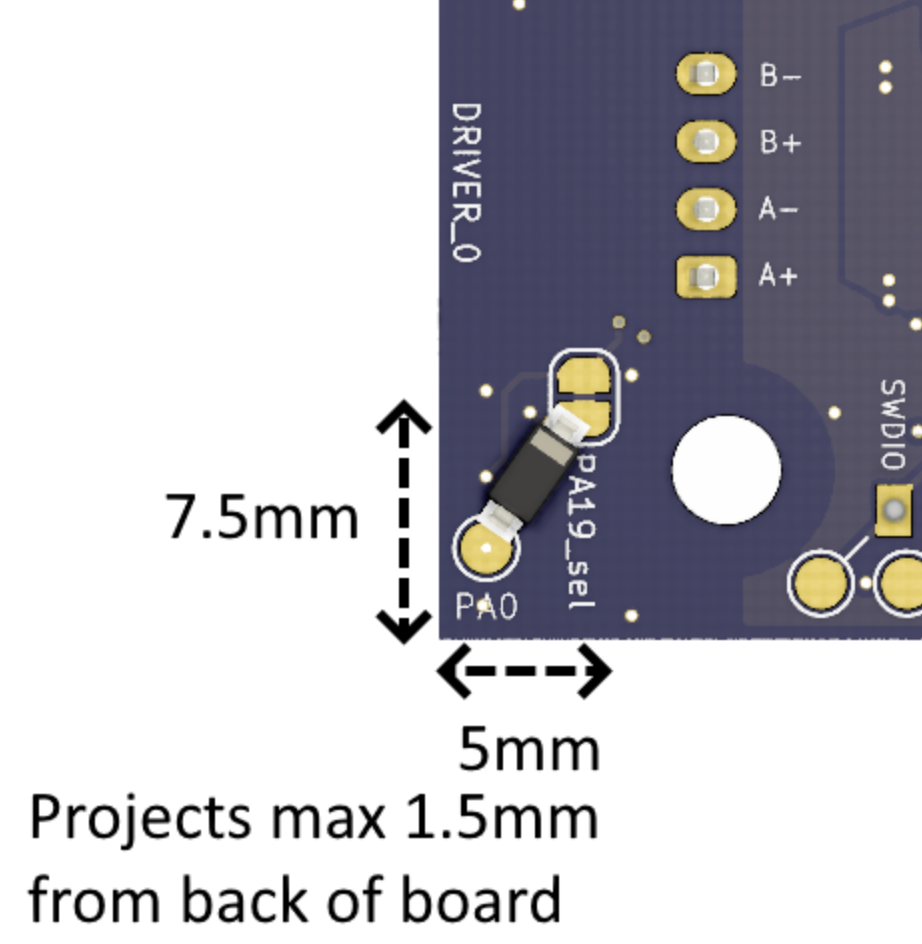
(source: 'Revision v1.1' tab here https://docs.duet3d.com/Duet3D_hardware/Duet_3_family/Duet_3_Toolboard_1LC#dimensions)Ian
Bed-slinger - Mini5+ WiFi/1LC | RRP Fisher v1 - D2 WiFi | Polargraph - D2 WiFi | TronXY X5S - 6HC/Roto | CNC router - 6HC | Tractus3D T1250 - D2 Eth
-
@droftarts said in 1LC TOOLBOARD v1.1. Accelerometer fail:
1N4148W
Thanks for the information, I will buy the diode and solder it, I hope this will solve the problem.