Cast Toolplate Bed Progress ?
-
@deckingman @droftarts @fcwilt
Quite annoyed with my bed, take a look;
I've tried everything, even dismantling it and only having the bed mounted to the bed frame omitting the the safety sheet, loosening all the fixing points.
Checked all my measurements for the i don't know how many times now.
This toolplate when it arrived did have some machine marks (scratches along one edge, )from the seller and offered a discount of 18%.
I wish I'd told them Send a new one.Dizzwold.
-
@Dizzwold Why do you suspect the tooling plate is the culprit? Have you checked that your XY gantry is tram? It looks to me like it's low in the back left corner. This might help https://www.youtube.com/watch?v=XLLdK7Bu464. The important part is from about 4 minutes and 20 seconds.
-
@deckingman @droftarts @fcwilt
Merry Christmas Guys.
Thank you for the link to your video explain the tram scenario. This may play some part in this and I'll have to investigate further.
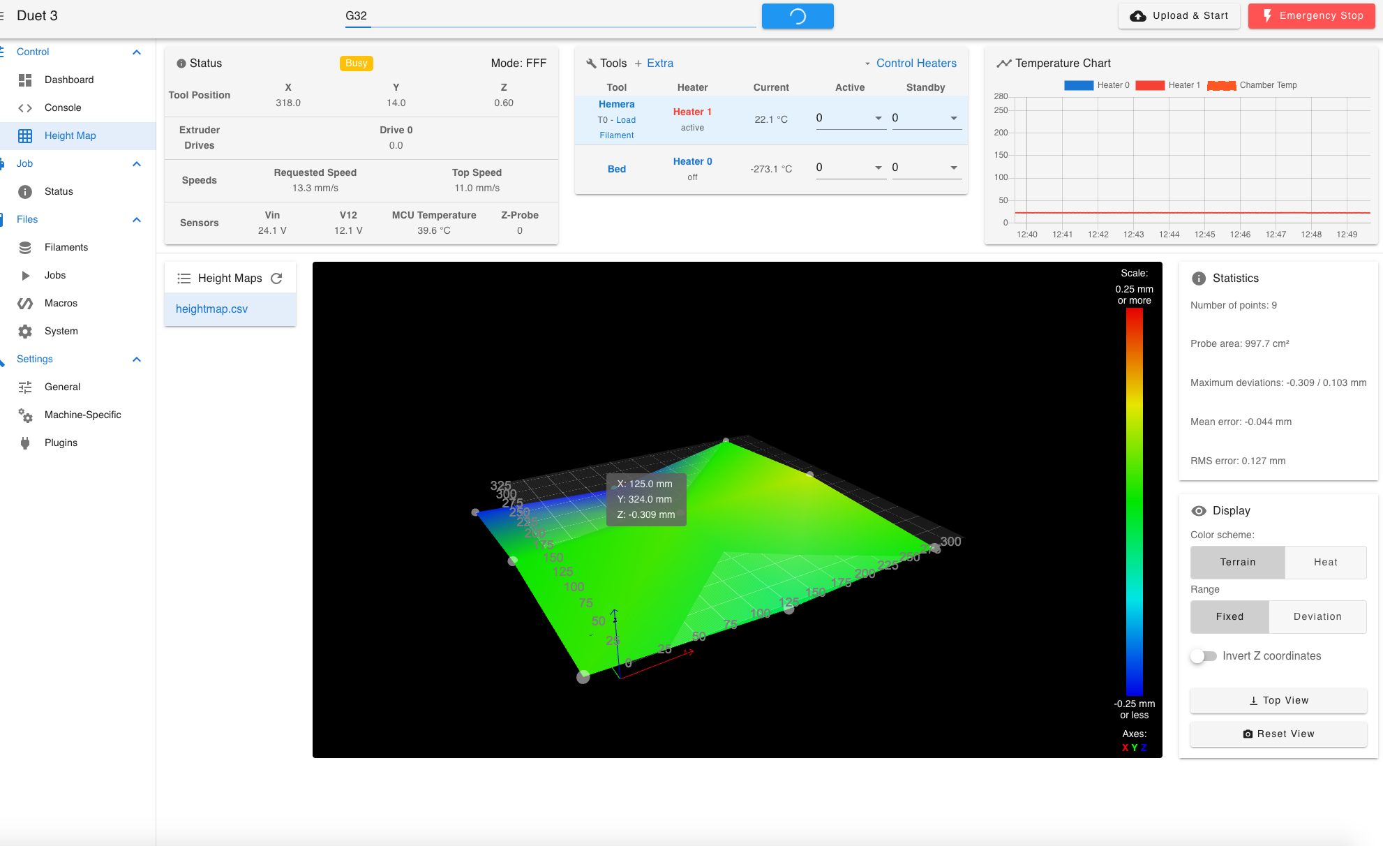
What isn't shown in the image above is the point measured at the back Left. The point at the back Centre is Z-0.309 where at the back Left was -0.264. I'm not ruling out a tram issue, but if it was, the back Left would have been a greater negative number than the back Centre?
I do actually have some old imperial dial clock somewhere in the garage that belonged to my father, but I've never made a bracket for them.
I might try and use my previous Bed Levelling macro (which took measurements from the four corners). The frame is still basically the original Tronxy X5SA Pro. The original bed had 6 adjusting screws, then mounted on 2 leadscrews. So Maybe I can use this instead of a dial using the BL Touch.
As my funds are limited I'm also still using the original Tronxy Rails (U grove bearing/rails), which would mean if it is a tram issue I'd need to shim the underside of the rails as these aren't blind joints and screwed down onto the end of a frame corner upright.
Dizzwold.
-
@Dizzwold You appear to have a kinematic bed, are the three steppers driven from separate drivers? If so, have you set up your bed.g? See https://docs.duet3d.com/en/User_manual/Connecting_hardware/Z_probe_auto_levelling
I also think you need a much finer bed mesh; you're only checking at 9 points.
Ian
Bed-slinger - Mini5+ WiFi/1LC | RRP Fisher v1 - D2 WiFi | Polargraph - D2 WiFi | TronXY X5S - 6HC/Roto | CNC router - 6HC | Tractus3D T1250 - D2 Eth
-
@Dizzwold Will your funds stretch to buying a decent straight edge? Search for "Plasterers Feather Edge". With a strong light behind it, you'll be able to see if the plate is flat or not. But I'd be willing to bet that it's a tramming issue. Ultimately you need to be sure that a plane described to the 3 lead screw attachment points is parallel with a plane described by the XY gantry with errors less than 0.1mm (I got mine to within 0.03mm).
As I said at the end of that video, you can either spend the time and do that, or you can use mesh compensation. But if you do the latter, there is no point in spending the money on expensive tooling plate which is guaranteed flat. (and if you use a continuous belt driving all 3 screws, you'll only have to level the bed once and never again).
-
Hi Ian, and Ian,
There are 3 Z axis motors and all on separate drivers and correct order from M584 drive mapping (Z1 Centre Left, Z2 Front Right, Z3 Rear Right)
So far my testing has been with everything running cold (cold nozzle and cold bed). I started with a 12 x12 bed mesh which initially highlighted the issue, so went to a 3 x 3 for quick tinkering and test.
I'm wondering if it's the bed not completely parallel to the bed frame?
@deckingman said in Cast Toolplate Bed Progress ?:
s I said at the end of that video, you can either spend the time and do that, or you can use mesh compensation. But if you do the latter, there is no point in spending the money on expensive tooling plate which is guaranteed flat
I agree. After using the bed that came with the printer, a bed fastened to a frame with 6 (3 front and 3 rear) adjusting screws, pulling it all over the place, then mounted to 2 leadscrews. This was the idea to invest in a decent bed where once I know it's set correctly, I pretty-much forget about it. More so the stress and strains of the old bed.
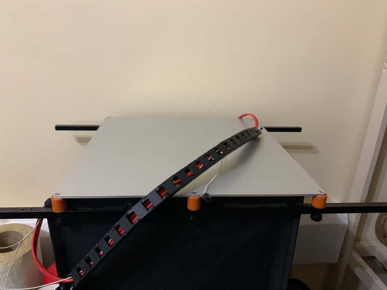
Here's the old bed for reference
-
Hi Ian and Ian,
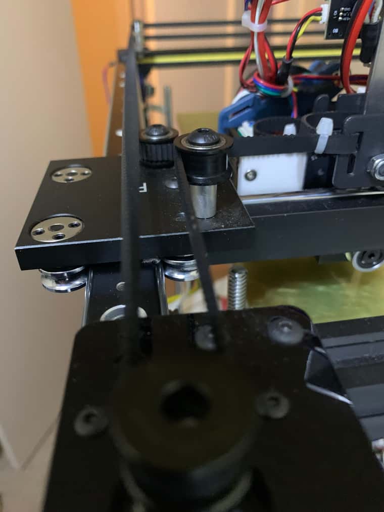
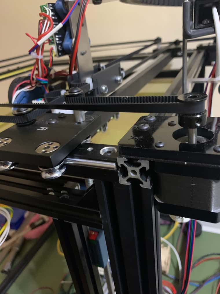
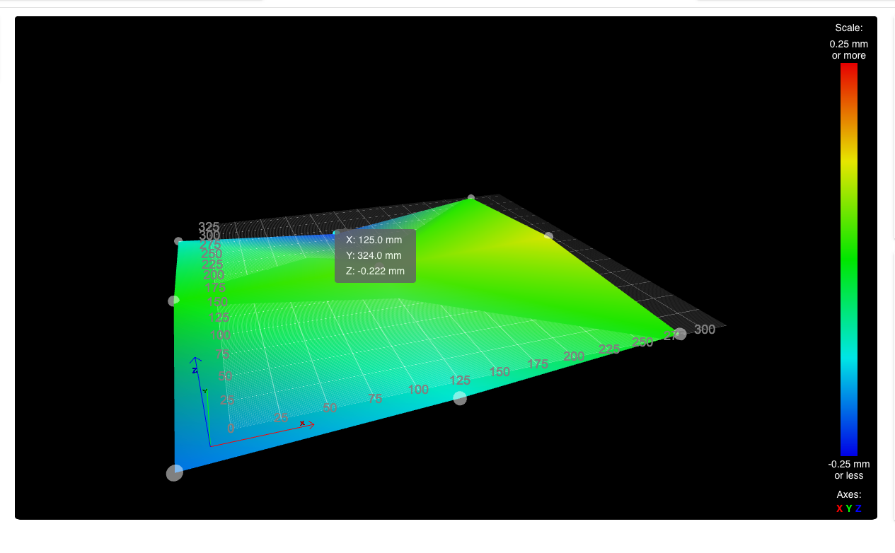
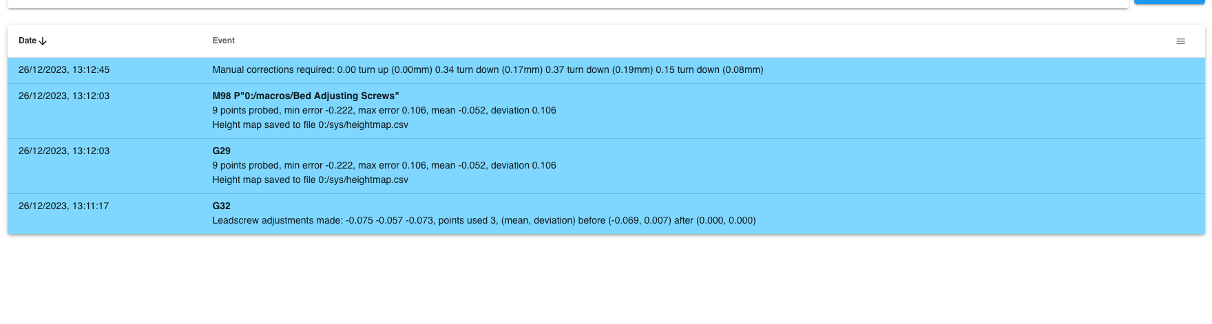
I've ran the 3 x 3 mesh and took the following images;
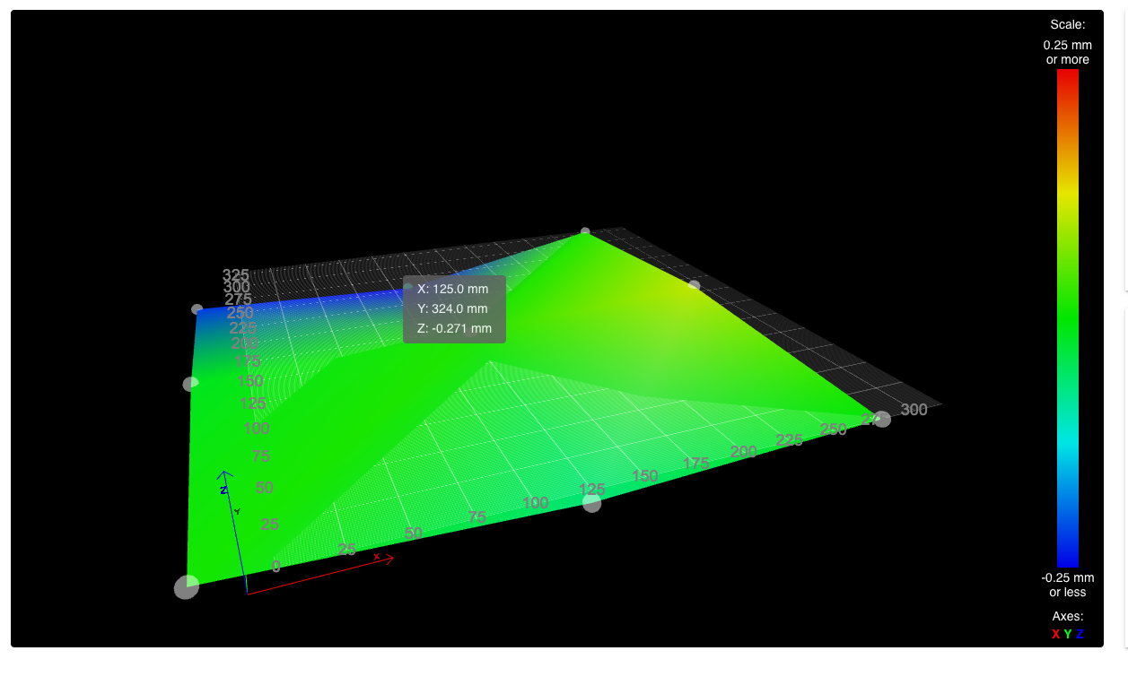
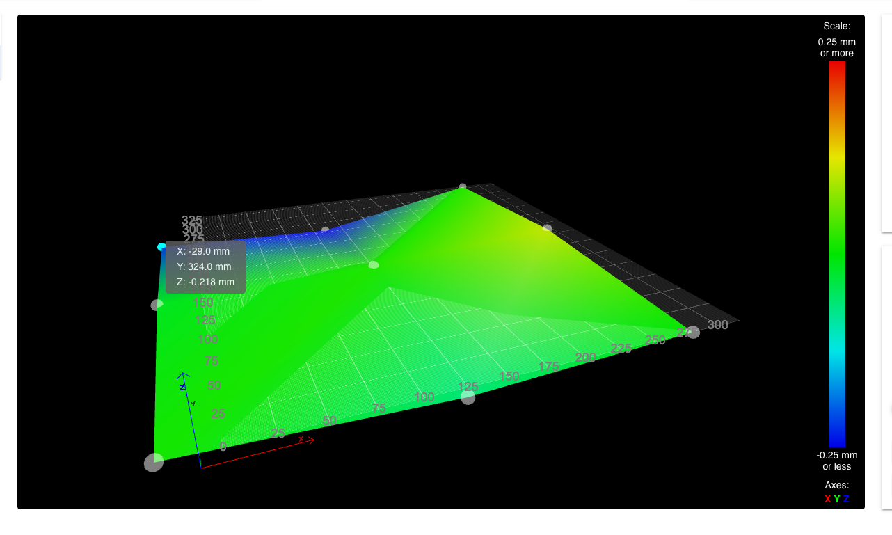
I've then ran my old Bed adjustment screws Macro which basically take a measurement from each corner;
Front Left, Front Right, Rear Right and finally Rear Left;G28 M671 X5:278:278:5 Y5:5:302:302 P0.5 G30 P0 X-29 Y1 Z-9999 ; probe front left G30 P1 X279 Y1 Z-9999 ; probe front right G30 P2 X279 Y324 Z-9999 ; probe rear right G30 P3 X-29 Y324 Z-9999 S4 ;probe rear left G1 Y0 F12000 G1 X0 Y0 F12000I then got the following measurements in Console, which would suggest that the bed isn't fully parallel to the bed frame more so in the Rear Left.
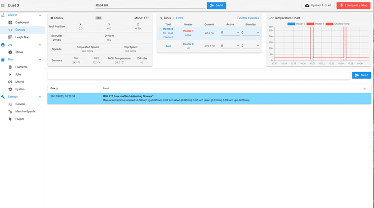
I can only assume this is due to a slightly shorter screw or a slightly deeper mounting hole in the bed.
Dizzwold.
-
With the washers and shims I currently have (1mm & 0.5mm), I think this is the best I'm going to get it.
Just ordered some 0.1 and 0.2mm shims, so can hopefully improve this in the new year 'while saving for a new frame'.
Dizzwold.
-
@Dizzwold definitely carry on with getting your frame and gantry trammel up, but be aware of the published specs (if any) for your cast plate.
As an example, this material and vendor is popular in the states:
https://www.midweststeelsupply.com/store/ATP5Flyer.pdfNote that for material less than 12.7mm thick, the flatness tolerance is .381mm or better across the entire plate. Example image of what ‘flatness’ means below.
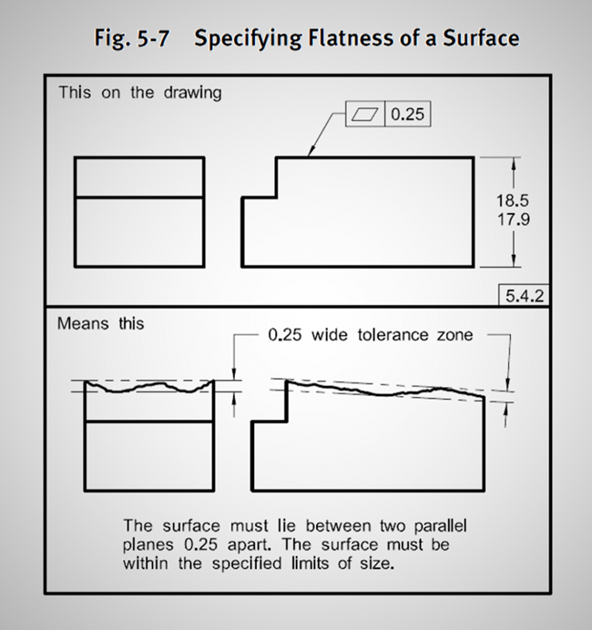
https://media.faro.com/-/media/Project/FARO/FARO/FARO/Images/Resources/2021/01/15/23/03/flatness-ASMEex-969x1030.png?h=692&w=650&rev=97ef025583f14db4a5c22b058fb7b809&hash=F3D4FD2D475501E30BEB379E0BBDA981Specs vary by manufacturer, and you may well never see the worse case flatness tolerance, but just a tidbit to keep in mind.
-
@sebkritikel said in Cast Toolplate Bed Progress ?:
.................... Note that for material less than 12.7mm thick, the flatness tolerance is .381mm or better across the entire plate.................
That's not exactly correct. The specs refer to "guaranteed flatness" not "flatness tolerance". It's a common safety margin that suppliers use to cover themselves in case of litigation. The quoted flatness also applies to the entire sheet which could have a length of 3670mm and a width of 1842mm. That's an area of 6.76 m^2 whereas if the OPs bed was 500mm x 500mm that would only be 0.25 m^2 so it's highly unlikely that his small section of a (machined) sheet would have a deviation anything like that.
-
@deckingman @droftarts @fcwilt @sebkritikel
Hi Guys,
I'm back with an update after much tinkering, finessing and frustration.
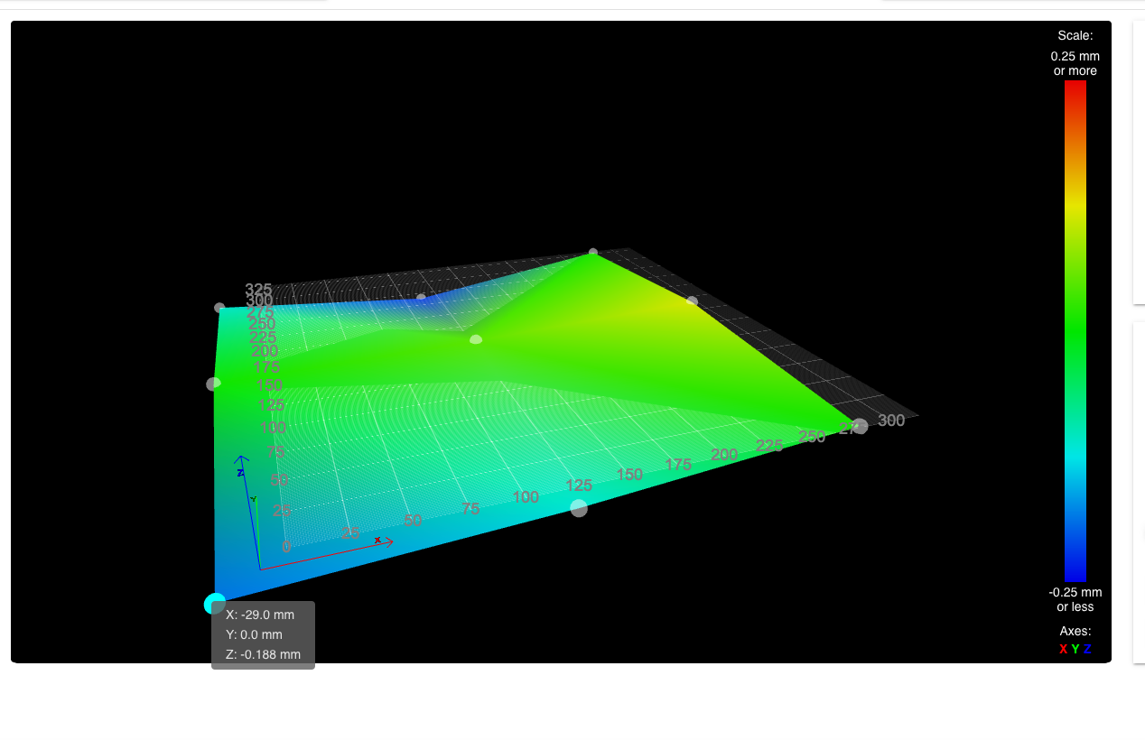
The following image show's a cold 9 point bed compensation. Again I've only used 9 points for quickness to test the flatness of the bed and to try and eliminate any tramming.
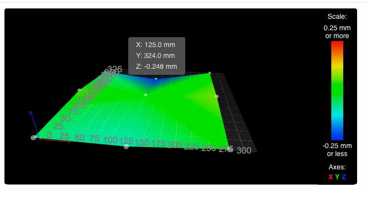
The point at the rear centre is now the only point that is out. The rest vary from +0.004 to -0.090.
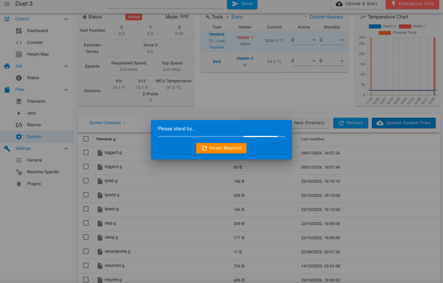
Going back to the Emergency stop button I have (the mushroom type on a NC circuit).
Is it possible so when the switch is reset, it will reset the Emergency Stop in DWC?
I've tried using M999 in a variety of ways, in config.g as trigger 0 and in sys/trigger2.g and just can't figure this out.
Config.g; Custom settings are not defined ; Emergency Stop M950 J2 C"!io3.in" M581 P2 T2 S0 R0 ;M582 T0 S0 ; Z Axis Limit Switch M950 J3 C"io2.in" M581 P3 T3 S0 R0 ;M582 T2 S0Trigger 2.g
;Trigger2.g Emergency Stop Button

M112				;stop all
M582 T2 S0
M999				;restart all
Trigger 3.g
;Trigger3.g Z Axis Limt Switch
M112				;stop all
M582 T3 S0
M999				;restart all
The Z Axis limit switch is a fail-safe for while I'm tinkering as I've already accidentally touched the paneldue after a M564 S0 and crashed the leadscrew nuts into the motor mounts.
Dizzwold.
-
@Dizzwold said in Cast Toolplate Bed Progress ?:
Is it possible so when the switch is reset, it will reset the Emergency Stop in DWC?
I've tried using M999 in a variety of ways, in config.g as trigger 0 and in sys/trigger2.g and just can't figure this out.
Config.gI'm not sure that you can use M999 to reset after an emergency stop. The docs say it'll restart the firmware after a software reset which isn't the same thing. The usual way to reset an emergency stop is to power cycle the board. I have mine wired such that it kills all power to the boards so resetting the emergency stop button effectively does just that. You could maybe do M98 P "config.g" which will run config.g again - that might work as a reset mechanism.
The way to do it would be to have two triggers, one that works on an active to inactive edge, and the other that works on inactive to active. So you can use M581 P2 T0 S0 R0 which will do an emergency stop as if M112 was run - you don't need create a trigger0 macro to do an emergency stop. Then use M581 P2 T2 S1 R0 to run the macro "trigger2" which would contain M98 P "config.g". You might need to swap S0 and S1 around depending on how the switch is wired.
-
Hi Ian,
@deckingman said in Cast Toolplate Bed Progress ?:
You could maybe do M98 P "config.g"
Now there's an idea, thank you for that.
-
Hi Ian,
A quick question. Should the
M582line be within thetrigger.gor within the mainconfig.g?Dizzwold.
-
@Dizzwold said in Cast Toolplate Bed Progress ?:
Hi Ian,
A quick question. Should the
M582line be within thetrigger.gor within the mainconfig.g?Dizzwold.
Not sure I understand. Triggers are activated when the input defined in M581 changes state. So you don't normally have to do anything as the relevant macro will run "automatically" when the input state changes. AFAIK, M582 is just a way of checking the state of the inputs so I've never used it.
-
Hi Ian,
Sadly the Trigger 2,
M98 P"config.g"has no influance on restarting DWC. It still needs manually resetting.
Config.g; Custom settings are not defined ; Emergency Stop M950 J2 C"io3.in" M581 P2 T0 S1 R0 ;M582 T2 S0 M581 P2 T2 S0 R0Trigger2.g
;Trigger2.g Reset Emergency Stop Button

M98 P"config.g"
I've tried many variants with
M112, M999, M400and tried changing theS0, S1, S-1values, although I have it connected on a NC circuit soS1on a non-inverted pin triggersT0(M112 Emergency Stop), then releasing the
Emergency Stop ButtonS0Triggers the same non-inverted pinT2, M98 P"config.g"
Have got something wrong somewhere? -
@Dizzwold Dunno. I guess we need to first check that the correct macro is being triggered with the switch in each position. Try doing M581 P2 T3 S1 R0 and keep the existing M581 P2 T2 S0 R0. So we have two triggers (2 and 3) and one should run on a rising edge the other on a falling edge. Then make trigger2.g with just a single command M118 S" This is trigger 2", and trigger3.g with just a single command M118 S"This is trigger 3".
Then exercise your switch and see what happens. Hopefully you'll get a message "This is trigger 2" when the switch changes from one state to another and "This is trigger 3" when the state changes back. Once we are sure that part is working, then we can think about what commands to put in each trigger macro.
-
@deckingman said in Cast Toolplate Bed Progress ?:
This is trigger 2
Hi Ian,
Hmm... I tried what you suggested above, and i worked as expected;
Trigger 2 when the E Stop Button is pressedS1
Trigger 3 when releasedS0So I've then replaced Trigger 2 with
M112
M999
and Trigger 3 with
M98 P"config.g"Same problem DWC on my computer needs a physical click on the RESET button displayed on the screen (paneldue states HALTED), so it would seem that the
M98 P"config.g"is the issue.
Config.g;; Custom settings are not defined ; Emergency Stop M950 J2 C"io3.in" M581 P2 T2 S1 R0 ;M950 J2 C"io3.in" M581 P2 T3 S0 R0 ; Z Axis Limit Switch ;M950 J3 C"io2.in" ;M581 P3 T3 S0 R0Trigger2.g;
;Trigger2.g Reset Emergency Stop Button
M112
M999

;M118 S"This is Trigger 2"
Trigger3.g
;Trigger3.g Z Axis Limt Switch

;M118 S"This is Trigger 3"
M98 P"config.g"
Maybe it's not possible?
Dizzwold
-
@Dizzwold said in Cast Toolplate Bed Progress ?:
Maybe it's not possible?
Maybe. I'd have thought there ought to be a way to recover from an emergency stop but the docs just talk about power cycling the board. I'm surprised running config g doesn't work because that is effectively all that happens when power is restored.......but there is possibly a work around.
The obvious one is do as I do and use the emergency stop button to physically interrupt the 24V power to the board(s).
But failing that, maybe we can do something else. So rather than an emergency stop, think about what you actually want to stop. I guess that's motors and heaters. Heaters are easy - just set the temperatures to zero in one macro and restore them in the other. So what about using M18 instead of M112 to disable motors? It might not be immediate though so might have to wait for any moves to finish which I guess is not what you want an emergency stop to do? M0 is another option but again, I don't think it will work until the current move is complete.
-
@Dizzwold said in Cast Toolplate Bed Progress ?:
Maybe it's not possible?
A question for @chrishamm I think.