tuning LW-PLA
-
Am I assuming correctly, that this LW-PLA is meant to foam up while extruded?
That would explain why the long retraction is necessary. It not only oozes out of the nozzle, but also expands.
But it only expands once and after a retract/unretract you miss some material.
So I guess you're on the right path.
Our regular PLA settings won't work here.What does the manufacturer say about settings? They must have testet this stuff before selling it.
-
@o_lampe said in tuning LW-PLA:
Am I assuming correctly, that this LW-PLA is meant to foam up while extruded?
That would explain why the long retraction is necessary. It not only oozes out of the nozzle, but also expands.
But it only expands once and after a retract/unretract you miss some material.
So I guess you're on the right path.
Our regular PLA settings won't work here.What does the manufacturer say about settings? They must have testet this stuff before selling it.
Yes and no, There are two types of foaming PLA.
from the manufacturers website;
FAQ
What is the difference between active foaming and passive foaming?PolyLite
 LW-PLA is not an active foaming filament, which means it will not foam when extruded from the nozzle depending on the temperature. PolyLite LW-PLA is already pre-foamed.
What are the pros and cons between active and passive foaming?
Active foaming:
You need to heavily modify your printing settings depending on the temperature and setup to compensate the foaming expansion of the material when printing.
You need to print at very high temperature to achieve light weight results (~250_), these high temperatures will create a lot of defects on the print such as stringing and blobs.
At very high temperature, active foaming can achieve lighter print than passive foaming however the print may suffer of serious stringing defects.Passive foaming:
You do not need to change any settings from your regular PLA settings (slight increase retraction) as PolyLite LW-PLA will offer light weight results even when printing at very low temperature (~190_C).
The lower the temperature the higher quality the print. -
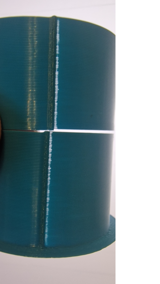
Unfortunately those settings seem to have some undesirable effects;
Left is ;
M566 E3000
M203 E6000
M201 E2000Right is;
M566 E150
M203 E2000
M201 E200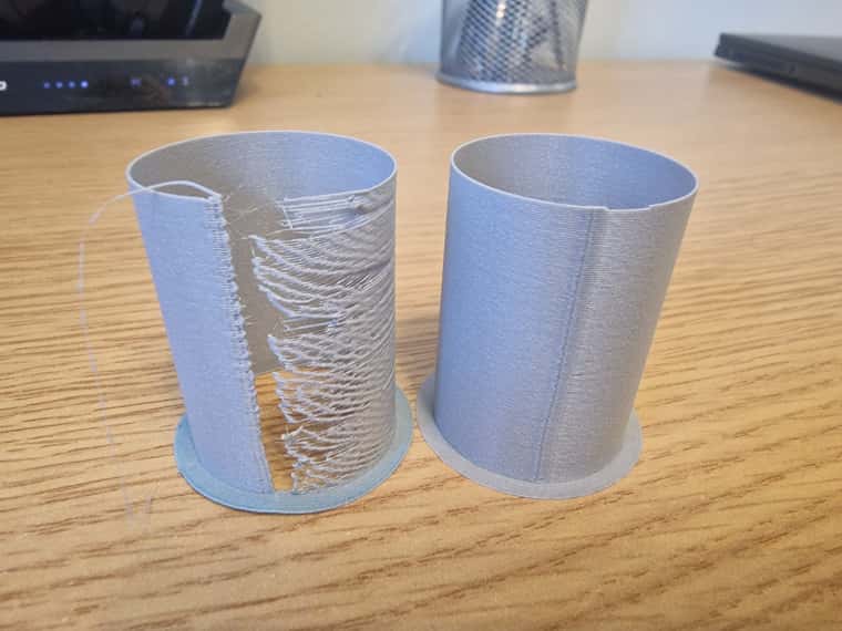
-
what were the rest of the settings from that test? PA, retraction, etc?
-
I've decided to start from scratch. It's been some time since I've printed anything, so I think a combination of firmware, and slicer updates have broken something.
I've reinstalled a fresh copy of prusa slicer, configured a generic printer, with the generic pla profile, with my original start and end gcode. The only thing I changed was retraction from 2mm to 0.4mm.
;Start
M104 S[first_layer_temperature] ; set extruder temp
M140 S[first_layer_bed_temperature] ; set bed temp
M109 S[first_layer_temperature] ; wait for extruder temp
M190 S[first_layer_bed_temperature] ; wait for bed temp
M557 X{first_layer_print_min[0]}:{first_layer_print_max[0]} Y{first_layer_print_min[1]}:{first_layer_print_max[1]} S20 ; define probe area
M98 P"bed.g" ; perform bed leveling
G92 E0 ; reset extruder

;End
G91 ; Switch to relative mode for the rest of end.g
G1 F2000 Z5 ; move bed down
G28 XY ; move head to home on XY
M104 S0 ; turn off extruder,
M140 S0 ; turn off bed,
M84 ; disable motors
M107 ; turn off part cooling fan
M81 S1 ; shutdown after all thermostatic fans have turned off
I'm also using standard pla now.
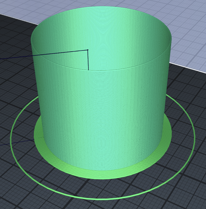
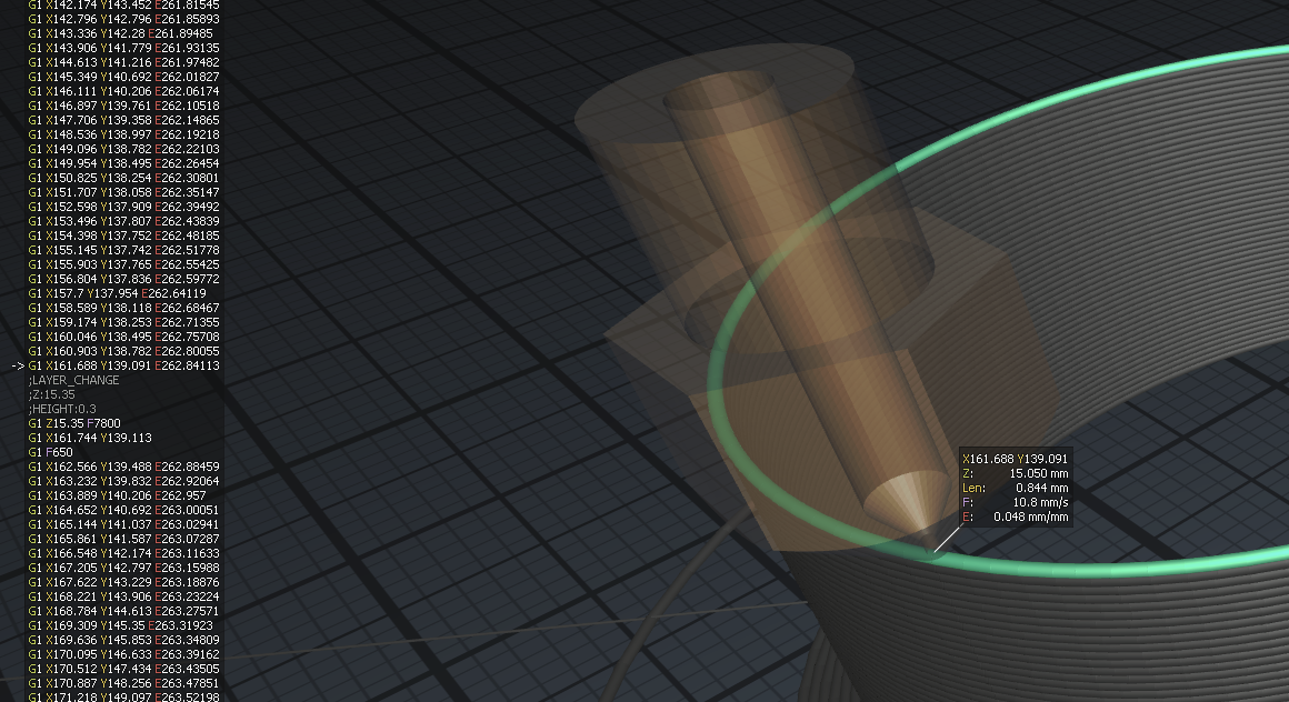
This is how a single wall cylinder prints;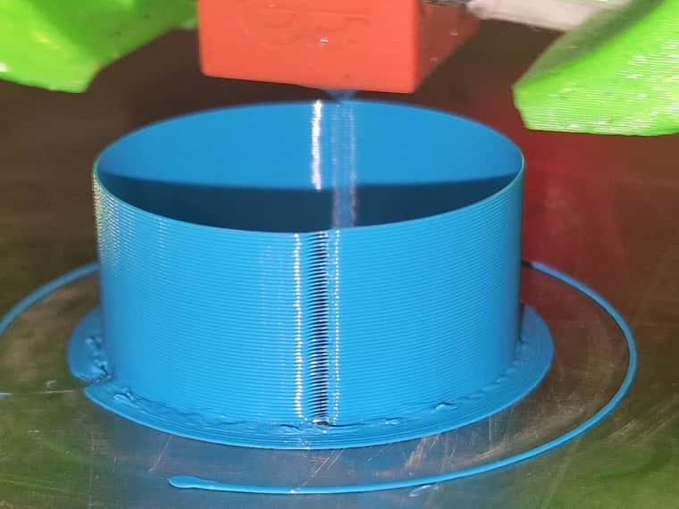
-
@nick9one1 could you upload that exact print file (gcode)? Thanks!
-
@sebkritikel sure, here you go.
-
@nick9one1 Thanks! File looks good - no tricks with coasting, no retraction etc.
Off topic perhaps, but why do you have interpolation disabled on the extruder?
M350 E16 I0 ; configure microstepping with interpolationHere is something quick I would do to start troubleshooting the extruder (specifically that gap). For now, I think keep pressure advance at 0
- Do a print, changing the extruder max speed to M203 E6000. Check if there are any changes.
- If there are NO changes to the print quality, keep the max speed at M203 E6000. Change acceleration from M201 E200 to M201 E3000. I'm going to guess you'll see a physical change to the print once you change the extruder acceleration.
- Depending on how things are looking, try extruder jerk at M566 E3000 again.
I think we want to eliminate that gap (partly), adjusting extruder jerk/accel, then play around again with PA.
I have some python post-processing scripts that can simultaneously tune things like pressure advance + jerk, etc. Can share them later.
-
Thanks, Things are looking a little better...
I found a config.g for my printer here https://github.com/FYSETC/FYSETC-BLV-MGN-CUBE/blob/main/Firmware/config3.x/sys/config.g although I think that version uses a V6 clone.
After updating my config.g with those settings my print is looking a little better.
config.gThis is printed with the above config.
The first 10 layers are normal, after later 10 I sent M203 E6000 in the console while it was printing. Then after another 10 I sent M201 E3000, then after another 10 I sent M566 E3000.I can't really see any discernible change in the print.
this is the cylinder gcode. Shape-Cylinder (1).gcode
-
I also came across this that may help. This is my exact printer and extruder (although volcano), with settings for klipper.
https://www.blvprojects.com/post/klipper-ultra-fast-printing-9000acc-500mm-s
-
@nick9one1 Cool! So looking at the new config.g, I see a few changes.
- M566 changes, jerk was reduced for X, Y, Z, and increased slightly for E. I would go back and increase the Z jerk, as a low Z jerk can cause issues with X-Y travel moves (stuttering) if you use mesh bed compensation.
- Max speeds were reduced for X and Y, increased for Z
- Acceleration was reduced for X, Y, and Z, increased for E
I've found that with higher acceleration values for X and Y, I have to change pressure advance settings. Based on your before/after print after your new config.g, I think the reduction in X and Y acceleration has 'improved' the seam.
My suggested config.g changes:
M566 X600.00 Y600.00 Z150.00 E3000.00              ; set maximum instantaneous speed changes (mm/min) - increased Z and E
M203 X20000.00 Y20000.00 Z2000.00 E6000.00       ; set maximum speeds (mm/min) - increased E
I would also see if you're happy with the Z acceleration value (your new 100 vs old 200. probably too small to notice or care).
I think once you make the above changes, you can then start tweaking pressure advance settings. Here is the same print file from above, but I varied PA from (Starting with whatever your default is for the first 10% of the file) .001 to .35.
pa-shape-cylinder.gcodeYou can try out the file python file here, change your file name/location as needed.PS pa.py
import re min_pressure_advance = 0.001 # set minimum pressure advance max_pressure_advance = 0.35 # set maximum pressure advance no_tune_pct = 10 # set the percentage of layers to not tune input_filename = r"C:\Users\Jared\Downloads\1704556218097-shape-cylinder.gcode" output_filename = r"C:\Users\Jared\Desktop\pa_1704556218097-shape-cylinder.gcode" # read the input file with open(input_filename, 'r') as f: in_gcode = f.readlines() max_print_height = 0 for line in in_gcode: match = re.match(r';Z:(\d+(\.\d+)?)', line) if match: current_height = float(match.group(1)) max_print_height = max(max_print_height, current_height) # calculate the pressure advance range and increment pressure_advance_range = max_pressure_advance - min_pressure_advance pressure_advance_increment = pressure_advance_range / (max_print_height - max_print_height * no_tune_pct / 100) # iterate through the input file and modify pressure advance as needed out_gcode = [] current_print_height = 0 for line_num, line in enumerate(in_gcode): # check if this is a Z comment indicating the current layer height if line.startswith(';Z:'): current_print_height = float(line.split(':')[1]) # check if we should tune this layer based on print height if current_print_height > max_print_height * no_tune_pct / 100: # calculate the pressure advance for this layer based on print height pressure_advance = min_pressure_advance + (current_print_height - max_print_height * no_tune_pct / 100) * pressure_advance_increment # replace the Z comment with a modified one that includes the pressure advance command out_gcode.append(f";Z:{current_print_height:.3f}\nM572 D0 S{pressure_advance:.3f}\nM572\n") else: out_gcode.append(line) else: out_gcode.append(line) # write the modified file to disk with open(output_filename, 'w') as f: f.writelines(out_gcode) -
Thanks again. I';ve made the changes you suggested.
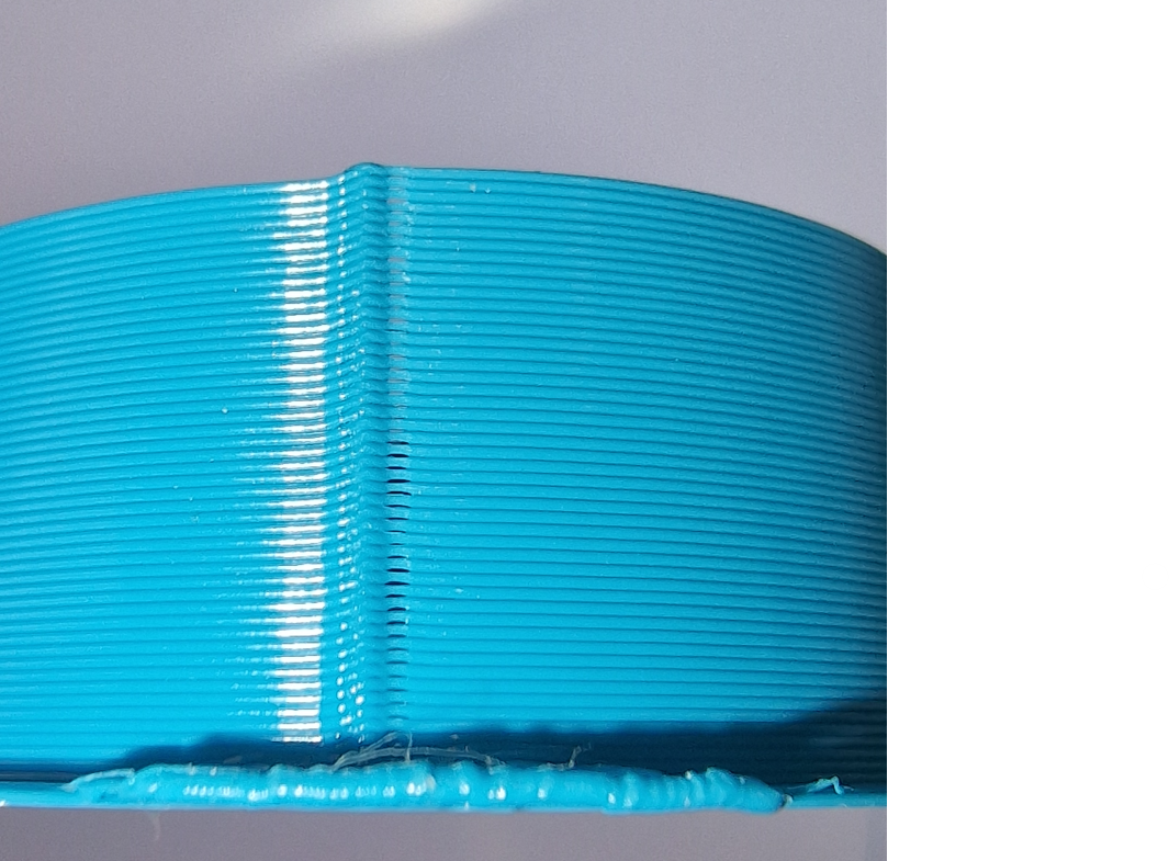
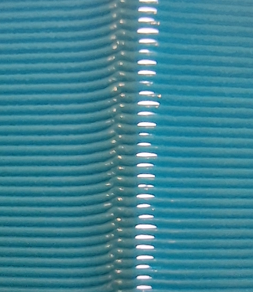
I'm still seeing small gaps after de-retraction, It's not quite so obvious without a light source behind the image;
I did a test here; the top trint is with your latest suggestions. And the the descond print has 0.5mm extra length on deretraction. That's quite a lot, but visually I can barely tell any difference.
Another image even closer, seems to show the layer change looking ok. The gaps happen after the de-retraction and when it starts to print the new layer?
-
@nick9one1 Stupid question, but did you check the grubscrew of the extruder shaft? A loose screw would explain the bulge and gap.
-
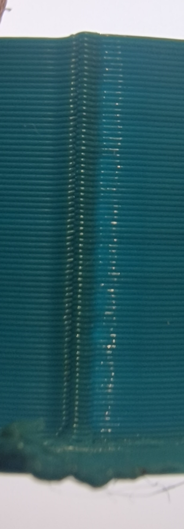
@o_lampe not a stupid question at all!
The grub screw felt tight as I couldnt rotate the heat block at all. But I stripped and reassembled anyway..Voilà, the same part as above (the white bits are just refections)
I'll continue with @sebkritikel's pressure advance tuning next.
-
@nick9one1 said in tuning LW-PLA:
I did a test here; the top trint is with your latest suggestions. And the the descond print has 0.5mm extra length on deretraction. That's quite a lot, but visually I can barely tell any difference.
other image even closer, seems to show the layer change looking ok. The gaps happen after the de-retraction and when it starts to print the new layer?Important to note!!! Your cylinder print does not have any retractions or de-retractions! I would not add a slicer-generated extra length move at this time (or at all honestly. wait until PA and stuff is 100% tuned).
Notice there are not any retract moves in the image and gcode snipped above. -
Can you make a video of it in action?
-
thanks @sebkritikel I hadn't considered there was no retraction on layer change. It makes sense now that I can't see any difference with the +0.5 after retract.
@Phaedrux
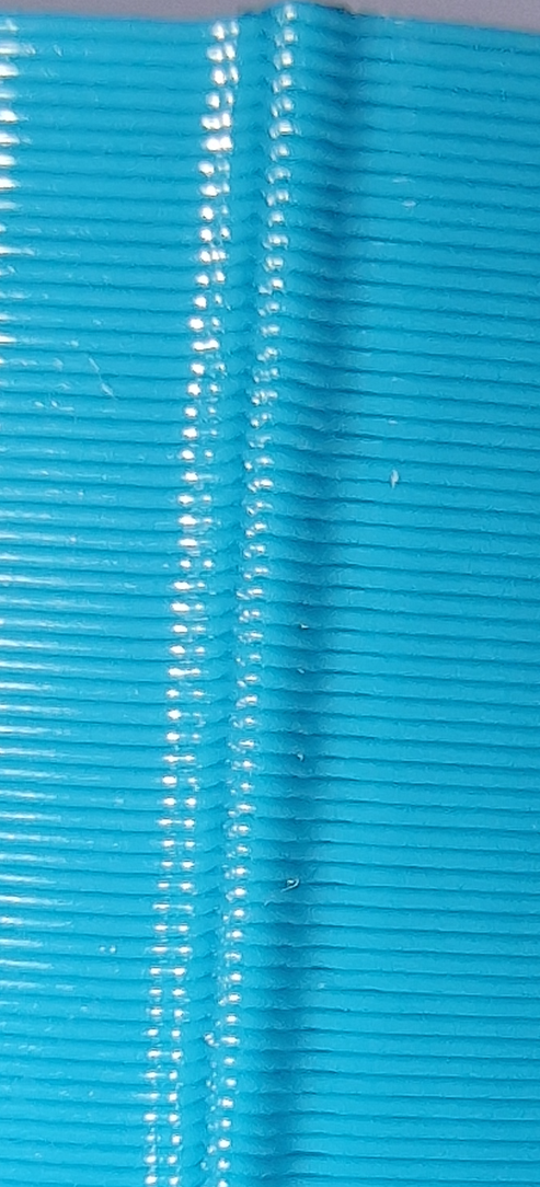
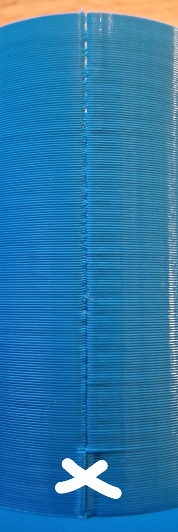
I think the main issue is resolved now. It was some sort of mechanical issue that has disappeared after I stripped and rebuilt the hot end. I no longer get the gaps at the start of a new layer.@sebkritikel thank you for providing the PA cylinder test. I've since re-tuned the flow, temp and retraction so used some after layer change code in prusaslicer,
; 0.2mm layer, 8 bands 5mm each, total height 40mm
{if layer_num== 1}M572 D0 S0.4
{elsif layer_num== 25}M572 D0 S0.05
{elsif layer_num== 50}M572 D0 S0.06
{elsif layer_num== 75}M572 D0 S0.07
{elsif layer_num== 100}M572 D0 S0.08
{elsif layer_num== 125}M572 D0 S0.09
{elsif layer_num== 150}M572 D0 S0.10
{elsif layer_num== 175}M572 D0 S0.11
{endif}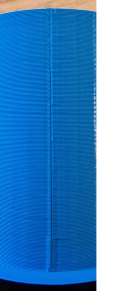
towards the top looks best, so I then printed another 0.12 - 0.18 (ignore the bottom band I mistakenly left it at 0.4)
-
@nick9one1 said in tuning LW-PLA:
The grub screw felt tight as I couldnt rotate the heat block at all
I meant the screw that tightens the filament roller to the gear-shaft. Any loose fit there would add bulge and gap at a layer seam.
But as was mentioned, you're printing in vase mode.
//edit OK, it's single wall, but no vase mode, so my above tip is still valid. -
Are you going to print airplane wings with this LW PLA? If yes, even and stable extrusion factor is important, I.e. you should look into vase mode. Recent Prusa Slicer has updated their vase mode to match the spiralize outer contour algorithm of Cura which should help with keeping extrusion more equal... and as always, printing slower will also help.