How to set M425 backlash compensation?
-
Can you confirm my understanding from this explanation?
If backlash is of 0.180, with default multiplier of 10, steps would be inserted to make up at least 1.8mm of distance.
If i keep multiplier as 15, then steps to compensate for upto 2.7mm of distance shall be inserted? -
@JayT I believe, that the extra steps required to compensate are spread out during the multiplier -length.
A multiplier of 10 would insert some extra steps every 10th regular step.
The lower the multiplier, the faster the compensation is done, but with the risk to overburden the stepper. Maybe a lower jerk setting is recommended?Just guessing, I'd never use that feature.
-
@o_lampe : If we want to avoid using backlash, how to solve this problem ?
When I used backlash value with default S factor, gaps in the circle reduced & shapes got better.
-
@JayT I would recommend keeping the 'S' factor at 10 (default value for now). but doing some testing at different values. Note the comment on possible skipped steps with too low of a value of 'S' (you will need to determine what too low is for your use case). Your M425 command would thus look like
M425 X0.18 Y0.18 S10From the Gcode docs... "The additional steps are inserted over a distance of at least the distance multiplier times the amount of backlash". In your case, .18mm * 10 = backlash of .18mm is taken up over 1.8mm. If your 'S' value was say, 5mm then .18mm * 5 = .18mm of backlash taken up over .9mm.
-
@sebkritikel : Ok understood. So If I increase the S value to say S50, the defect of gap will not get fixed, as backlash shall be compensated at a longer distance than needed. Right?
-
Thank you for clarity.
When I try the way you mentioned, gaps in prints have reduced. Specifically circles. But I had to use value "1" in S factor. With default S10, on printing circles, they went too straight. vertical & horizontal sides.
- this also reduced some gaps in printing other objects, specifically during infills.
I have couple of questions:
a) Are there any sideeffects of using this backlash option? How to check those?
(I tried printing XY calibration cube, it came out fine in dimensions.)b) Actual backlash for X axis that I measure is around 200 um using dial guage. But a value of 250 helped me to fix the problem in X direction. Any method to measure this quick or its trial & error based?
c) X & Y backlash value being different, can cause any defects in print shapes ?
d) Can I use value of 0.1 or 0.5 for S factor or minimum is 1? Because what I understood is the lower S value, the quicker it compensates backlash & shape distortion is least. So points where X & Y change their direction during print, can be smoother these extra steps are applied in the smallest distance possible, ofcourse without overloading stepperdriver too much.
-
@JayT Great questions! Going to tag @dc42 as backlash compensation is a newer feature (and I don't see it listed in the RRF change log!).
I have used a dial gauge and measured the backlash on my Y-axis, and measure about .15mm. With only a small amount of testing, it seems as if the compensation works well.
Intuitively I could see how a smaller value of "S" would improve more print segments, as 10*backlash=a fairly large value (relative to things like small diameter circles).
A) I would not use a 'calibration' cube to calibrate things like backlash or print size/scaling. I would only use a calibration cube as a quick check to ensure the printer is functioning at its lowest level (able to move, extrude, be at roughly the correct size, right height off build plate, etc). For true printer calibration, I highly recommend this video: https://www.youtube.com/watch?v=H7OsnMLDIMw I also highly recommend purchasing the model/spreadsheet, as it is really well done, and offers insight into extrusion, print shrinkage, and axis skew.
As part of that, I wonder if printing the model without backlash compensation, and then with backlash compensation, as merits. Something I could certainly test. As far as other methods of measuring backlash (you're using a dial gauge, which when used properly is probably the best method), here is an example on how an older professional style printer measured Y-axis backlash - a series of zig-zags, where the user inspects the print picking the most evenly spaced lines.
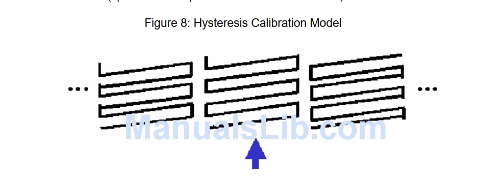
Something like this could work well:
https://www.thingiverse.com/thing:3060573C) Axes having uncorrected backlash of differing amounts will definitely produce print defects. I can't imagine correcting them will induce more/different defects, however since this is a newer (and somewhat unpublished feature) reporting testing and validation to the forums will be of value to the RRF dev team.
D) I think the recommended value of "S" is going to vary greatly printer to printer. I could see on other printers (say a printer with some sort of rack and pinion) with a much greater backlash value might need an "S" value closer to 10 (As the amount of backlash needed to be compensated for could cause motor issues on shorter segments), but I think on my printer (Y-axis with some belted gearing down) the .15mm could likely be taken up easily with very small values of "S". It would be interesting to test this by running something like a 'ringing tower' or some other test print, changing the "S" parameter with height (decreasing "S" as the height increases), and noting if there are any visible differences.
-
@sebkritikel said in How to set Blacklash ?:
I don't see it listed in the RRF change log
Here, under new features: https://github.com/Duet3D/RepRapFirmware/wiki/Changelog-RRF-3.x-Beta#reprapfirmware-350beta2
M425 backlash compensation is supported experimentally
Additionally, under Object Model changes:
Added float field move.axes[].backlash which is the configured backlash compensation for the corresponding motor in mm
Added integer field move.backlashFactor which is the configured M425 S parameterUnfortunately, I don't have much to add as to best practices on how to use it!
It appears that Marlin's backlash compensation is similar: https://marlinfw.org/docs/gcode/M425.html
Marlin also has a backlash calibration Gcode, but I think this could be done in RRF with a macro, using existing probing commands: https://marlinfw.org/docs/gcode/G425.htmlAs far as I can tell, Klipper doesn't have backlash compensation.
Ian
Bed-slinger - Mini5+ WiFi/1LC | RRP Fisher v1 - D2 WiFi | Polargraph - D2 WiFi | TronXY X5S - 6HC/Roto | CNC router - 6HC | Tractus3D T1250 - D2 Eth
-
Can you help in changing subject : correct the typo in spelling of Backlash in thread subject? (i.e. remove that extra 'l' for easy search appearance"
Thanks.
@sebkritikel : I have gone through the suggestions and will try that print for backlash.
One more question:
-e) Can steps/mm be also updated in addition to setting backlash.
I understand on direction change backlash will act to include few pulses to compensate for loss of move. However, steps/mm will also add up some pulse to stepper, to print the exact dimension.
The reason I ask is, the diameter of circle I print now has variance in diameter, when measured in Y direction as compared to Xdirection. & variance is 300-350um. So diameter in vertical direction is say 60mm then in X direction is say 59.7mm . Is this variance acceptable in fdm printing?So should I measure steps/mm & set them ?
-
@JayT said in How to set Blacklash ?:
Can you help in changing subject
Done. You can usually do this by editing the first post in the thread, but there is a time limit on editing posts for users.
Ian
-
@droftarts said in How to set M425 backlash compensation?:
@sebkritikel said in How to set Blacklash ?:
I don't see it listed in the RRF change log
Here, under new features: https://github.com/Duet3D/RepRapFirmware/wiki/Changelog-RRF-3.x-Beta#reprapfirmware-350beta2
 it is there! I must have fat fingered my search!
@JayT said in How to set M425 backlash compensation?:
@sebkritikel : I have gone through the suggestions and will try that print for backlash.
One more question:
-e) Can steps/mm be also updated in addition to setting backlash.
I understand on direction change backlash will act to include few pulses to compensate for loss of move. However, steps/mm will also add up some pulse to stepper, to print the exact dimension.
The reason I ask is, the diameter of circle I print now has variance in diameter, when measured in Y direction as compared to Xdirection. & variance is 300-350um. So diameter in vertical direction is say 60mm then in X direction is say 59.7mm . Is this variance acceptable in fdm printing?So should I measure steps/mm & set them ?
Tough one. I would firstly recommending printing that cali-‘flower’ I shared via the YouTube link, as it has 8+ measurement points and an associated spreadsheet that reports back various calibration values. I think it’s a really great baselining tool.
Changing the steps/mm could be of use, but I think it’s important to validate if the steps/mm truly needs to be changed, or if you have some other motion system issue. Is it always 300-350um on a print if any size, or is it always a % of the length? Questions that calibration video I linked can help you answer.
-
Before I proceed to measure steps/mm correction, Can you tell me in general how much the is the diameter variation in itself of a CIRCLE print of good quality ?
As in if the variation of circle is within 100-200um (somewhere diameter being 60, somewhere 59.9/59.8), then is it normal in belt system & guide rod systems? -
@JayT IMHO, the backlash question has been answered and we should keep the gap-discussion in your other thread.
-
@o_lampe :
Right. In that case you can resolve this thread.
Thanks. -
 undefined Phaedrux marked this topic as a question
-
undefined Phaedrux has marked this topic as solved
-
 undefined sinole referenced this topic