Duet3D Logo Duet3D
    • Tags
    • Documentation
    • Order
    • Register
    • Login

    Out of Sync for sync motors (same Axis)

    Scheduled Pinned Locked Moved
    General Discussion
    4
    25
    741
    Loading More Posts
    • Oldest to Newest
    • Newest to Oldest
    • Most Votes
    Reply
    • Reply as topic
    Log in to reply
    This topic has been deleted. Only users with topic management privileges can see it.
    • jay_s_ukundefined
      jay_s_uk @maor3degem.co.il
      last edited by

      @maor3degem-co-il best update the firmware and try again
      then if it happens again, grab an M122 output after the occurance

      Owns various duet boards and is the main wiki maintainer for the Teamgloomy LPC/STM32 port of RRF. Assume I'm running whatever the latest beta/stable build is

      maor3degem.co.ilundefined 2 Replies Last reply Reply Quote 0
      • maor3degem.co.ilundefined
        maor3degem.co.il @jay_s_uk
        last edited by

        @jay_s_uk
        thanks
        will do so and keep you posted

        1 Reply Last reply Reply Quote 1
        • maor3degem.co.ilundefined
          maor3degem.co.il @jay_s_uk
          last edited by

          @jay_s_uk
          Here is again, 3 pairs of motor are out of sync.
          config.g M122.txt Pic.jpg Vid.mp4

          this is with the latest FW version 3.5.2

          please advise

          Maestroundefined 1 Reply Last reply Reply Quote 0
          • Maestroundefined
            Maestro @maor3degem.co.il
            last edited by Maestro

            @maor3degem-co-il

            Any macros being called during the print? Anything running in daemon.g?

            In your first post's video the right-hand motor looks to be turning 16x faster than the left, so, that's no random number. Wonder if code is being called somewhere that is changing your microstepping or steps/mm?

            maor3degem.co.ilundefined 2 Replies Last reply Reply Quote 0
            • maor3degem.co.ilundefined
              maor3degem.co.il @Maestro
              last edited by

              @Maestro
              I alsothought this could be,
              but. this 2 motor define as the same axis. so cannot be done.
              and also I check the m350 and it remain OK as define in the config

              020205e4-82aa-4812-b485-0e63c39a489a-image.png

              droftartsundefined 1 Reply Last reply Reply Quote 0
              • droftartsundefined
                droftarts administrators @maor3degem.co.il
                last edited by droftarts

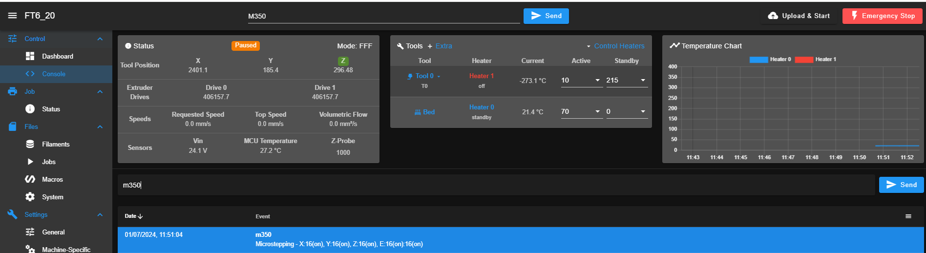
                @maor3degem-co-il Sorry you are having issues. I notice that the failing axes are usually plugged in to the DueX board. In your first crash it was Z that lost sync, when the following was defined:

                M584 X3 Y1:2 Z5:7:8:9 E4:0
                

                In the second, it looks like X lost sync, and dropped on the Z axis that knocked the bed out of level. Were the Z motors also turning at different speeds? The M584 was:

                M584 X5:6:7:8 Y3 Z2:1 E4:9
                

                As you have been using quite old firmware, and this has not been reported before, we do not think this is a firmware bug. Most likely is interference on the ribbon cable, that carries the SPI commands that set up the drivers, as well as controlling them. It could also be due to a poor earth wire between the Duet and Duex, causing ground issues on ribbon cable between the two boards.

                Please check the following:

                • Check there are no other wires running close to or across the ribbon cable between the Duet and Duex. Ribbon cables are quite susceptible to interference; wrapping them in foil can help, but better to remove any close source of interference.
                • Check that the DueX board is properly grounded. See https://docs.duet3d.com/Duet3D_hardware/Duet_2_family/DueX2_and_DueX5#power-wiring

                If that doesn't help, please take a picture and post it, showing how your Duet and DueX boards are wired.

                Ian

                Bed-slinger - Mini5+ WiFi/1LC | RRP Fisher v1 - D2 WiFi | Polargraph - D2 WiFi | TronXY X5S - 6HC/Roto | CNC router - 6HC | Tractus3D T1250 - D2 Eth

                maor3degem.co.ilundefined 1 Reply Last reply Reply Quote 0
                • maor3degem.co.ilundefined
                  maor3degem.co.il @droftarts
                  last edited by

                  @droftarts Hi
                  thanks for your help,
                  in the second, the Z motor also turning different length , the same symptom as with the X axis. and the Z connected to the main board...

                  in addition we face this problem with a few machines we have (5) and it is occur also in the main boards drivers.

                  please advice what else can help us to solve this problems

                  Regards
                  Maor

                  droftartsundefined maor3degem.co.ilundefined 3 Replies Last reply Reply Quote 0
                  • droftartsundefined
                    droftarts administrators @maor3degem.co.il
                    last edited by

                    @maor3degem-co-il said in Out of Sync for sync motors (same Axis):

                    in the second, the Z motor also turning different length , the same symptom as with the X axis. and the Z connected to the main board

                    It is possible interference on the SPI bus via the ribbon cable, or poor ground between the Duet and DueX, could affect the drivers on the main board as well. Please look at my previous message for advice. Please post a picture of the wiring if that doesn't help.

                    in addition we face this problem with a few machines we have (5) and it is occur also in the main boards drivers.

                    Maybe they are all wired the same way? What is different about these 5 machines compared to the other 15?

                    please advice what else can help us to solve this problems

                    At the moment, I don't have any other theory about what is wrong based on the information you have give, or I'd tell you.

                    Ian

                    Bed-slinger - Mini5+ WiFi/1LC | RRP Fisher v1 - D2 WiFi | Polargraph - D2 WiFi | TronXY X5S - 6HC/Roto | CNC router - 6HC | Tractus3D T1250 - D2 Eth

                    1 Reply Last reply Reply Quote 0
                    • maor3degem.co.ilundefined
                      maor3degem.co.il @maor3degem.co.il
                      last edited by

                      @maor3degem-co-il
                      we have 15 machine that look pretty much the same.
                      we used them for 4 years without any problem like this,
                      this start happen in the last 4 months...

                      can heavy dust cause this?

                      1 Reply Last reply Reply Quote 0
                      • droftartsundefined
                        droftarts administrators @maor3degem.co.il
                        last edited by

                        @maor3degem-co-il I also note on your last image there is an error on the PanelDue:
                        0e651313-a7cf-4b36-88a7-18e363c9968f-image.png

                        I think this says "Driver 3 error: Phase A short to ground phase B short to ground". Is that correct? Did the Y axis wires cut when the carriage fell?

                        can heavy dust cause this?

                        Do you mean on the Duet boards, or on the mechanical components? However, I don't think either would cause these kind of problems, because something is causing the configuration of the driver chip to change without the firmware knowing. Though it wouldn't hurt to use compressed air to clean off the boards, if there's a lot of dust on the boards. If there's dust in the mechanics, I'd expect skipped steps rather than a change in the driver configuration.

                        After 4 years, it's probably time to check/replace wiring, check contact especially in screw terminals, etc.

                        Ian

                        Bed-slinger - Mini5+ WiFi/1LC | RRP Fisher v1 - D2 WiFi | Polargraph - D2 WiFi | TronXY X5S - 6HC/Roto | CNC router - 6HC | Tractus3D T1250 - D2 Eth

                        maor3degem.co.ilundefined 1 Reply Last reply Reply Quote 0
                        • maor3degem.co.ilundefined
                          maor3degem.co.il @droftarts
                          last edited by

                          @droftarts
                          The driver error is due to the carriage fall cut the wire.

                          by the way, the machine is on pause right now and I can see the problem of the motors. if I will restart the machine the problem will go a way till next time.

                          and before restart the is no evidence of changing in the configuration

                          maor3degem.co.ilundefined 1 Reply Last reply Reply Quote 0
                          • maor3degem.co.ilundefined
                            maor3degem.co.il @Maestro
                            last edited by

                            @Maestro
                            I double checked it and
                            the motor doesn't move 1/16 cycles than the other
                            both motors are define in the same axis so it is impossible to define different micro stepping for each motor. and when I typed M584 the machine return 1:16 micro stepping for those X axis drivers/motors

                            Regards
                            Maor

                            1 Reply Last reply Reply Quote 0
                            • maor3degem.co.ilundefined
                              maor3degem.co.il @maor3degem.co.il
                              last edited by

                              @maor3degem-co-il @Maestro
                              I double checked it and
                              the motor doesn't move 1/16 cycles than the other
                              both motors are define in the same axis so it is impossible to define different micro stepping for each motor. and when I typed M584 the machine return 1:16 micro stepping for those X axis drivers/motors

                              Regards
                              Maor

                              Maestroundefined droftartsundefined 2 Replies Last reply Reply Quote 0
                              • Maestroundefined
                                Maestro @maor3degem.co.il
                                last edited by Maestro

                                @maor3degem-co-il
                                I'm not sure what you mean by "the motor doesn't move 1/16 cycles than the other"? Irrespective of whatever values are read from firmware or anywhere else, that first video you loaded shows one motor moving 1/16 the speed of the other, at least within the resolution of the video to quantify.

                                Even it if is not possible to deliberately set different microstepping for 2 motors on the same axis in the firmware, that doesn't negate @droftarts's point that the drivers themselves could potentially decide that they've been given a different value due to noisy instruction sets.

                                1 Reply Last reply Reply Quote 0
                                • droftartsundefined
                                  droftarts administrators @maor3degem.co.il
                                  last edited by

                                  @maor3degem-co-il Sorry you are continuing to have issues.

                                  To reiterate, I believe the problem is caused by the interference on the SPI bus causing one or more stepper drivers to reset its configuration, usually on the Duex, independently of the firmware. I think there are three possible reasons for this:

                                  1. Interference caused by poor grounding between Duet and Duex boards, causing a potential difference in signalling on the SPI bus. Check/replace the grounding between the Duet and Duex, as described here https://docs.duet3d.com/Duet3D_hardware/Duet_2_family/DueX2_and_DueX5#power-wiring. Check for good contact of power and ground wires, especially in screw terminals.
                                  2. Interference caused by other wires. Check there are no other wires running close to or across the ribbon cable between the Duet and Duex. Ribbon cables are quite susceptible to interference; wrapping them in foil can help, but better to remove any close source of interference.
                                  3. Interference caused by ESD (Electro Static Discharge). You mentioned dust in the environment. Is it a particularly low humidity time of year? This could cause more static shocks that usual. How is the rest of the machine grounded? Is the hot end grounded (we recommend doing this)? Have you changed to a different type of filament that may be more susceptible to static build up?

                                  As I asked before, please post pictures of the wiring cabinet, and the wiring around the Duet and Duex in particular.

                                  Ian

                                  Bed-slinger - Mini5+ WiFi/1LC | RRP Fisher v1 - D2 WiFi | Polargraph - D2 WiFi | TronXY X5S - 6HC/Roto | CNC router - 6HC | Tractus3D T1250 - D2 Eth

                                  maor3degem.co.ilundefined 1 Reply Last reply Reply Quote 0
                                  • maor3degem.co.ilundefined
                                    maor3degem.co.il @droftarts
                                    last edited by droftarts

                                    @droftarts
                                    Hi.

                                    another event.
                                    it is certainly looks like 1 driver out of 4 of X axis lost his microsteping definition.
                                    [M350 Lost for 1 of 4 X axis drivers.

                                    M122.txt config.g M350 Lost for 1 of 4 X axis drivers.mp4

                                    attached is a video nd config + M122 output.

                                    please advice.
                                    this happen with multiple FW version (3.3 + 3.4.5 + 3.5.2)
                                    this happen with drivers from the duet/duex

                                    ; Configuration file for Duet WiFi (firmware version 3)
                                    ; executed by the firmware on start-up
                                    ;
                                    ; generated by RepRapFirmware Configuration Tool v3.2.3 on Sun Jun 06 2021 20:45:39 GMT+0300 (Israel Daylight Time)
                                    
                                    ; General preferences
                                    G90                                            ; send absolute coordinates...
                                    M83                                            ; ...but relative extruder moves
                                    M550 P"FT6_7"                                    ; set printer name
                                    
                                    ; Network
                                    M552 S1                                        ; enable network
                                    M586 P0 S1                                     ; enable HTTP
                                    M586 P1 S0                                     ; disable FTP
                                    M586 P2 S0                                     ; disable Telnet
                                    
                                    M584 X3:4:5:6 Y0 Z8:7 E1:2
                                    
                                    M671 X-220:740 Y175:175 S15 ; leadscrews at left (connected to Z) and right (connected to E1) of X axis
                                    ; Drives
                                    M569 P0 S0                               ; Drive 0 goes forwards
                                    M569 P1 S1                               ; Drive 1 goes backwards
                                    M569 P2 S1                               ; Drive 2 goes backwards
                                    M569 P3 S1                               ; Drive 3 goes forwards
                                    M569 P4 S0                               ; Drive 4 goes backwards
                                    M569 P5 S0                               ; Drive 5 goes forwards
                                    M569 P6 S1                               ; Drive 6 goes forwards
                                    M569 P7 S0                               ; Drive 7 goes forwards
                                    M569 P8 S0                               ; Drive 8 goes forwards
                                    M569 P9 S0                               ; Drive 9 goes forwards
                                    M350 X16 Y16 Z16 E16 I1                  ; Configure microstepping with interpolation
                                    M92 X80.00 Y80.00 Z1440 E400        ; Set steps per mm
                                    M566 X900 Y900 Z24 E1200.00              ; Set maximum instantaneous speed changes (mm/min)
                                    M203 X12000.00 Y12000.00 Z720 E7200.00  ; Set maximum speeds (mm/min)
                                    M201 X1000.00 Y1000.00 Z500.00 E10000.00 ; Set accelerations (mm/s^2)
                                    M906 X1600.00 Y1200.00 Z1600.00 E750.00 I30; Set motor currents (mA) and motor idle factor in per cent
                                    M84 S30                                  ; Set idle timeout
                                    
                                    ; switch motor
                                    M950 P0 C"spi.cs1"
                                    M950 P1 C"spi.cs2" 
                                    M950 P2 C"spi.cs3"


                                    ; Axis Limits
                                    M208 X0 Y0 Z0 S1                               ; set axis minima
                                    M208 X750 Y350 Z750 S0                         ; set axis maxima
                                    
                                    ; Endstops
                                    M574 X1 S1 P"!xstop"                            ; configure active-high endstop for low end on X via pin xstop
                                    M574 Y1 S1 P"!ystop"                            ; configure active-high endstop for low end on Y via pin ystop
                                    M574 Z1 S2                                      ; configure Z-probe endstop for low end on Z
                                    
                                    ;M591 D0 P3 C"e0_stop" S1 R70:130 L24.8 E1000 ; Duet3D rotating magnet sensor for extruder drive 0 is connected to E0 endstop input, enabled, sensitivity 24.8mm.rev, 70% to 130% tolerance, ;3mm detection length
                                    M591 D0 ; display filament sensor parameters for extruder drive 0
                                    ;M591 P3 C"e0_stop" S1 D3 L3 E4                          ; filament monitor connected to E0_stop
                                    
                                    ; Z-Probe
                                    M558 P1 C"zprobe.in" H5 F500:50 T6000             ; set Z probe type to unmodulated and the dive height + speeds
                                    G31 P500 X-10 Y25 Z0                       ; set Z probe trigger value, offset and trigger height
                                    M557 X15:700 Y30:320 p20:14                      ; define mesh grid
                                    M376 H50
                                    
                                    ; Heaters
                                    M308 S0 P"bedtemp" Y"thermistor" T100000 B4092     ; configure sensor 0 as thermistor on pin bedtemp
                                    M950 H0 C"bedheat" T0                              ; create bed heater output on bedheat and map it to sensor 0
                                    M307 H0                                            ; enable bang-bang mode for the bed heater and set PWM limit
                                    M140 H0                                            ; map heated bed to heater 0
                                    M143 H0 S150                                       ; set temperature limit for heater 0 to 150C
                                    M308 S1 P"e0temp" Y"thermistor" T100000 B4580 C7.06e-8      ; configure sensor 1 as thermistor on pin e0temp
                                    M950 H1 C"e0heat" T1                               ; create nozzle heater output on e0heat and map it to sensor 1
                                    M307 H1 B0 S1.00                                   ; disable bang-bang mode for heater  and set PWM limit
                                    M143 H1 S400                                       ; set temperature limit for heater 1 to 275C
                                    M308 S2 P"e0temp" Y"thermistor" T100000 B4580 C7.06e-8      ; configure sensor 2 as thermistor on pin e1temp
                                    M950 H2 C"e0heat" T2                               ; create nozzle heater output on e1heat and map it to sensor 2
                                    M307 H2 B0 S1.00                                   ; disable bang-bang mode for heater  and set PWM limit
                                    M143 H2 S400                                       ; set temperature limit for heater 2 to 275C
                                    M308 S3 P"e0temp" Y"thermistor" T100000 B4580 C7.06e-8      ; configure sensor 3 as thermistor on pin duex.e2temp
                                    M950 H3 C"e0heat" T3                               ; create nozzle heater output on duex.e2heat and map it to sensor 3
                                    M307 H3 B0 S1.00                                   ; disable bang-bang mode for heater  and set PWM limit
                                    M143 H3 S400                                       ; set temperature limit for heater 3 to 275C
                                    M308 S4 P"e0temp" Y"thermistor" T100000 B4580 C7.06e-8      ; configure sensor 4 as thermistor on pin duex.e2temp
                                    M950 H4 C"e0heat" T4                               ; create nozzle heater output on duex.e2heat and map it to sensor 4
                                    M307 H4 B0 S1.00                                   ; disable bang-bang mode for heater  and set PWM limit
                                    M143 H4 S400                                       ; set temperature limit for heater 4 to 275C
                                    M308 S5 P"e0temp" Y"thermistor" T100000 B4580 C7.06e-8      ; configure sensor 5 as thermistor on pin duex.e2temp
                                    M950 H5 C"e0heat" T5                               ; create nozzle heater output on duex.e2heat and map it to sensor 5
                                    M307 H5 B0 S1.00                                   ; disable bang-bang mode for heater  and set PWM limit
                                    M143 H5 S400                                       ; set temperature limit for heater 5 to 275C
                                    
                                    
                                    ; Fans
                                    M950 F0 C"fan0" Q500                           ; create fan 0 on pin fan0 and set its frequency
                                    M106 P0 S0 H-1                                 ; set fan 0 value. Thermostatic control is turned off
                                    M950 F1 C"fan1" Q500                           ; create fan 1 on pin fan1 and set its frequency
                                    M106 P1 S1 H1 T45                              ; set fan 1 value. Thermostatic control is turned on
                                    
                                    ; Tools
                                    M563 P0 D0:1 H1 F0                                  ; define tool 0
                                    M567 P0 E1.0:1.0
                                    
                                    M563 P1 D0:1 H1 F0                                   ; define tool 1
                                    M567 P1 E1.0:1.0
                                    
                                    M563 P2 D0:1 H1 F0                                   ; define tool 2
                                    M567 P2 E1.0:1.0
                                    
                                    M563 P3 D0:1 H1 F0                                   ; define tool 3
                                    M567 P3 E1.0:1.0
                                    
                                    M563 P4 D0:1 H1 F0                                   ; define tool 4
                                    M567 P4 E1.0:1.0
                                    
                                    M563 P5 D0:1 H1 F0                                   ; define tool 5
                                    M567 P5 E1.0:1.0
                                    
                                    G10 P0 X0 Y0 Z0                                    ; set tool 0 axis offsets
                                    G10 P1 X0 Y0 Z0                                    ; set tool 1 axis offsets
                                    G10 P2 X0 Y0 Z0                                    ; set tool 2 axis offsets
                                    G10 P3 X0 Y0 Z0                                    ; set tool 3 axis offsets
                                    G10 P4 X0 Y0 Z0                                    ; set tool 4 axis offsets
                                    G10 P5 X0 Y0 Z0                                    ; set tool 5 axis offsets
                                    
                                    G10 P0 R0 S0                                       ; set initial tool 0 active and standby temperatures to 0C
                                    G10 P1 R0 S0                                       ; set initial tool 1 active and standby temperatures to 0C
                                    G10 P2 R0 S0                                       ; set initial tool 2 active and standby temperatures to 0C
                                    G10 P3 R0 S0                                       ; set initial tool 2 active and standby temperatures to 0C
                                    G10 P4 R0 S0                                       ; set initial tool 2 active and standby temperatures to 0C
                                    G10 P5 R0 S0                                       ; set initial tool 2 active and standby temperatures to 0C
                                    
                                    
                                    ; Custom settings are not defined
                                    
                                    ; Miscellaneous
                                    M575 P1 S1 B57600                              ; enable support for PanelDue
                                    M501                                                            ; load saved parameters from non-volatile memory
                                    M911 S10 R11 P"M913 X0 Y0 G91 M83 G1 Z3 E-5 F1000"              ; set voltage thresholds and actions to run on power loss
                                    
                                    jay_s_ukundefined droftartsundefined 2 Replies Last reply Reply Quote 0
                                    • jay_s_ukundefined
                                      jay_s_uk @maor3degem.co.il
                                      last edited by

                                      @maor3degem-co-il please post the information @droftarts requested in his previous post

                                      Owns various duet boards and is the main wiki maintainer for the Teamgloomy LPC/STM32 port of RRF. Assume I'm running whatever the latest beta/stable build is

                                      maor3degem.co.ilundefined 1 Reply Last reply Reply Quote 0
                                      • maor3degem.co.ilundefined
                                        maor3degem.co.il @jay_s_uk
                                        last edited by

                                        @jay_s_uk Wiring2.jpg Wiring1.jpg

                                        1 Reply Last reply Reply Quote 0
                                        • droftartsundefined
                                          droftarts administrators @maor3degem.co.il
                                          last edited by droftarts

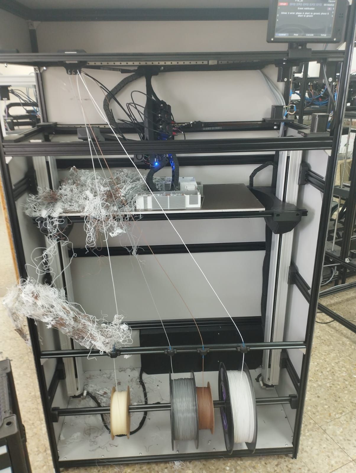
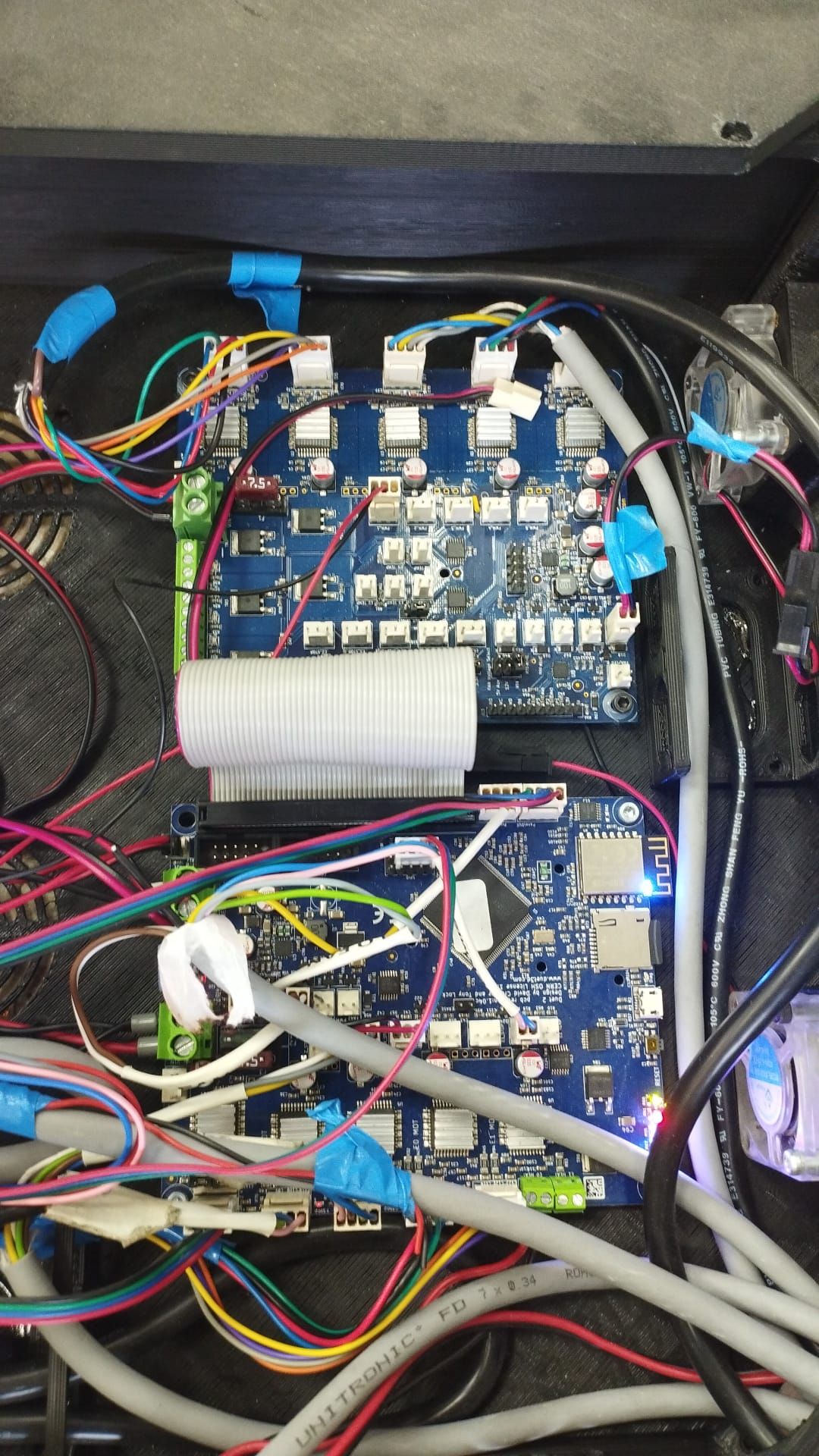
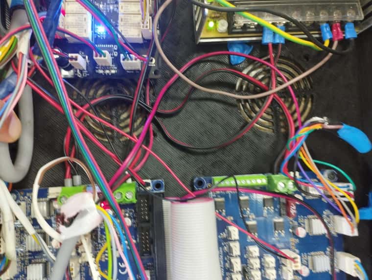
                                          @maor3degem-co-il Thank you for adding the pictures of the wiring.
                                          The M122.txt file you posted seems to be blank.
                                          I've added your config.g to your post, to make it easier to check, but I don't think that is causing the issue.
                                          It would be helpful if you could answer questions, rather than restating the issue each time.

                                          Currently, we think:

                                          • The issue is not caused by firmware or config. It's happening across all firmware versions you have tried, with firmware versions up to 3 years old (RRF 3.3). We would have other reports of this if it was a firmware issue. You have other machines that are not affected, running the same firmware and config.
                                          • The issue is unlikely to be caused by the Duet hardware. You could try swapping the Duet and Duex from a machine that has no issue, if you wanted to rule this out. But it would be very strange that 5 Duet/Duex boards suddenly have the same issue at the same time.
                                          • It is by far the most likely cause is that interference on the SPI bus via the ribbon cable is causing this issue.
                                          • It is also possible it is caused by an environmental issues (high heat and/or humidity), or a change in process (different filament), causing a change in static electricity build up. The issue seems to occur after an extended period of time printing, I think?

                                          I have already explained how to mitigate these issues:

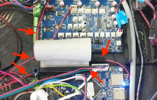
                                          1. Check/replace GND wire between Duet and Duex. A poor ground wire causes a potential difference on the GND pin between the Duet and Duex, and can cause interference. Your image shows the VIN/GND wire being longer than necessary. Wire a shorter ground wire, with a thicker gauge of wire, between the Duet and Duex.
                                            027a52e8-8290-45fc-a5de-51a93ce60da3-image.png
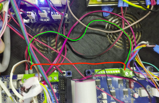
                                          2. Route other wires away from the ribbon cable. These ones seem close:
                                            17879089-9b69-4c55-8c0a-c4b6197553d5-image.png
                                          3. For static/ESD issues, make sure the hot end and extruder are grounded.

                                          Ian

                                          Bed-slinger - Mini5+ WiFi/1LC | RRP Fisher v1 - D2 WiFi | Polargraph - D2 WiFi | TronXY X5S - 6HC/Roto | CNC router - 6HC | Tractus3D T1250 - D2 Eth

                                          1 Reply Last reply Reply Quote 1
                                          • First post
                                            Last post
                                          Unless otherwise noted, all forum content is licensed under CC-BY-SA