Duet3D Logo Duet3D
    • Tags
    • Documentation
    • Order
    • Register
    • Login

    Home Z incorrect position

    Scheduled Pinned Locked Moved
    General Discussion
    5
    24
    445
    Loading More Posts
    • Oldest to Newest
    • Newest to Oldest
    • Most Votes
    Reply
    • Reply as topic
    Log in to reply
    This topic has been deleted. Only users with topic management privileges can see it.
    • OwenDundefined
      OwenD @SonnyD1
      last edited by

      @SonnyD1
      I'm afraid I know nothing about scanning probes, so I'll leave that for someone else

      1 Reply Last reply Reply Quote 0
      • dc42undefined
        dc42 administrators @SonnyD1
        last edited by

        @SonnyD1 do you have a mesh.g file in /sys on the SD card; if you do, what is in it?

        Duet WiFi hardware designer and firmware engineer
        Please do not ask me for Duet support via PM or email, use the forum
        http://www.escher3d.com, https://miscsolutions.wordpress.com

        1 Reply Last reply Reply Quote 0
        • droftartsundefined
          droftarts administrators @SonnyD1
          last edited by

          @SonnyD1 After you have done the calibration, you run G29, which runs mesh.g to do the actual mesh scan. See https://docs.duet3d.com/en/User_manual/Tuning/scanning_z_probe_calibration#example-meshg-file

          Ian

          Bed-slinger - Mini5+ WiFi/1LC | RRP Fisher v1 - D2 WiFi | Polargraph - D2 WiFi | TronXY X5S - 6HC/Roto | CNC router - 6HC | Tractus3D T1250 - D2 Eth

          SonnyD1undefined 1 Reply Last reply Reply Quote 0
          • SonnyD1undefined
            SonnyD1 @droftarts
            last edited by

            @droftarts Here is the mesh.g file again:

            M557 X25:175 Y25:175 P10     ; Define grid for mesh bed compensation, origin in bed centre
            G29 S2                       ; Disable mesh bed compensation
            G28 Z                        ; Home Z
            G1 Z6                        ; To avoid backlash move to point higher than start of calibration
            M558.1 K1 S2                 ; Calibrate probe
            G1 Z6
            

            When I give it a G29 command from the console, all it does is home Z then calibrates the the scanner. How do I get it to scan the bed and create a mesh? I assume the problem is in the mesh.g but I copied it from the documentation.

            jay_s_ukundefined 1 Reply Last reply Reply Quote 0
            • jay_s_ukundefined
              jay_s_uk @SonnyD1
              last edited by

              @SonnyD1 remove the S2 from the G29

              Owns various duet boards and is the main wiki maintainer for the Teamgloomy LPC/STM32 port of RRF. Assume I'm running whatever the latest beta/stable build is

              droftartsundefined 1 Reply Last reply Reply Quote 0
              • droftartsundefined
                droftarts administrators @jay_s_uk
                last edited by droftarts

                @jay_s_uk @SonnyD1

                remove the S2 from the G29

                No, that's in the right place, and makes sure you're scanning with no mesh applied. What's actually missing from the example is G29 S0 K1 after the calibration, i.e. after the last line. Sorry about that, I'll add it.

                Edit: You can also add moves at the end to home z (usually sensible after mesh creation), and move to a sensible place ready to start printing, if not already there after homing z.

                Ian

                Bed-slinger - Mini5+ WiFi/1LC | RRP Fisher v1 - D2 WiFi | Polargraph - D2 WiFi | TronXY X5S - 6HC/Roto | CNC router - 6HC | Tractus3D T1250 - D2 Eth

                SonnyD1undefined 2 Replies Last reply Reply Quote 1
                • SonnyD1undefined
                  SonnyD1 @droftarts
                  last edited by

                  @droftarts I got a new error now: Error: Bad reading from scanning probe - try recalibrating the probe. I think its a height issue as it is very high from the bed. Like 8mm high. I do believe that being cause by another issue. I need to verify the steps/mm on my Z axis. I think it much higher than it thinks it is and can't complete the scan. Let me confirm.

                  1 Reply Last reply Reply Quote 0
                  • SonnyD1undefined
                    SonnyD1 @droftarts
                    last edited by SonnyD1

                    @droftarts Yea thats not it. When I home, for some reason it ends with the Nozzle 10mm above the bed (12mm for the SZP). When I execute a G29, it homes Z, calibrates the SZP, starts the scan but stops way short. Its attempting to scan at a measured height of 8mm. I'm no expert, but that doesn't seem right.
                    Before the error, the console answers with "g29
                    Scanning probe coefficients [5.032e-1, 4.463e-4, -3.360e-11, -4.840e-16], reading at trigger height 999999, rms error 0.466mm."

                    dc42undefined 1 Reply Last reply Reply Quote 0
                    • dc42undefined
                      dc42 administrators @SonnyD1
                      last edited by

                      @SonnyD1 after you home Z using the BLTouch, is the Z position accurate? For example, if you send G1 Z1 does the nozzle move to 1mm above the bed?

                      The scan should proceed with the nozzle height equal to the trigger height that you set for the scanning probe, which you have set to 3mm in your G31 K1 command in config.g.

                      Duet WiFi hardware designer and firmware engineer
                      Please do not ask me for Duet support via PM or email, use the forum
                      http://www.escher3d.com, https://miscsolutions.wordpress.com

                      SonnyD1undefined 1 Reply Last reply Reply Quote 0
                      • SonnyD1undefined
                        SonnyD1 @dc42
                        last edited by

                        @dc42 After I home with the BLTouch, the position is accurate. I fixed that yesterday so the nozzle does in fact move to 1mm above the bed on command. I've measured that the SZP is 2.7mm above the nozzle and the trigger height on the BLTouch is now accurate. What number should I have for the trigger height on the SZP and how do I get it? attaching an updated config.

                        ; Configuration file for RepRapFirmware on Duet 3 Mini 5+ WiFi
                        ; executed by the firmware on start-up
                        ;
                        ; generated by RepRapFirmware Configuration Tool v3.5.4 on Sat Aug 10 2024 17:00:36 GMT-0400 (Eastern Daylight Time)
                         
                        ; General
                        G90                                                             ; absolute coordinates
                        M83                                                             ; relative extruder moves
                        M550 P"M3ID V2"                                                 ; set hostname
                         
                        ; Accessories
                        M575 P1 S0 B57600                                               ; configure PanelDue support
                         
                        ; Network
                        M552 S1                                                         ; configure WiFi adapter
                        M586 P0 S1                                                      ; configure HTTP
                         
                        ; Wait a moment for the CAN expansion boards to become available
                        G4 S2
                         
                        ; Accelerometers
                        M955 P121.0 I20                                                 ; configure accelerometer on board #121
                        M955 P122.0 I20                                                 ; configure accelerometer on board #122
                         
                        ; Smart Drivers
                        M569 P0.1 S0 D2                                                 ; driver 0.1 goes backwards (X axis)
                        M569 P0.2 S1 D2                                                 ; driver 0.2 goes forwards (Y axis)
                        M569 P0.3 S0 D2                                                 ; driver 0.3 goes backwards (Z axis)
                        M569 P0.4 S0 D2                                                 ; driver 0.4 goes forwards (U axis)
                        M569 P121.0 S1 D2                                               ; driver 121.0 goes forwards (extruder 0)
                        M569 P122.0 S1 D2                                               ; driver 122.0 goes forwards (extruder 1)
                         
                        ; Motor Idle Current Reduction
                        M906 I30                                                        ; set motor current idle factor
                        M84 S30                                                         ; set motor current idle timeout
                         
                        ; Axes
                        M584 X0.1 Y0.2 Z0.3 U0.4                                        ; set axis mapping
                        M350 X16 Y16 Z16 U16 I1                                         ; configure 16X microstepping with interpolation
                        M906 X1750 Y1750 Z800 U1750                                     ; set axis driver currents
                        M92 X80 Y88 Z1010 U80                                           ; configure steps per mm
                        M208 X-7:203 Y-9:250 Z0:200 U28:258                             ; set minimum and maximum axis limits
                        M566 X900 Y900 Z12 U900                                         ; set maximum instantaneous speed changes (mm/min)
                        M203 X6000 Y6000 Z180 U6000                                     ; set maximum speeds (mm/min)
                        M201 X500 Y500 Z20 U500                                         ; set accelerations (mm/s^2)
                         
                        ; Extruders
                        M584 E121.0:122.0                                               ; set extruder mapping
                        M350 E16:16 I1                                                  ; configure microstepping with interpolation
                        M906 E424:424                                                   ; set extruder driver currents
                        M92 E2682:2682                                                  ; configure steps per mm
                        M566 E150:150                                                   ; set maximum instantaneous speed changes (mm/min)
                        M203 E3600:3600                                                 ; set maximum speeds (mm/min)
                        M201 E3000:3000                                                 ; set accelerations (mm/s^2)
                         
                        ; Kinematics
                        M669 K0                                                         ; configure Cartesian kinematics
                         
                        ; BLtouch
                        M558 K0 P9 C"121.io0.in" H5 F8000:120 T6000                     ; configure BLTouch probe via slot #0
                        G31 P500 X0 Y24 Z4.249                                          ; set Z probe trigger value, offset and trigger height
                        M950 S0 C"121.io0.out"                                          ; create servo #0 for BLtouch
                         
                        ; Scanning Z probe
                        M558 K1 P11 C"121.i2c.ldc1612" F36000 T36000
                        M308 A"SZP coil" S10 Y"thermistor" P"121.temp2"                 ; thermistor on coil
                        G31 K1 Z3 Y-38                                                  ; define probe 1 offsets and trigger height
                        M558.2 K1 S17 R136464                                           ; set drive current and reading offset
                         
                        ; Endstops
                        M574 X1 P"io1.in" S1                                            ; configure X axis low end endstop
                        M574 Y1 P"io2.in" S1                                            ; configure Y axis low end endstop
                        M574 Z2 S1 P"io3.in"                                            ; configure Z axis high end endstop
                        M574 U2 P"io4.in" S1                                            ; configure U axis high end endstop
                         
                        ; Mesh Bed Compensation
                        M557 X25:175 Y25:175 S40:40                                     ; define grid for mesh bed compensation
                         
                        ; Sensors
                        M308 S0 P"temp0" Y"thermistor" A"Heated Bed" T100000 B4725 C7.06e-8 ; configure sensor #0
                        M308 S1 P"121.temp1" Y"thermistor" A"Nozzle" T100000 B4725 C7.06e-8 ; configure sensor #1
                        M308 S2 P"122.temp0" Y"thermistor" A"Nozzle" T100000 B4725 C7.06e-8 ; configure sensor #2
                         
                        ; Heaters
                        M950 H0 C"out2" T0                                              ; create heater #0 (Bed)
                        M143 H0 P0 T0 C0 S120 A0                                        ; configure heater monitor #0 for heater #0 (Bed)
                        M307 H0 R0.167 K0.222:0.000 D26.05 E1.35 S1.00 B0               ; configure model of heater #0 (Bed)
                        M950 H1 C"121.out0" T1                                          ; create heater #1 (T0)
                        M143 H1 P0 T1 C0 S300 A0                                        ; configure heater monitor #0 for heater #1 (T0)
                        M307 H1 R4.287 K0.528:0.232 D2.33 E1.35 S1.00 B0 V24.1          ; configure model of heater #1 (T0)
                        M950 H2 C"122.out0" T2                                          ; create heater #2 (T1)
                        M143 H2 P0 T1 C0 S300 A0                                        ; configure heater monitor #0 for heater #2 (T1)
                        M307 H2 R4.334 K0.514:0.239 D2.21 E1.35 S1.00 B0 V24.0          ; configure model of heater #2 (T1)
                         
                        ; Heated beds
                        M140 P0 H0                                                      ; configure heated bed #0
                         
                        ; Fans
                        M950 F0 C"121.out2"                                             ; create fan #0 T0 Heat Sink Fan
                        M106 P0 C"T0 Heatsink Fan" S0 B0.1 H1 T45                       ; configure fan #0 T0 Heat Sink Fan
                        M950 F1 C"121.out1"                                             ; create fan #1 T0 Part Cooling fan
                        M106 P1 C"T0 Part Cooling Fan" S0 L25 X255 B0.1                 ; configure fan #1 T0 Part Cooling Fan
                        M950 F2 C"122.out2"                                             ; create fan #2 T1 Heat Sink Fan
                        M106 P2 C"T1 Heatsink Fan" S0 B0.1 H2 T45                       ; configure fan #2 T1 Heat Sink Fan
                        M950 F3 C"122.out1"                                             ; create fan #3 T1 Part Cooling Fan
                        M106 P3 C"T1 Part Cooling Fan" S0 L25 X255 B0.1                 ; configure fan #3 T1 Part Cooling Fan
                         
                        ; Tools
                        M563 P0 D0 H1 F1                                                ; create tool #0 T0
                        M568 P0 R0 S0                                                   ; set initial tool #0 active and standby temperatures to 0C
                        M563 P1 D1 H2 F3                                                ; create tool #1 T1
                        M568 P1 R0 S0                                                   ; set initial tool #1 active and standby temperatures to 0C
                         
                        ; Miscellaneous
                        T0 ; select first tool
                        
                        
                        dc42undefined 1 Reply Last reply Reply Quote 0
                        • dc42undefined
                          dc42 administrators @SonnyD1
                          last edited by

                          @SonnyD1 the scanning nozzle height should be the Z parameter in your G31 K1 command. You appear to have set this as 3mm in your G31 K1 command. You can send G31 K1 to check that it hasn't changed. It's reported as the trigger height.

                          You could also try setting the dive height (H parameter) in your M558 K1 command, although I don't think that should matter.

                          Duet WiFi hardware designer and firmware engineer
                          Please do not ask me for Duet support via PM or email, use the forum
                          http://www.escher3d.com, https://miscsolutions.wordpress.com

                          SonnyD1undefined 1 Reply Last reply Reply Quote 0
                          • SonnyD1undefined
                            SonnyD1 @dc42
                            last edited by SonnyD1

                            @dc42 The G31 K1 response:

                            G31 K1
                            Z probe 1: current reading 2467, threshold 500, trigger height 3.000, offsets X0.0 Y-38.0 U0.0

                            Do I need to change it?

                            droftartsundefined 1 Reply Last reply Reply Quote 0
                            • droftartsundefined
                              droftarts administrators @SonnyD1
                              last edited by

                              @SonnyD1 Follow the setup and calibration documentation: https://docs.duet3d.com/en/User_manual/Tuning/scanning_z_probe_calibration

                              • Your SZP is 2.7mm above the nozzle. Currently G31 Z3 is set. This means the probe should be triggering at 5.7mm. This is a bit high (we recommend in the range 4 to 5mm). I think reduce G31 to Z2, unless your bed is very warped (over +1mm).
                              • Your M558.2 S parameter is high, at S17. Which coil are you using (12mm or 15mm)? Being a bit lower to the bed (with G31 Z2) will most likely change this.

                              After that, follow the 'initial calibration' steps. I have updated the instructions to make them clearer.

                              Ian

                              Bed-slinger - Mini5+ WiFi/1LC | RRP Fisher v1 - D2 WiFi | Polargraph - D2 WiFi | TronXY X5S - 6HC/Roto | CNC router - 6HC | Tractus3D T1250 - D2 Eth

                              SonnyD1undefined 1 Reply Last reply Reply Quote 1
                              • SonnyD1undefined
                                SonnyD1 @droftarts
                                last edited by SonnyD1

                                @droftarts I am using the 12mm coil. The Calibration gave me a S parameter of 15. After I followed your instructions, I was able to complete the scan for the first time. However, I looks as though it should have done one more row. There's about 80mm of bed left unscanned. Also, I got a reply of:

                                Warning: the height map has a substantial Z offset. Suggest use Z-probe to establish Z=0 datum, then re-probe the mesh.
                                100 points probed, min error -0.275, max error -0.123, mean -0.220, deviation 0.041
                                Height map saved to file 0:/sys/heightmap.csv

                                How do I improve on that? Is it talking about Tram or a wavy bed? If its Tram the I can put I dial indicator on it to fix that. I'm going to continue to test at different heights pending your advice.

                                droftartsundefined 1 Reply Last reply Reply Quote 0
                                • droftartsundefined
                                  droftarts administrators @SonnyD1
                                  last edited by

                                  @SonnyD1 Can you post your current mesh.g file? I don't think the error is from scanning, more likely a mesh is being loaded before Z is homed, so the offset from the nozzle is incorrect.

                                  The scan is reporting a pretty flat bed, congratulations! The shape of the scan will show if you need to tram the rails linear rails, maybe take a screen shot of the mesh and post it.

                                  Ian

                                  Bed-slinger - Mini5+ WiFi/1LC | RRP Fisher v1 - D2 WiFi | Polargraph - D2 WiFi | TronXY X5S - 6HC/Roto | CNC router - 6HC | Tractus3D T1250 - D2 Eth

                                  SonnyD1undefined 2 Replies Last reply Reply Quote 0
                                  • SonnyD1undefined
                                    SonnyD1 @droftarts
                                    last edited by SonnyD1

                                    @droftarts I think I found why it left out so much. Bed size is not correct. Fixing it now in the mesh.g. The M557 line should read M557 X19:188 Y15:210 P10 . The info you asked for is below. Is this how we fix the height map warning?

                                    M557 X25:175 Y25:175 P10     ; Define grid for mesh bed compensation, origin in bed centre
                                    G29 S2                       ; Disable mesh bed compensation
                                    G28 Z                        ; Home Z
                                    G1 Z6                        ; To avoid backlash move to point higher than start of calibration
                                    M558.1 K1 S2                 ; Calibrate probe
                                    G1 Z6
                                    G29 S0 K1
                                    

                                    Screenshot 2024-12-02 201831.jpg

                                    1 Reply Last reply Reply Quote 0
                                    • SonnyD1undefined
                                      SonnyD1 @droftarts
                                      last edited by

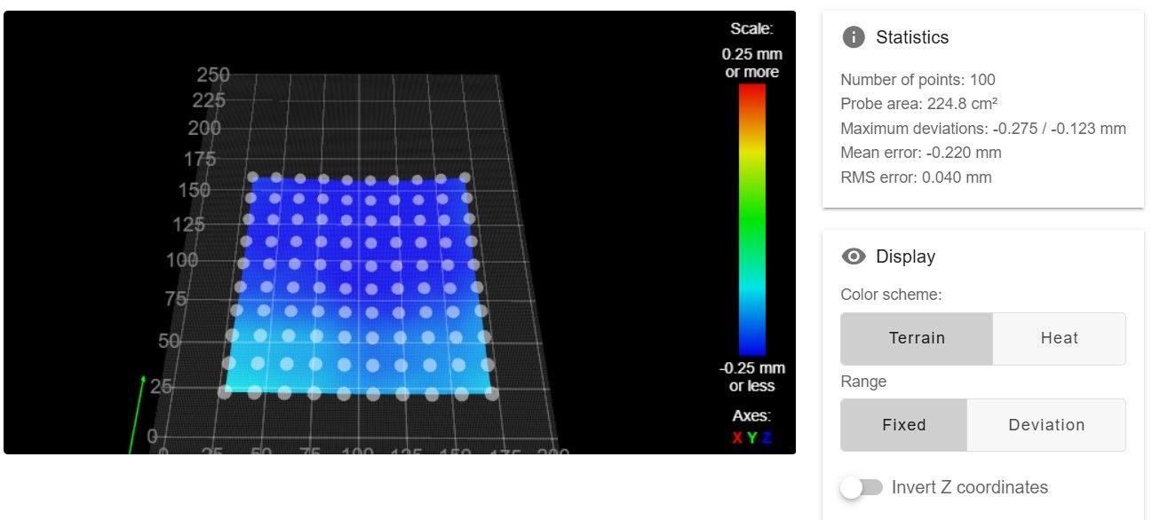
                                      @droftarts Have you given up on me? We're almost done! I'd like to eliminate the error if it's a problem. Let me know what I need to do.

                                      droftartsundefined 1 Reply Last reply Reply Quote 0
                                      • droftartsundefined
                                        droftarts administrators @SonnyD1
                                        last edited by

                                        @SonnyD1 Not given up, just busy! If you get the message after the SZP scan, I think most likely is that there is a difference between what the BLTouch thinks is Z0 and what the SZP thinks is Z0, with the difference being around 0.2mm. Or when you did the M558.2 calibration, the SZP was higher than Z2. Try doing this again.

                                        Also, if you have G31 Z2 set for the SZP, this is the height around which the M558.1 calibration is done. If you have the M558.1 S parameter set to 2mm, it calibrates +/-2mm around the trigger height (G31 Z2 ie 2mm) so from Z4 to Z0. This means the nozzle will touch the bed. Best to change M558.1 S parameter to something a little smaller, eg 1.7.

                                        Ian

                                        Bed-slinger - Mini5+ WiFi/1LC | RRP Fisher v1 - D2 WiFi | Polargraph - D2 WiFi | TronXY X5S - 6HC/Roto | CNC router - 6HC | Tractus3D T1250 - D2 Eth

                                        SonnyD1undefined 2 Replies Last reply Reply Quote 0
                                        • SonnyD1undefined
                                          SonnyD1 @droftarts
                                          last edited by

                                          @droftarts I did everything exactly as you suggested. I changed the M558 in both the config as well as the mesh.g to S1.7. Then, I meticulously went through the calibration steps. The G29 replied with in the console:

                                          G29
                                          Scanning probe coefficients [1.381e-1, -7.148e-4, -2.015e-8, 2.106e-14], reading at trigger height 8936, rms error 0.137mm

                                          After completion I got the following error in the console:

                                          Warning: the height map has a substantial Z offset. Suggest use Z-probe to establish Z=0 datum, then re-probe the mesh.
                                          100 points probed, min error -0.187, max error -0.035, mean -0.131, deviation 0.033
                                          Height map saved to file 0:/sys/heightmap.csv

                                          Here is the most recent config.g and mesh.g as well as a screenshot of the heightmap:

                                          ; Configuration file for RepRapFirmware on Duet 3 Mini 5+ WiFi
                                          ; executed by the firmware on start-up
                                          ;
                                          ; generated by RepRapFirmware Configuration Tool v3.5.4 on Sat Aug 10 2024 17:00:36 GMT-0400 (Eastern Daylight Time)
                                           
                                          ; General
                                          G90                                                             ; absolute coordinates
                                          M83                                                             ; relative extruder moves
                                          M550 P"M3ID V2"                                                 ; set hostname
                                           
                                          ; Accessories
                                          M575 P1 S0 B57600                                               ; configure PanelDue support
                                           
                                          ; Network
                                          M552 S1                                                         ; configure WiFi adapter
                                          M586 P0 S1                                                      ; configure HTTP
                                           
                                          ; Wait a moment for the CAN expansion boards to become available
                                          G4 S2
                                           
                                          ; Accelerometers
                                          M955 P121.0 I20                                                 ; configure accelerometer on board #121
                                          M955 P122.0 I20                                                 ; configure accelerometer on board #122
                                           
                                          ; Smart Drivers
                                          M569 P0.1 S0 D2                                                 ; driver 0.1 goes backwards (X axis)
                                          M569 P0.2 S1 D2                                                 ; driver 0.2 goes forwards (Y axis)
                                          M569 P0.3 S0 D2                                                 ; driver 0.3 goes backwards (Z axis)
                                          M569 P0.4 S0 D2                                                 ; driver 0.4 goes forwards (U axis)
                                          M569 P121.0 S1 D2                                               ; driver 121.0 goes forwards (extruder 0)
                                          M569 P122.0 S1 D2                                               ; driver 122.0 goes forwards (extruder 1)
                                           
                                          ; Motor Idle Current Reduction
                                          M906 I30                                                        ; set motor current idle factor
                                          M84 S30                                                         ; set motor current idle timeout
                                           
                                          ; Axes
                                          M584 X0.1 Y0.2 Z0.3 U0.4                                        ; set axis mapping
                                          M350 X16 Y16 Z16 U16 I1                                         ; configure 16X microstepping with interpolation
                                          M906 X1750 Y1750 Z800 U1750                                     ; set axis driver currents
                                          M92 X80 Y88 Z1010 U80                                           ; configure steps per mm
                                          M208 X-7:203 Y-9:250 Z0:200 U28:258                             ; set minimum and maximum axis limits
                                          M566 X900 Y900 Z12 U900                                         ; set maximum instantaneous speed changes (mm/min)
                                          M203 X6000 Y6000 Z180 U6000                                     ; set maximum speeds (mm/min)
                                          M201 X500 Y500 Z20 U500                                         ; set accelerations (mm/s^2)
                                           
                                          ; Extruders
                                          M584 E121.0:122.0                                               ; set extruder mapping
                                          M350 E16:16 I1                                                  ; configure microstepping with interpolation
                                          M906 E424:424                                                   ; set extruder driver currents
                                          M92 E2682:2682                                                  ; configure steps per mm
                                          M566 E150:150                                                   ; set maximum instantaneous speed changes (mm/min)
                                          M203 E3600:3600                                                 ; set maximum speeds (mm/min)
                                          M201 E3000:3000                                                 ; set accelerations (mm/s^2)
                                           
                                          ; Kinematics
                                          M669 K0                                                         ; configure Cartesian kinematics
                                           
                                          ; BLtouch
                                          M558 K0 P9 C"121.io0.in" H5 F8000:120 T6000                     ; configure BLTouch probe via slot #0
                                          G31 P500 X0 Y24 Z4.249                                          ; set Z probe trigger value, offset and trigger height
                                          M950 S0 C"121.io0.out"                                          ; create servo #0 for BLtouch
                                           
                                          ; Scanning Z probe
                                          M558 K1 P11 C"121.i2c.ldc1612" F36000 T36000
                                          M308 A"SZP coil" S10 Y"thermistor" P"121.temp2"                 ; thermistor on coil
                                          G31 K1 Z1.7 Y-38                                                ; define probe 1 offsets and trigger height
                                          M558.2 K1 S16 R134312                                           ; set drive current and reading offset
                                           
                                          ; Endstops
                                          M574 X1 P"io1.in" S1                                            ; configure X axis low end endstop
                                          M574 Y1 P"io2.in" S1                                            ; configure Y axis low end endstop
                                          M574 Z2 S1 P"io3.in"                                            ; configure Z axis high end endstop
                                          M574 U2 P"io4.in" S1                                            ; configure U axis high end endstop
                                           
                                          ; Mesh Bed Compensation
                                          M557 X19:188 Y15:210 S40:40                                     ; define grid for mesh bed compensation
                                           
                                          ; Sensors
                                          M308 S0 P"temp0" Y"thermistor" A"Heated Bed" T100000 B4725 C7.06e-8 ; configure sensor #0
                                          M308 S1 P"121.temp1" Y"thermistor" A"Nozzle" T100000 B4725 C7.06e-8 ; configure sensor #1
                                          M308 S2 P"122.temp0" Y"thermistor" A"Nozzle" T100000 B4725 C7.06e-8 ; configure sensor #2
                                           
                                          ; Heaters
                                          M950 H0 C"out2" T0                                              ; create heater #0 (Bed)
                                          M143 H0 P0 T0 C0 S120 A0                                        ; configure heater monitor #0 for heater #0 (Bed)
                                          M307 H0 R0.167 K0.222:0.000 D26.05 E1.35 S1.00 B0               ; configure model of heater #0 (Bed)
                                          M950 H1 C"121.out0" T1                                          ; create heater #1 (T0)
                                          M143 H1 P0 T1 C0 S300 A0                                        ; configure heater monitor #0 for heater #1 (T0)
                                          M307 H1 R4.287 K0.528:0.232 D2.33 E1.35 S1.00 B0 V24.1          ; configure model of heater #1 (T0)
                                          M950 H2 C"122.out0" T2                                          ; create heater #2 (T1)
                                          M143 H2 P0 T1 C0 S300 A0                                        ; configure heater monitor #0 for heater #2 (T1)
                                          M307 H2 R4.334 K0.514:0.239 D2.21 E1.35 S1.00 B0 V24.0          ; configure model of heater #2 (T1)
                                           
                                          ; Heated beds
                                          M140 P0 H0                                                      ; configure heated bed #0
                                           
                                          ; Fans
                                          M950 F0 C"121.out2"                                             ; create fan #0 T0 Heat Sink Fan
                                          M106 P0 C"T0 Heatsink Fan" S0 B0.1 H1 T45                       ; configure fan #0 T0 Heat Sink Fan
                                          M950 F1 C"121.out1"                                             ; create fan #1 T0 Part Cooling fan
                                          M106 P1 C"T0 Part Cooling Fan" S0 L25 X255 B0.1                 ; configure fan #1 T0 Part Cooling Fan
                                          M950 F2 C"122.out2"                                             ; create fan #2 T1 Heat Sink Fan
                                          M106 P2 C"T1 Heatsink Fan" S0 B0.1 H2 T45                       ; configure fan #2 T1 Heat Sink Fan
                                          M950 F3 C"122.out1"                                             ; create fan #3 T1 Part Cooling Fan
                                          M106 P3 C"T1 Part Cooling Fan" S0 L25 X255 B0.1                 ; configure fan #3 T1 Part Cooling Fan
                                           
                                          ; Tools
                                          M563 P0 D0 H1 F1                                                ; create tool #0 T0
                                          M568 P0 R0 S0                                                   ; set initial tool #0 active and standby temperatures to 0C
                                          M563 P1 D1 H2 F3                                                ; create tool #1 T1
                                          M568 P1 R0 S0                                                   ; set initial tool #1 active and standby temperatures to 0C
                                           
                                          ; Miscellaneous
                                          T0 ; select first tool
                                          
                                          
                                          M557 X19:188 Y15:210 P10     ; Define grid for mesh bed compensation, origin in bed centre
                                          G29 S2                       ; Disable mesh bed compensation
                                          G28 Z                        ; Home Z
                                          G1 Z6                        ; To avoid backlash move to point higher than start of calibration
                                          M558.1 K1 S1.7               ; Calibrate probe
                                          G1 Z6
                                          G29 S0 K1
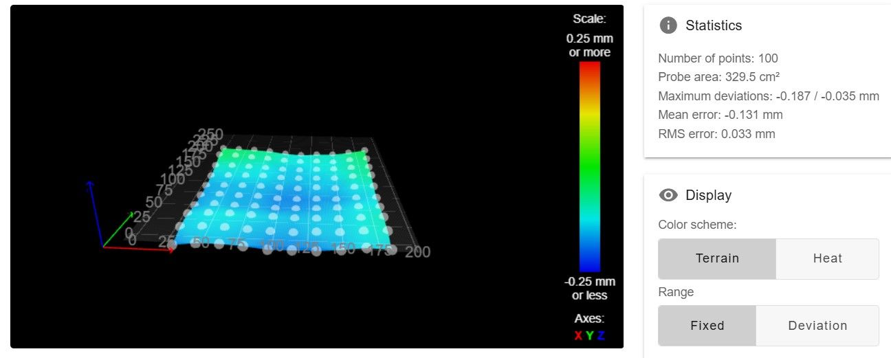
                                          

                                          Screenshot 2024-12-05 183435.jpg .

                                          I can say for certain that the BLTouch offset is accurate. It may be worth noting that the M558.2 S parameter changed to 16 with the new trigger height. I know I'm close but I can't seem to figure out what I'm missing. Maybe I could just try different trigger heights ranging from 1.6 to 2.0 and see what that does? I am at your disposal. Thank you for the help!

                                          1 Reply Last reply Reply Quote 0
                                          • SonnyD1undefined
                                            SonnyD1 @droftarts
                                            last edited by

                                            @droftarts After hours of trial and error and reading and trial and error and a bit more reading, I got it to work without the error. I feel like you abandoned me, but I understand that I and the machine were being difficult. In any case, I am attaching my new config.g, mesh.g and a screenshot of the heightmap. Thank you for getting me to the point that I could work through and solve it. Hopefully this will help somebody else.

                                            ; Configuration file for RepRapFirmware on Duet 3 Mini 5+ WiFi
                                            ; executed by the firmware on start-up
                                            ;
                                            ; generated by RepRapFirmware Configuration Tool v3.5.4 on Sat Aug 10 2024 17:00:36 GMT-0400 (Eastern Daylight Time)
                                             
                                            ; General
                                            G90                                                             ; absolute coordinates
                                            M83                                                             ; relative extruder moves
                                            M550 P"M3ID V2"                                                 ; set hostname
                                             
                                            ; Accessories
                                            M575 P1 S0 B57600                                               ; configure PanelDue support
                                             
                                            ; Network
                                            M552 S1                                                         ; configure WiFi adapter
                                            M586 P0 S1                                                      ; configure HTTP
                                             
                                            ; Wait a moment for the CAN expansion boards to become available
                                            G4 S2
                                             
                                            ; Accelerometers
                                            M955 P121.0 I20                                                 ; configure accelerometer on board #121
                                            M955 P122.0 I20                                                 ; configure accelerometer on board #122
                                             
                                            ; Smart Drivers
                                            M569 P0.1 S0 D2                                                 ; driver 0.1 goes backwards (X axis)
                                            M569 P0.2 S1 D2                                                 ; driver 0.2 goes forwards (Y axis)
                                            M569 P0.3 S0 D2                                                 ; driver 0.3 goes backwards (Z axis)
                                            M569 P0.4 S0 D2                                                 ; driver 0.4 goes forwards (U axis)
                                            M569 P121.0 S1 D2                                               ; driver 121.0 goes forwards (extruder 0)
                                            M569 P122.0 S1 D2                                               ; driver 122.0 goes forwards (extruder 1)
                                             
                                            ; Motor Idle Current Reduction
                                            M906 I30                                                        ; set motor current idle factor
                                            M84 S30                                                         ; set motor current idle timeout
                                             
                                            ; Axes
                                            M584 X0.1 Y0.2 Z0.3 U0.4                                        ; set axis mapping
                                            M350 X16 Y16 Z16 U16 I1                                         ; configure 16X microstepping with interpolation
                                            M906 X1750 Y1750 Z800 U1750                                     ; set axis driver currents
                                            M92 X80 Y88 Z1010 U80                                           ; configure steps per mm
                                            M208 X-7:203 Y-9:250 Z0:200 U28:258                             ; set minimum and maximum axis limits
                                            M566 X900 Y900 Z12 U900                                         ; set maximum instantaneous speed changes (mm/min)
                                            M203 X6000 Y6000 Z180 U6000                                     ; set maximum speeds (mm/min)
                                            M201 X500 Y500 Z20 U500                                         ; set accelerations (mm/s^2)
                                             
                                            ; Extruders
                                            M584 E121.0:122.0                                               ; set extruder mapping
                                            M350 E16:16 I1                                                  ; configure microstepping with interpolation
                                            M906 E424:424                                                   ; set extruder driver currents
                                            M92 E2682:2682                                                  ; configure steps per mm
                                            M566 E150:150                                                   ; set maximum instantaneous speed changes (mm/min)
                                            M203 E3600:3600                                                 ; set maximum speeds (mm/min)
                                            M201 E3000:3000                                                 ; set accelerations (mm/s^2)
                                             
                                            ; Kinematics
                                            M669 K0                                                         ; configure Cartesian kinematics
                                             
                                            ; BLtouch
                                            M558 K0 P9 C"121.io0.in" H5 F8000:120 T6000                     ; configure BLTouch probe via slot #0
                                            G31 P500 X0 Y24 Z4.3                                          ; set Z probe trigger value, offset and trigger height
                                            M950 S0 C"121.io0.out"                                          ; create servo #0 for BLtouch
                                             
                                            ; Scanning Z probe
                                            M558 K1 P11 C"121.i2c.ldc1612" F36000 T36000
                                            M308 A"SZP coil" S10 Y"thermistor" P"121.temp2"                 ; thermistor on coil
                                            G31 K1 Z1.8 Y-38                                                ; define probe 1 offsets and trigger height
                                            M558.2 K1 S16 R134218                                           ; set drive current and reading offset
                                             
                                            ; Endstops
                                            M574 X1 P"io1.in" S1                                            ; configure X axis low end endstop
                                            M574 Y1 P"io2.in" S1                                            ; configure Y axis low end endstop
                                            M574 Z2 S1 P"io3.in"                                            ; configure Z axis high end endstop
                                            M574 U2 P"io4.in" S1                                            ; configure U axis high end endstop
                                             
                                            ; Mesh Bed Compensation
                                            M557 X19:188 Y15:210 S40:40                                     ; define grid for mesh bed compensation
                                             
                                            ; Sensors
                                            M308 S0 P"temp0" Y"thermistor" A"Heated Bed" T100000 B4725 C7.06e-8 ; configure sensor #0
                                            M308 S1 P"121.temp1" Y"thermistor" A"Nozzle" T100000 B4725 C7.06e-8 ; configure sensor #1
                                            M308 S2 P"122.temp0" Y"thermistor" A"Nozzle" T100000 B4725 C7.06e-8 ; configure sensor #2
                                             
                                            ; Heaters
                                            M950 H0 C"out2" T0                                              ; create heater #0 (Bed)
                                            M143 H0 P0 T0 C0 S120 A0                                        ; configure heater monitor #0 for heater #0 (Bed)
                                            M307 H0 R0.167 K0.222:0.000 D26.05 E1.35 S1.00 B0               ; configure model of heater #0 (Bed)
                                            M950 H1 C"121.out0" T1                                          ; create heater #1 (T0)
                                            M143 H1 P0 T1 C0 S300 A0                                        ; configure heater monitor #0 for heater #1 (T0)
                                            M307 H1 R4.287 K0.528:0.232 D2.33 E1.35 S1.00 B0 V24.1          ; configure model of heater #1 (T0)
                                            M950 H2 C"122.out0" T2                                          ; create heater #2 (T1)
                                            M143 H2 P0 T1 C0 S300 A0                                        ; configure heater monitor #0 for heater #2 (T1)
                                            M307 H2 R4.334 K0.514:0.239 D2.21 E1.35 S1.00 B0 V24.0          ; configure model of heater #2 (T1)
                                             
                                            ; Heated beds
                                            M140 P0 H0                                                      ; configure heated bed #0
                                             
                                            ; Fans
                                            M950 F0 C"121.out2"                                             ; create fan #0 T0 Heat Sink Fan
                                            M106 P0 C"T0 Heatsink Fan" S0 B0.1 H1 T45                       ; configure fan #0 T0 Heat Sink Fan
                                            M950 F1 C"121.out1"                                             ; create fan #1 T0 Part Cooling fan
                                            M106 P1 C"T0 Part Cooling Fan" S0 L25 X255 B0.1                 ; configure fan #1 T0 Part Cooling Fan
                                            M950 F2 C"122.out2"                                             ; create fan #2 T1 Heat Sink Fan
                                            M106 P2 C"T1 Heatsink Fan" S0 B0.1 H2 T45                       ; configure fan #2 T1 Heat Sink Fan
                                            M950 F3 C"122.out1"                                             ; create fan #3 T1 Part Cooling Fan
                                            M106 P3 C"T1 Part Cooling Fan" S0 L25 X255 B0.1                 ; configure fan #3 T1 Part Cooling Fan
                                             
                                            ; Tools
                                            M563 P0 D0 H1 F1                                                ; create tool #0 T0
                                            M568 P0 R0 S0                                                   ; set initial tool #0 active and standby temperatures to 0C
                                            M563 P1 D1 H2 F3                                                ; create tool #1 T1
                                            M568 P1 R0 S0                                                   ; set initial tool #1 active and standby temperatures to 0C
                                             
                                            ; Miscellaneous
                                            T0 ; select first tool
                                            
                                            
                                            M557 X19:188 Y15:210 P10     ; Define grid for mesh bed compensation, origin in bed centre
                                            G29 S2                       ; Disable mesh bed compensation
                                            G28 Z                       ; Home Z
                                            G1 Z6                        ; To avoid backlash move to point higher than start of calibration
                                            M558.1 K1 S1.4               ; Calibrate probe
                                            G1 Z6
                                            G29 S0 K1
                                            

                                            Screenshot 2024-12-17 151833.jpg

                                            droftartsundefined 1 Reply Last reply Reply Quote 1
                                            • First post
                                              Last post
                                            Unless otherwise noted, all forum content is licensed under CC-BY-SA