Sovol SV08 Multiple Motion System Upgrade.
-
New build plan - based on INDX - which I think looks a lot less complicated than my previous attempt
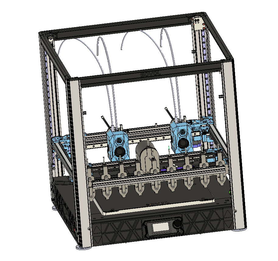
Phase 1 - Dual Gantry, Multi Motion System - current phase - still working on refining macro's and reliability.
Phase 2 -
DualIdex on rear gantry only (3 heads) - CoreXYUVW - Still a good testing point for additional kinematics, and avoids the need for motors at the bottom front.
Phase 3 - Occasionally moving bed - to allow for bigger prints, and for all heads to access full Y extent of bed.
Phase 4 - Nozzle Changer - with INDX on front gantry
Print types
- Small single colour - using just INDX head on front gantry
- Big Single colour - parallel printing with all 3 heads
- Small multi colour - Most common 2 colours in rear heads, plus 2 of the INDX slots - most colour changes would then be cross gantry parallel changes - so almost instant
- Big multi colour - As Small multi colour - but with some parallel printing too.
- Duplicate prints - - up to 3x speed for single colour using all 3 heads
Phase 5 - Only if enough benefits seen from IDEX - Add 4th head - as IDEX on Front Gantry, possibly with stealth changer offload ability for fast non IDEX printing.
Phase 4 - AMS - ideally finding a way to connect Bambu Lab AMSs - if not some sort of MMU solution - which will need more Mini5s -
For a moment, it looked like you were going to mount a second INDX on the back of the front gantry!
Ian
Bed-slinger - Mini5+ WiFi/1LC | RRP Fisher v1 - D2 WiFi | Polargraph - D2 WiFi | TronXY X5S - 6HC/Roto | CNC router - 6HC | Tractus3D T1250 - D2 Eth
-
@droftarts haven't ruled out anything yet about the direction of heads on gantries - but I hadn't thought of opposite directions on the same gantry.
Thinking about it - it might actually make the belt routing a bit simpler as have a linear on each side - as the belts wouldn't need to cross the linear rail carriages.
-
Been working today on tidying up probing and tool change macros which is proving quite difficult.
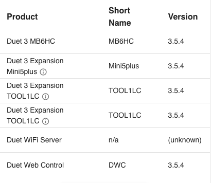
I'm currently on 3.5.4

Biggest issue I am having is with occasional 'Tool is in use or Axis is in use messages' - the biggest problem with these are that they don't stop execution so a) It can cause head clashes and b) They are quick tricky to track down.
I got a surprising tool temperature requirement - absolute zero - which I need to try and track down the cause.
UPDATE: Solved this issue - I had missed out the S on my M568 - so just had 0 - handy to know for the future.Also I am getting some quite strange behaviour with the U and Z axis - where sometimes when I do a Z move down it seems to also move U left (probably to where X currently is).
If I then move Z up again and U right - it goes a lot further than I am asking - presumably back to its proper position.
It's interesting seeing the head move in 45 degrees - but it is messing up my probing.
See <<< on line 74 in here for the place where it does the strange move.
Update - Solved - I removed all T0 and T1 commands from alignment/homing/cleaning sequences and that seems to have stopped the odd behaviour.
It left the possibility of parts of the macro's being multi threaded by replacing all T0,T1's with M596.1 T0/T1 - which will still do the tool switches when needed.;AlignUVZ.g ; if exists(global.ballProbeX) == false abort "XY alignment not found" G90 G1 Z50 F10000 T0 G1 X30 Y30 F20000 M400 M98 P"0:/macros/FindProbeUV.g" M574 Z1 S2 K3; Set Z to Ball Probe G1 H4 Z{global.zHit-1} F300 if sensors.probes[3].value[0] = 0 echo "Probe not found" break ;G1 U204 V149 F10000 T1 ; Find basic Z position var Zpos = {50,49,48,48,48} var Zrate = {300,200,100,100,100} var Upos = {10,8,8,8,8} var Vpos = {10,8,8,8,8} var UVrate = {1000,800,300,300,300} var prev = false var pVM = 0 var pUM = 0 var VM=0 var UM=0 while iterations < 2 M574 Z1 S2 K3; Set Z to Ball Probe G90 G1 Z{var.Zpos[iterations]} F300 G91 G1 H4 Z-12 F{var.Zrate[iterations]} ;echo "Z", {move.axes[2].userPosition} var ZP = move.axes[2].userPosition G1 Z5 F5000 M574 Z1 S2 K0; configure Z axis endstop ; Now find U middle G91 G1 U{0-var.Upos[iterations]} F5000 G90 G1 Z{var.ZP-0.2} F300 G91 M574 U1 S2 K3 ; Configure U axis with Z ball probe G1 H4 U+10 F{var.UVrate[iterations]} ;echo "X1", {move.axes[0].userPosition} M400 var U1 = move.axes[3].userPosition G1 Z5 F300 G1 U{var.Upos[iterations]} F5000 G1 Z-5 ; <<< Strange move - where it also moves U back M400 G1 H4 U-10 F{var.UVrate[iterations]} ;echo "X2", {move.axes[0].userPosition} M400 var U2 = move.axes[3].userPosition G1 Z5 G90 set var.UM = (var.U1+var.U2)/2 ;echo "XM", {var.XM} G1 U{var.UM} M574 U2 P"!122.io0.in" S1 ; configure U axis endstop ; Now V G91 G1 V{0-var.Vpos[iterations]} F5000 G1 Z-5 F300 M574 V1 S2 K3 G1 H4 V+10 F{var.UVrate[iterations]} ;echo "Y1", {move.axes[1].userPosition} M400 var V1 = move.axes[4].userPosition G1 Z5 F300 G1 V{var.Vpos[iterations]} F5000 G1 Z-5 F300 G1 H4 V-10 F{var.UVrate[iterations]} ;echo "Y2", {move.axes[1].userPosition} M400 var V2 = move.axes[4].userPosition set var.VM = (var.V1 + var.V2) / 2 echo "UM", {var.UM},"VM", {var.VM},"ZP", {var.ZP},"---U1,2",{var.U1},{var.U2},"--V1,2",{var.V1},{var.V2} if (var.prev == true) echo "variation U:",{var.pUM-var.UM}, "V:", {var.pVM-var.VM} set var.pVM = var.VM set var.pUM = var.UM set var.prev = true G1 Z5 F300 G90 G1 U{var.UM} V{var.VM} F2000 M574 V2 P"io4.in" S1 ; U Axis optical M574 Z1 S2 K3; Set Z to Ball Probe G91 G1 H4 Z-5 var Z1 = move.axes[2].machinePosition echo "z1",{var.Z1} G1 Z5 F1000 G1 U4 F10000 G1 H4 Z-10 var Z2 = move.axes[2].machinePosition echo "z2",{var.Z2} G1 Z5 F1000 M574 Z1 S2 K0; configure Z axis endstop if var.Z1-var.Z2 < 1 echo "z1,z2",{var.Z1},{var.Z2} abort "possible issue with UV alignment" G90 var adjust = var.UM - global.ballProbeX echo "adjusting U",{global.ballProbeX - var.UM},"V",{global.ballProbeY - var.VM} G92 U{global.ballProbeX} V{global.ballProbeY} if exists(global.UVAdjusted) == false global UVAdjusted = trueI have written a little wrapper macro form M596 - M596.1 - which a) Has the ability for M596's to be switched off, and be allows the tool to be specified instead of the motion system.
NB/ At present my tools and motion systems are swapped round - i.e. T0 is in motion system 1, and T1 in ms 0 - This was due to issues I was having when I have a servo on T1 (UV axis) - so I may well swap them back around at some point.
;M596.1,g ;M596.1 P-1 ; Ignore M596.1 commands until P-2 if exists(global.M596_stat) == false global M596_stat = -1 if exists(param.P) if param.P < 0 set global.M596_stat = param.P else if global.M596_stat == -2 M596 P{param.P} if exists(param.T) && global.M596_stat == -2 if param.T == 0 M596 P1 T0 else M596 P0 T1 if exists(param.Z) && global.M596_stat == -2 M596 P0 T1 -
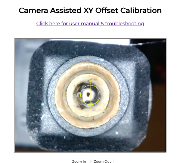
Ball probe Auto Alignment getting fairly good.
Images of nozzle as was found by printer with no manual adjustment or head movements.
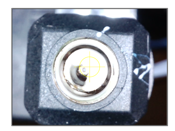
The alignment isn't perfectly on the centre of the nozzles in the camera because I can't guarantee the XY offset between the camera and ball probe - due to the swing out movement based on a servo - which might be a slightly different angle every time.
Checking with the camera I am getting a 0.1mm variation in the X/U axis, and 0.7mm in the Y/V axis.
Not sure if this a consistent difference or whether it varies.Not sure if this is dirty nozzles, nozzle shape irregularity or RRF Ball Probe macros' or just the sort of error you might get with a ball probe vs camera.
My XY Axis is still on sensorless end stops - so will be interesting to see what difference it makes swapping between sensorless and optical end stops in keeping alignment across reboots.
-
I think I just had a bright moment regarding z-hop: Re-purposing Rc-car servo savers could be the answer to more torque and accuracy, whilst still be backlash-free.
I tried to find a good picture to show how they work and came up with this:

Twisting the servo arm while the output-side is fixed to the tool head would be translated to vertical lift (or drop if you want to use gravity to your advance).
They usually come with an adjustable spring which isn't shown here. -
@o_lampe said in Sovol SV08 Multiple Motion System Upgrade.:
Rc-car servo savers
Thanks - are you suggesting having this attached to a non geared stepper motor, or a servo or somehow attaching it to the lead screw to translate big linear movements into smaller more powerful ones?
The final Nema8 I ordered just arrived and its a non lead screw 34 high vs most of the others which were 24 - so hopefully a bit more powerful.
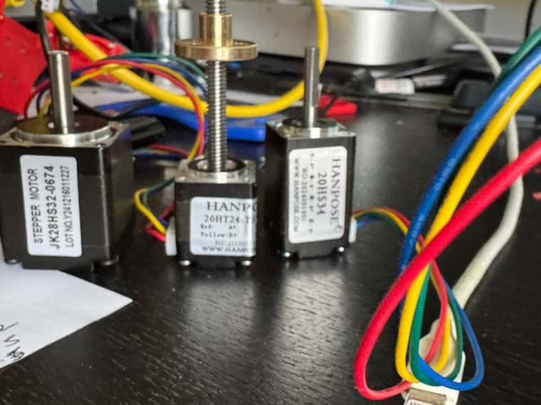
The Lead Screw Nema 11 still seems to be working quite well in my probing and Z offset tests - but haven't actually tried doing some proper printing with lots of Z Hopping yet. It is noticeably quicker than the tiny linear stepper that I had on the other axis - and I think will end up being quicker the geared belt driven Z Axis of the SV08
The good news with my current 3 rather than 4 headed next step is at least it means one less Z hopper motor to buy.
Shame I bought the 4th Extruder/ 1LC board and 2nd Mini5 - as I think I might be able to get away with the 16 drivers available on the 6HC, Mini5+, plus 3x1LC
Glad I haven't done to termination removal drill out on the Mini5+ board yet.
-
Work progressing on dual colour printing - example of auto alignment (it looked fairly good on the camera so I didn't adjust it at all).

Also made an extremely useful discovery about pre-heating - Orca Slicer (and probably PrusaSlicer and Bambu Studio supports it).
Example below with 2 seconds specified. - see 5th line down.
This will be very useful - because I can fairly easily change the G10 Pre-heats to be a macro call with a post processor - which can they do:
- More intelligent pre-heating based on the actual amount the inactive extruder has cooled - perhaps with some feedback to see how long it actually takes to reheat.
- Do the priming in parallel - so that as soon as in this example T0 has completed T1 can then start immediately printing - with hopefully almost no delay.
G1 X131.54 Y141.994 E.34619 G1 X131.54 Y142.652 E.02497 M73 P23 R1 G1 X137.336 Y148.448 E.31089 G10 S220 P1 ; preheat T1 time: 2s G1 X136.677 Y148.448 E.02497 G1 X131.54 Y143.31 E.27558 G1 X131.54 Y143.968 E.02497 G1 X136.019 Y148.448 E.24028 G1 X135.361 Y148.448 E.02497 G1 X131.54 Y144.627 E.20497 M73 P24 R1 G1 X131.54 Y145.285 E.02497 G1 X134.703 Y148.448 E.16966 G1 X134.044 Y148.448 E.02497 G1 X131.54 Y145.943 E.13436 G1 X131.54 Y146.601 E.02497 G1 X133.386 Y148.448 E.09905 G1 X132.728 Y148.448 E.02497 M73 P25 R1 G1 X131.54 Y147.259 E.06375 G1 X131.54 Y147.918 E.02497 G1 X132.275 Y148.654 E.03947 ; stop printing object Cube id:0 copy 0 ; printing object Cube id:1 copy 0 ; stop printing object Cube id:1 copy 0 G10 ; retract ; filament end gcode M106 P3 S0 G10 S215 P0 ; set nozzle temperature ;cooldown ;M98 P"0:/macros/changeFilament.g" A previous_extruder B new_filament_temp L layer_num N next_extruder F first_layer_temperature1 M98 P"0:/macros/changeFilament.g" A0 B220 L0 N1 F220 M106 S0 T1 ; Filament gcode G10 S220 P1 ; set nozzle temperature -
Simple post processing script created
#!/usr/bin/python3

# preheat - simple script to change all G10 & G11 commands to .1 versions - so that they run a Macro in RRF

# Based on example from Bobs Notebook. - https://projects.ttlexceeded.com/3dprinting_prusaslicer_post-processing.html


import sys
import re
import os


sourceFile=sys.argv[1]

# Read the ENTIRE g-code file into memory
with open(sourceFile, "r") as f:
    lines = f.readlines()

destFile = sourceFile
os.rename(sourceFile,sourceFile+".preheat.bak")

count = 0

with open(destFile, "w") as of:
    for lIndex in range(len(lines)):
        oline = lines[lIndex]
        # Parse gcode line

        if oline.startswith("G10 ") and "X0 " not in oline:
            oline = oline.replace("G10 ","G10.1 ")
            if "preheat" in oline:
                oline = oline.replace("G10.1 ","G10.1 Q1 ")
            count += 1

            of.write(oline);
        elif oline.startswith("G11 "):
            oline = oline.replace("G11 ","G11.1 ")
            count += 1

            of.write(oline);

        else:
            # Write original line
            of.write(oline)

    of.write(";****\n;****preheat " + str(count) + " lines changed\n")
of.close()
f.close()
Results - changing G10's all to G10.1 (except G10's with lots of AXIS parameters in).
M73 P23 R1
G1 X137.336 Y148.448 E.31089
G10.1 Q1 S220 P1 ; preheat T1 time: 2s
G1 X136.677 Y148.448 E.02497
G1 X131.54 Y143.31 E.27558
G1 X131.54 Y143.968 E.02497
G1 X136.019 Y148.448 E.24028
G1 X135.361 Y148.448 E.02497
G1 X131.54 Y144.627 E.20497
M73 P24 R1
G1 X131.54 Y145.285 E.02497
G1 X134.703 Y148.448 E.16966
G1 X134.044 Y148.448 E.02497
G1 X131.54 Y145.943 E.13436
G1 X131.54 Y146.601 E.02497
G1 X133.386 Y148.448 E.09905
G1 X132.728 Y148.448 E.02497
M73 P25 R1
G1 X131.54 Y147.259 E.06375
G1 X131.54 Y147.918 E.02497
G1 X132.275 Y148.654 E.03947
; stop printing object Cube id:0 copy 0
; printing object Cube id:1 copy 0
; stop printing object Cube id:1 copy 0
G10.1 ; retract
; filament end gcode
M106 P3 S0
G10.1 S215 P0 ; set nozzle temperature ;cooldown
;M98 P"0:/macros/changeFilament.g" A previous_extruder  B new_filament_temp  L layer_num  N next_extruder   F first_layer_temperature1

M98 P"0:/macros/changeFilament.g" A0 B220 L0  N1  F220


M106 S0
T1
; Filament gcode


....

;****preheat 21 lines changed
Now I just need to write the G10.1.g macro - to do the preheating and parallel priming.
-
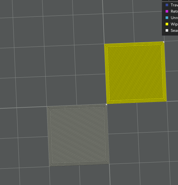
Parallel colour changes more or less working.
I used Orca Slicer to send 17 second pre-heating G10's
The preheat G10 comes in the opposite motion system to the one that needs the colour change to kick off.
So I used a loop within the next motion system to wait for the target temperature to change.- by checking heat.heaters[].active, and checking for temperature reached by looping around and checking sensors.analog[].lastReading.
Then once temperature reached I kicked off the priming, and then have a M598 just after the priming, but before the printing - so that the printer waits until the other motion system has finished it's work - before starting with the new colour.
The eventual aim would be to tune the preheat, and introduce a precisely timed delay so that the priming of the next colour finishes exactly when the other colour finishes.
For the SV08 heaters will need a longer preheat period - and will change the preheat to a tiny amount - so that I can pick up the change.
Will then depending on the current temperature either wait a bit, or kick of preheating straight away - with the heat up time calculated to leave exactly enough time for priming to be completed at exactly the same time as the other colour finishes printing.,
so that ideally the M598 at the end is pretty much instant.NB/. This way of working is only for small multi colour / multi material models. For bigger objects, where there is room on the print bed for both print heads to be printing at the same time, much more use of the RRF Multi Motion System capabilities will be made.
Short demo video here
https://youtu.be/Qn1SG_vc8X8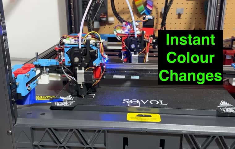
-
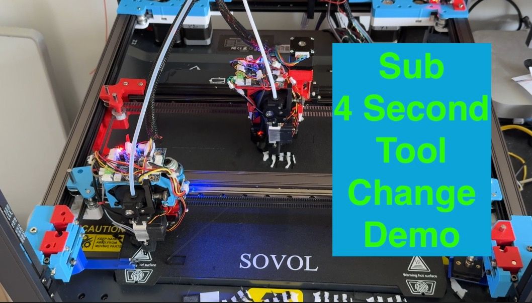
Better demo of parallel colour/material changes - some changes as quick as 2 seconds.
Still more work to do - but synchronisation getting closer.
Using preheat G10's to kicking off the Pre Heat, delay, final heat, priming, tool change.
Demo here.
Tool change macro getting pretty complicated....
;changeFilament.g ;M98 P"0:/macros/changeFilament.g" A{previous_extruder} B{new_filament_temp} L{layer_num} F{first_layer_temperature} N{next_extruder} H{first_layer_height} echo {state.thisInput},"changeFilament" if exists(global.primeLayer) == false global primeLayer = {-2,-2} ;if exists(param.A) && param.A == 0 ; M98.1 A"parkXY.g" ;if exists(param.A) && param.A == 1 ; M98.1 A"parkUV.g" if exists(param.H) G1 Z{param.H} F500 if exists(param.N) && param.N == 0 M596.1 P1 T0 echo {state.thisInput},"step 0 - wait for 200",{sensors.analog[param.N+1].lastReading} while heat.heaters[1].active < 200 G4 P500 ;echo {state.thisInput},"step 0 - wait for 200",{sensors.analog[param.N+1].lastReading} ;echo {state.thisInput},"M116 P1 from ",{sensors.analog[param.N+1].lastReading}," to 200" ;var start = state.upTime ;M116 P{param.N} ;echo {state.thisInput},"step 1 heat up time",{floor(state.upTime-var.start)},"s" ;**** Calculate delay var delayT = global.preHeatT echo {state.thisInput},"delayT initial",var.delayT if exists(param.L) && param.L <= 0 if global.primeLayer[param.N] < param.L set var.delayT = var.delayT - global.primeTime0*2 if exists(param.L) && param.L > 0 && global.primeLayer[param.N] < param.L set var.delayT = var.delayT - global.primeTime0 echo {state.thisInput},"delayT with prime",var.delayT ; post delay heatup var lastR = sensors.analog[param.N+1].lastReading if var.lastR < 200 set var.delayT = var.delayT - ((220-200)/global.degSec) if (200-var.lastR)/global.degSec > var.delayT set var.delayT = var.delayT - ((200-var.lastR)/global.degSec - var.delayT) echo {state.thisInput},"delayT with heatup",var.delayT ;set var.delayT = var.delayT - 1 if var.delayT <= 0 echo {state.thisInput},"SYNC not enough time to parallel tool change",floor(-var.delayT*10+0.5)/10,"secs short" else if heat.heaters[2].active < 200 echo {state.thisInput},"SYNC - other motion system not active - so no need to wait" else echo {state.thisInput},"SYNC - wait for",floor(var.delayT*10+0.5)/10,"secs" G4 P{floor(var.delayT*1000)} M568 P0 S220 R220 ;echo {state.thisInput},"heat up step2" var start = state.upTime+state.msUpTime/1000 var startReading = sensors.analog[param.N+1].lastReading echo {state.thisInput},"M116 P0 from ",{sensors.analog[param.N+1].lastReading}," to 220" M116 P0 var delayFurther = false if heat.heaters[2].active > 199 set var.delayFurther = true while sensors.analog[param.N+1].lastReading < 219 M568 P0 S220 R220 G4 P500 echo {state.thisInput},"step2 heat up time",{(state.upTime+state.msUpTime/1000-var.start)},"s",{sensors.analog[param.N+1].lastReading},"temp",{(sensors.analog[param.N+1].lastReading-var.startReading)/(state.upTime+state.msUpTime/1000-var.start)},"deg/sec" if exists(param.L) && param.L <= 0 if global.primeLayer[param.N] < param.L M98.1 A"clean T0" M801 X40 Y5 T0 S10 ; Prime M801 X40 Y5 T0 S10 ; Prime set global.primeLayer[param.N] = param.L if exists(param.L) && param.L > 0 && global.primeLayer[param.N] < param.L M801 X40 Y5 T0 S10 ; Prime set global.primeLayer[param.N] = param.L set global.T0Clean = false var timeC = state.upTime+state.msUpTime/1000 while global.uvParked = false ; move.axes[4].machinePosition <290 G4 P500 M400 echo {state.thisInput},"Waited for uv to be parked ",{state.upTime+state.msUpTime/1000-var.timeC},"secs" set global.xyParked = false echo {state.thisInput},"finished changeFilament" if exists(param.N) && param.N == 1 M596.1 P0 T1 echo {state.thisInput},"step 0 - wait for 200",{sensors.analog[param.N+1].lastReading} while heat.heaters[2].active < 200 G4 P500 ;echo {state.thisInput},"step 0 - wait for 200",{sensors.analog[param.N+1].lastReading} ;echo {state.thisInput},"M116 P1 from ",{sensors.analog[param.N+1].lastReading}," to 200" ;var start = state.upTime ;M116 P{param.N} ;echo {state.thisInput},"step 1 heat up time",{floor(state.upTime-var.start)},"s" ;**** Calculate delay var delayT = global.preHeatT echo {state.thisInput},"delayT initial",var.delayT if exists(param.L) && param.L <= 0 if global.primeLayer[param.N] < param.L set var.delayT = var.delayT - global.primeTime1*2 if exists(param.L) && param.L > 0 && global.primeLayer[param.N] < param.L set var.delayT = var.delayT - global.primeTime1 echo {state.thisInput},"delayT with prime",var.delayT ; post delay heatup var lastR = sensors.analog[param.N+1].lastReading if var.lastR < 200 set var.delayT = var.delayT - ((220-200)/global.degSec) if (200-var.lastR)/global.degSec > var.delayT set var.delayT = var.delayT - ((200-var.lastR)/global.degSec - var.delayT) echo {state.thisInput},"delayT with heatup",var.delayT ;set var.delayT = var.delayT - 1 if var.delayT <= 0 echo {state.thisInput},"SYNC not enough time to parallel tool change",-var.delayT,"secs short" else if heat.heaters[2].active < 200 echo {state.thisInput},"SYNC - other motion system not active - so no need to wait" else echo {state.thisInput},"SYNC - wait for",var.delayT,"secs" G4 P{floor(var.delayT*1000)} M568 P1 S220 R220 ;echo {state.thisInput},"heat up step2" var start = state.upTime+state.msUpTime/1000 var startReading = sensors.analog[param.N+1].lastReading echo {state.thisInput},"M116 P1 from ",{sensors.analog[param.N+1].lastReading}," to 220" M116 P1 while sensors.analog[param.N+1].lastReading < 220 M568 P1 S220 R220 G4 P500 echo {state.thisInput},"step2 heat up time",{(state.upTime+state.msUpTime/1000-var.start)},"s",{sensors.analog[param.N+1].lastReading},"temp",{(sensors.analog[param.N+1].lastReading-var.startReading)/(state.upTime+state.msUpTime/1000-var.start)},"deg/sec" var delayFurther = false if heat.heaters[1].active > 199 set var.delayFurther = true if exists(param.L) && param.L <= 0 if global.primeLayer[param.N] < param.L M98.1 A"clean T1" T1 M801 U50 V315 T1 S10 ; Prime M801 U50 V315 T1 S10 ; Prime set global.primeLayer[param.N] = param.L if exists(param.L) && param.L > 0 && global.primeLayer[param.N] < param.L M801 U50 V315 T1 S10 ; Prime set global.primeLayer[param.N] = param.L set global.T1Clean = false var timeC = state.upTime+state.msUpTime/1000 ;echo {state.thisInput},"M598 started" ;M598 ;M400 ;echo {state.thisInput},"M598 waited for ",{state.upTime+state.msUpTime/1000-var.timeC},"secs" set var.timeC = state.upTime+state.msUpTime/1000 while global.xyParked = false ; move.axes[1].machinePosition > 25 G4 P500 M400 echo {state.thisInput},"waited for xy to be parked ",{state.upTime+state.msUpTime/1000-var.timeC},"secs" set global.uvParked = false echo {state.thisInput},"finished changeFilament" -
Test post
<table>
<thead>
<tr>
<th>Header</th>
<th>Another Header</th>
</tr>
</thead>
<tbody>
<tr>
<td>field 1</td>
<td>value one</td>
</tr>
</tbody>
</table># *
bolded text -
@dwuk3d You can't do html tables in the forum, but you can do markdown tables, eg the following text:
| Column 1      | Column 2      |
| ------------- | ------------- |
| Cell 1, Row 1 | Cell 2, Row 1 |
| Cell 1, Row 2 | Cell 1, Row 2 |
creates this:
Column 1 Column 2 Cell 1, Row 1 Cell 2, Row 1 Cell 1, Row 2 Cell 1, Row 2 Ian
Bed-slinger - Mini5+ WiFi/1LC | RRP Fisher v1 - D2 WiFi | Polargraph - D2 WiFi | TronXY X5S - 6HC/Roto | CNC router - 6HC | Tractus3D T1250 - D2 Eth
-
@droftarts Great thanks - couldn't find that in the documentation.
That makes things really easy - as I can just copy a table over from the TeachingTech discourse where I have started to build it up- might put this in a separate thread - but I am trying to build up a list of different colour changer options - mainly to compare them with my solution.
Re my Dual Gantry timings - I think if I change the polling frequency down from about 0.05 seconds, and kick off my tool move within about 0.06 seconds of the parking move of the other tool then I can get my tool changes down to about 0.1 secs.
Multi Colour/Filament Solution Comparison
Tool Timing Link Waste Reliability (DW view) Colours Multi Material Base printer speed (DW view) Parent Mosaic Palette 2/3 ~ 90 s 2020 H L 4-8 1 None X1C AMS + Flush into object ~ 120 s 2023 L H 4-16 7 MMU2 X1C AMS - off bed flushing ~ 90 s 2023 H H 4-16 8 MMU2 X1C AMS no prime tower ~90 s 2023 H M 4-16 8 MMU2 A1 AMS Lite- off bed flushing ~90 s 2023 H H 4 7 MMU1 Creality K2plus CFS ~90 s 2025 H M 4-16 9 AMS Other X1C AMS clones ~90 s 2025 H M 4-16 AMS Box Turtle ~ 75 s 2024 H M 4 AMS Klipper OpenAMS - BL AMS electronics upgrade ~90 s 2024 H M 4 AMS ERCF ~ 80 s 2023 H L 4-16 8 MMU2 Prusa MMU1 ~70 s 2016 H L 4 4 None Prusa MMU2 ~70 s 2018 H L 5 4 MMU1 Ryper MMU2 Clone ~70s 2022 H L 10 6 MMU2 Prusa MMU3 ~70 s 2023 H M 5 6 MMU2 PICO MMU ~70 s 2024 H M 4 6 MMU2 CoPrint Chroma AMS Lite Type Addon ~60 s 2024 H M 4-16 AMS Lite 3d Chameleon AMS Lite type add-on ~ 60s 2023 H M 4+ MMU2 Other 3rd party AMS/3rd party offerings ~90s H L AMS Filament Star rotating toolchanger ~60 s 2023 H L 4+ Y TeachingTech SV08 Stealth changer ~ 60 s 2025 L M 6-8 Y 8 E3D Misschanger Stealthchanger ~ 40 s 2025 L M 6-8 Y E3D H2D AMS2 pro ~ 90 s 2025 H H 4-28 2 8 AMS H2D between nozzles ~ 26 s 2025 L H 4-28 2 8 AMS + DualX E3D toolchanger ~ 30 s 2021 L M 2-5 Y None Prusa XL ~ 14 s 2024 L H 2-5 Y 6 E3D Nozzle changer (engineers grow) ~ 20 s 2024 L M 2-10 Y XL + Swapper3d Nozzle changer (Matti / @mvaar) ~ 20 s 2024 L M 2-10 Y XL + Swapper3d Virtual Colours Hueforge etc Any 2020 2022 2023 L H 20+ N/A Any Lithopane PolyDye - That inkjet colouring thing you featured on an ender printer. ~? s 2024 L M infinite 3 Flashforge CJ270 Full Colour Resin Printer ~?s 2024 2026 L H Infinite N/A 7 - 2.5mm/hour EufyMake E1 UV printer ~?s 2025 L H Infinite N/A 5mm Max Height Bigbrains3d Swapper3d nozzle changer ~ 90 s 2023 H M 2-20 Y 3 MMU2 Bondtech INDX 12-17 s 2025 L H 2-10+ Y XL + Swapper3d Conventional IDEX (with and without preheat) ~ 10 s - 60s 2018 L H 2 2 5 Conventional IDEX with box turtle on each toolhead (or ratrig IDEX/RMMU) ~10s - 90s 2021 H M 5-8 2 Ratrig Toolshift IDEX - without priming <1 s - 10s 2024 L M 2 2 8 IDEX Nathan Builds Robots 4 headed rotary printer < 10s 2024 L M 4 Y 15+ ukdw3d SV08 - Dual Gantry RRF parallel Bondtech INDX e < 0.5s - 17s 2026 L M 11+ Y 15+ INDX ukdw3d SV08 - Dual gantry/dual IDEX RRF <0.5 s - 10s 2025 L M 4 Y 15+ IDEX + Dueling Zero -
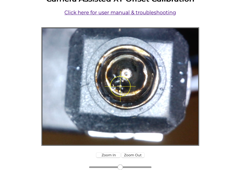
Been dusting off some maths knowledge today to try and more accurately position my print head over the top of the camera after auto aligning with the ball probe.

Firstly used a few captured nozzle probe and manually aligned readings, plus some measurements of the distance of the probe and camera from the servo pivot point to try and work out the XY coordinates of the servo pivot point.
With a bit of trial and error I found some numbers that worked

Then wrote this macro to calculate the camera position from ball probed UV coordinates - really please to see SIN/COS/ASIN/ACOS functions available...
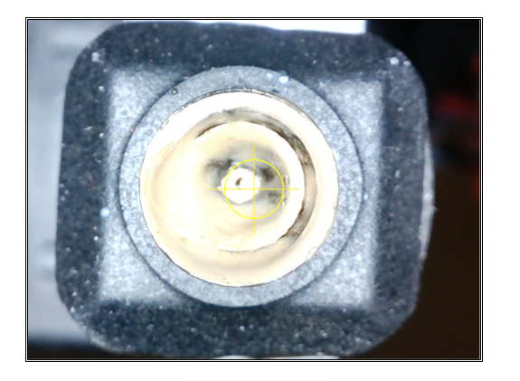
;cameraFromUV.g

M98 P"0:/macros/ParkXY.g"


;probe U 251.3187 offset U -13.6500092 probe V 202.1375 offset V 41.20003
;probe U 251.0562 offset U -14.2998352 probe V 199.4344 offset V 41.00005
;probe U 250.8687 offset U -14.7497253 probe V 197.4219 offset V 40.84999
;probe U 250.8938 offset U -14.6997528 probe V 197.5125 offset V 40.85002
;probe U 250.8000 offset U -15.0500336 probe V 196.2250 offset V 40.80002
;probe U 250.9875 offset U -14.4999847 probe V 198.0063 offset V 40.89999
;


;G1 U251.4 V202.8 F10000
var uPos = global.ballProbeU+14.5
var vPos = global.ballProbeV-40.9

var servoX = 427.9
var servoY = 188.3
var probePosRadius = 177
var cameraPosRadius = 165
var cameraOffsetAngle = 14

var probeAngle = degrees(asin((global.ballProbeV-var.servoY)/var.probePosRadius))

if var.probeAngle < 90
    set var.probeAngle = 180 - var.probeAngle

var cameraX = var.servoX + var.cameraPosRadius * cos(radians(var.probeAngle+var.cameraOffsetAngle))
var cameraY = var.servoY + var.cameraPosRadius * sin(radians(var.probeAngle+var.cameraOffsetAngle))


echo "U",global.ballProbeU,"V",global.ballProbeV,"angle",var.probeAngle,"cX",var.cameraX,"cY",var.cameraY

if var.cameraX > 200 && var.cameraX < 300 && var.cameraY > 140 && var.cameraY < 200
    set var.uPos = var.cameraX
    set var.vPos = var.cameraY
else
    abort "cameraFromUV.g - suspect camera calculations"


if exists(global.savedU) == false
    global savedU = -1
    global savedV = -1

set global.savedU = var.uPos
set global.savedV = var.vPos


G1 U{var.uPos} V{var.vPos}  F10000

if exists(global.servo5Off) && global.servo5Off > 0
    set global.servo5Off = state.upTime + 120
if exists(global.magnetOff) && global.magnetOff > 0
    set global.magnetOff = state.upTime + 120
results pretty good - all photos are auto alignment and direct move to the camera
Notice the benefits of a camera over a ball probe in first photo - where the ball probe misaligned due to dirty nozzle.

UV
XY after cleaning

-
Sub second tool change demo.

-
@dwuk3d As long as the belts along the crossbeam aren't aligned properly you won't see accurate positions anywhere else on the bed.
But it's good to have the theory behind alignement solved. -
@o_lampe yes - probably need to properly align belts in next stage.
I'm also thinking of trying the probe at some different angles to see whether the alignments of the two gantries are the same with the probe at different places on the bed.
I quite like the look of the new BambuLab H2D special alignment print bed - using camera's on the print head to read tiny qr codes at pre determined places.
-
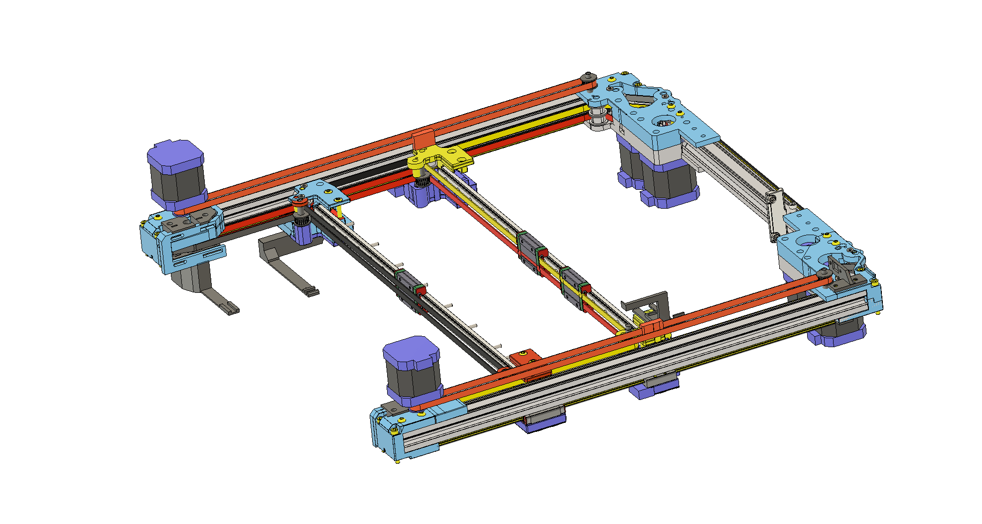
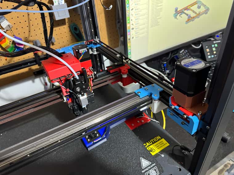
Made a start on IDEX motor and pulley mount (above side gantry supports) - will hold the idler at the back from the top took and introduce a tensioning system.
Zip Ties just temporary until I have the new top of gantry belt coupling.
Will have a mirror of the motor mount and idler on the other side.
The new motors at the front on each side will take over the Y axis movement - with the existing X & Y used for one print head each on the rear gantry.
Also tidied up extruders a bit and created top cover for 1LC boards.

-
starting to think about my occasionally moving bed phase.
My original idea for an occasionally moving bed was to allow for the printing of longer thin objects.
But my experience of even printing fairly small object is that the area where both print heads can access without hitting each other is quite restricted - so I think even the current size 350x350 bed moving maybe only 150mm would give some quite big benefits with very little overhang outside of the main printer body.
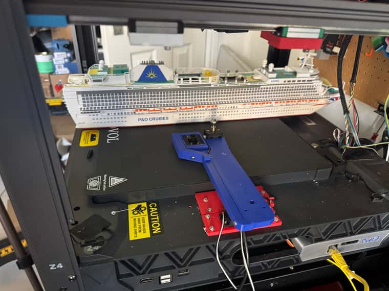
I think though that I want to go to 350 x 500 or even 350 x 550 - so that when parked the bed still fits nicely within the main printer size - but also allows for ships like the one shown (at 1:500 scale model) to be printed in one go.
Another interesting concept when thinking about ships - is the bow - which overhangs - that doesn't need a build plate under it - so would be an interesting concept having a print going completely beyond the build surface.