Core XY movement issues
-
@deckingman
just finished swapping the steppers. I left the M92 the same. Before I swapped the motors, I did a G1 x250, the head did not move in the Y. I just did a I did a G1 x250 and Y did not move. So the same as before.
RJ -
@phaedrux
Thanks. At least that is some progress.
RJ -
I looked at
https://forum.duet3d.com/topic/4958/y-axis-moves-when-only-x-is-commanded/10
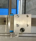
again, where you made some pictures of your printer.I wondered whether the linear X guide is connected stable enough (I mean the linear guide in the middle, connected to hotend). I had a problem at my own CoreXY printer that moving by hand was ok on one side, but not at the other. It blocked totally because the connection bends a bit and the one linear guide blocks.
In your picture the one side is connected by a screw, on the other by a linear mgn guide which is very good to level temperature effects. But the disctance between linear guide and aluminium cage seems to be different at both sides and the linear guide alone seems to be too little support (one or two screws on one side). The difference at the mgn side seems to be less than the other side. On the mgn side the belts are not in the middle in respect to the cage.
The difference leads to different Y positions at the both sides and leads to become stuck because the pulleys have different positions.
-
At this side
the left belt side is very strange. It seems to go around a shaft and so a nonlinear movement is introduced.
-
@fxxtoo I don't think it has anything to do with your printer's problem, but what @JoergS5 is pointing out is that the X axis bearing block at the P2 pulley assembly appears to be thicker than the spacer at the end of the X axis rail at the P1 pulley assembly. When I built my printer, I made the spacer to match the thickness of the bearing block. That keeps the P1 and P2 pulleys at exactly the same Y position when the rails are square.
It shouldn't make any difference as long as you ensure that the X and Y guide rails are square when you tension the belts. In other words, don't use the pulley position along Y to determine if it's square, use the guide rails as the reference.
@JoergS5 The left side belt comes off the pulley in the block and goes directly to the extruder carriage. You're seeing parallax - there's no shaft- the top of the pulley assembly has 4 tool access holes for screwing the assembly to the Y axis bearing block..
-
@fxxtoo said in Core XY movement issues:
@deckingman
just finished swapping the steppers. I left the M92 the same. Before I swapped the motors, I did a G1 x250, the head did not move in the Y. I just did a I did a G1 x250 and Y did not move. So the same as before.
RJWhat? I thought you were saying that when you moved in X, there was movement in Y as well. Now you are saying there isn't. Totally confused now by what the problem actually is.
-
@mrehorstdmd Thank you for explaining the holes. It's difficult to analyze from a photo.
The reason for this all is still mysterious, we should place bets. I heard the British like to bet.
-
@deckingman I changed the settings in the M92 from X320 Y319 and the movement stopped and appears to be working normally. I did this based upon the 2nd link I posted as that was a similar problem as mine.
I left the M92 setting the same,adjusted so there was no movement in the Y when X was moved. I still have it set up with the motors swapped. I can set the M92 back to x320 y320 and try it both ways. I was going to take the board out of the enclosure to really examine the boardto see what I find. After some of the post I have found about board issues and pictures I have found, missing or bad solder joints, etc. -
@fxxtoo
I am looking at the belt alignment. Are they the same on both sides? Optimal would be to run them inline and not in an angle like you do as this might influence the movement if not mirrored perfectly. Or am I watching something the wrong wayValkyrie DIY High Temp 3D Printer
R&D - Engineering Designer - Viking 3D Printers
https://vkingprinter.com/ -
@joergs5 I thought I made the distance from the pulley blocks on the Y axis to the rail on the X axis were the same on both sides. I will check that when I get off work. Thanks for bringing that up!
rj -
@fxxtoo Ah I see. Sorry I forgot that you had set the X and Y steps per mm differently as a work around. I guess I kind of assumed that you would use the same steps per mm on both X and Y for the purpose of that test. No matter. The fact that you get the same movement with the motors physically swapped at least eliminates the motors as a cause of the problem.
-
@pro3d
I think you are talking about the belt that goes around the motor pulley and back around to the extruder mount.
This is the way I did them.

-
Can you confirm that you have physically swapped the motor connectors between A and B motors. If so what happened with the issue?
-
@t3p3tony
Hi Tony, Thanks for posting. I would like to be sure about what you are asking me to do.
At this time I have done the testing as per the docs.
G91 G1 S2 X100 F3000 ; MOVES X+ AND Y+ , as it should
G91 G1 S2 Y100 F3000 ; MOVES X+ AND Y- .
Doing a G90 G1 X100 causes Y to move about 3 mm in the + dir
Doing a G90 G1 Y100 causes X to move about 3 mm in the + dir
After changing * and still at M92 X320 Y319 doing the above,
the X only moves when the same command is sent, same as when the Y command is sent.
I have physically swapped the A and B motors, And with the M92 X320 Y319, it behaves normally. With M92 320 Y320, it reverts to Y moving a bit when moving X and vice versa. But the new A motor went to the A connector. So that is where my question comes in.
I can tell you what it will do, with the connectors in the correct places, a G90 G1 X100 command will cause X to move 100 to the plus and the Y to move ~3mm to the plus. The same with a G1 Y100.
If I swap the connectors and run it twon't that change the directions of the motors? Will I have to change those settings as well?
Should I set the steps back to M92 X320 Y320 first? Then run G1 X100 and then G1 Y100. Then swap the connectors on the board and then run the same commands, to see what it does before and after? Sorry if I seem a bit flustered, as I am.
RJ -
@fxxtoo I think what you'll need to do to accomplish what Tony is asking is to swap the motor connectors, then re-map the drives. So you'll need to add this to the start of your drive section in config.g
M584 X1 Y0
Make sure you put it at the start of the drive section. Your motor directions are all the same so they should not be affected.
So you'll physically swap the stepper connectors on the board so that what was X is now connected to Y and what was Y is now connected to X. Then by adding that line, it'll swap the drivers so you should end up with exactly the same movement. If you get a different result, then it would indicate a faulty driver.
So to be sure, set the steps per mm the same for both axes. Do the long x move first and note any Y movement, then swap the cables and re-map the drives, then repeat.
-
@deckingman
Thanks. I think we are getting closer.. Should I go back to M92 X320 Y320 for this test? -
@fxxtoo
After Checking Ians points, another idea:The pulleys, do they grind anywhere at each other? This would explain X movement when you move Y and vice versa. They must be separated by washers each and may not effect each other.
-
@fxxtoo said in Core XY movement issues:
@deckingman
Thanks. I think we are getting closer.. Should I go back to M92 X320 Y320 for this test?Yes please
-
@joergs5
No, there are shims to space them all out the same distances to keep them aligned for the belts.
thanks,
RJ -
@t3p3tony , @deckingman
So I got to do the swap test of A & B connectors. I set M92 X320 Y320 and with the cables in the correct position, homed and then did G1 X200, Y moved along with X moving about 3mm. Powered down, swapped the cables , M92 the same and tried the G1 X200 and got the same results. Just for giggles I did M92 X320 Y319 and Did not get the movement in the Y axis when X was moving. It appears to move about 3mm per 100mm move on the opposite axis. I remapped using M584 X1 Y0.
I contacted Filastruder about this and said they were forwarding it to Duet.
What is the verdict?
thanks,
RJ