Duet 3 no power coming to bed.
-
Not sure what could be happening, and there doesn't seem to be much info on this subject, so I'm looking for solutions. I'm running a Duet 3 board, off a 12v 29.7a PSU. I have both a raspberry pi, and LCD monitor hooked to my board, in order to get wifi capabilities. Everything is rated for 12v, my thermistors are reading fine, My hot end even runs fine. I've tried different heat beds, the same model, and different wiring configs. My wiring to the bed is as recommended by the guide via OUT0. Am drawing too much power from the other things plugged in? Do i need to bump up my power supply?
FYI I'm upgrading from a duet WIFI, with all the same equipment, that worked fine beforehand, and honestly, this upgrade is starting to become a freaking headache
here is my config file.
; Configuration file for Duet 3 (firmware version 3)
; executed by the firmware on start-up
;
; generated by RepRapFirmware Configuration Tool v3.2.0 on Sun Jan 03 2021 21:41:01 GMT-0500 (Eastern Standard Time); General preferences
G90 ; send absolute coordinates...
M83 ; ...but relative extruder moves
M550 P"Duet 3" ; set printer name
M665 R144 L290 B140 H250 ; Set delta radius, diagonal rod length, printable radius and homed height
M666 X0 Y0 Z0 ; put your endstop adjustments here, or let auto calibration find them; Drives
M569 P0.0 S1 ; physical drive 0.0 goes forwards
M569 P0.1 S1 ; physical drive 0.1 goes forwards
M569 P0.2 S1 ; physical drive 0.2 goes forwards
M569 P0.3 S1 ; physical drive 0.3 goes forwards
M584 X0.0 Y0.1 Z0.2 E0.3 ; set drive mapping
M350 X16 Y16 Z16 E16 I1 ; configure microstepping with interpolation
M92 X160.00 Y160.00 Z160.00 E833.16 ; set steps per mm
M566 X120000.00 Y120000.00 Z120000.00 E120000.00 ; set maximum instantaneous speed changes (mm/min)
M203 X1080000.00 Y1080000.00 Z1080000.00 E1080000.00 ; set maximum speeds (mm/min)
M201 X4200.00 Y4200.00 Z4200.00 E5000.00 ; set accelerations (mm/s^2)
M906 X1200 Y1200 Z1200 E1200 I30 ; set motor currents (mA) and motor idle factor in per cent
M84 S30 ; Set idle timeout; Axis Limits
M208 Z-20 S1 ; set minimum Z; Endstops
M574 X2 S1 P"io0.in" ; configure active-high endstop for high end on X via pin io0.in
M574 Y2 S1 P"io1.in" ; configure active-high endstop for high end on Y via pin io1.in
M574 Z2 S1 P"io2.in" ; configure active-high endstop for high end on Z via pin io2.in; Z-Probe
M558 P0 H5 F120 T6000 ; disable Z probe but set dive height, probe speed and travel speed
M557 R85 S20 ; define mesh grid; Heaters
M308 S0 P"temp1" Y"thermistor" T100000 B4138 ; configure sensor 0 as thermistor on pin temp1
M950 H0 C"out0" T0 ; create bed heater output on out0 and map it to sensor 0
M307 H0 B0 S1.00 ; disable bang-bang mode for the bed heater and set PWM limit
M140 H0 ; map heated bed to heater 0
M143 H0 S120 ; set temperature limit for heater 0 to 120C
M308 S1 P"temp0" Y"thermistor" T100000 B4138 ; configure sensor 1 as thermistor on pin temp0
M950 H1 C"out1" T1 ; create nozzle heater output on out1 and map it to sensor 1
M307 H1 B0 S1.00 ; disable bang-bang mode for heater and set PWM limit
M143 H1 S280 ; set temperature limit for heater 1 to 280C; Fans
M950 F0 C"out5" Q500 ; create fan 0 on pin out5 and set its frequency
M106 P0 S1 H-1 ; set fan 0 value. Thermostatic control is turned off
M950 F1 C"out4" Q500 ; create fan 1 on pin out4 and set its frequency
M106 P1 S1 H1 T45 ; set fan 1 value. Thermostatic control is turned on; Tools
M563 P0 D0 H1 F0 ; define tool 0
G10 P0 X0 Y0 Z0 ; set tool 0 axis offsets
G10 P0 R0 S0 ; set initial tool 0 active and standby temperatures to 0C; Custom settings are not defined
; Miscellaneous
M911 S10 R11 P"M913 X0 Y0 G91 M83 G1 Z3 E-5 F1000" ; set voltage thresholds and actions to run on power loss -
Have you provided power to the separate OUT0 power in terminals?
Duet WiFi hardware designer and firmware engineer
Please do not ask me for Duet support via PM or email, use the forum
http://www.escher3d.com, https://miscsolutions.wordpress.com -
6-way barrier strip: two pins for main VIN and GND; two pins for the VIN and GND supply for the OUT_0 terminals; and positive and negative OUT_0 terminals. OUT_0 is intended to drive a bed heater. The ground side of OUT_0 is switched by the mosfet and the positive side is protected by a 15A fuse.
-
@dc42 I'm not going to pretend like I know what that means, but the guide only stated to run power from the PSU to the board via the "Power in" and then to run power from the board to the bed via "Out0" so I did that.
Here is a photo of my connections.
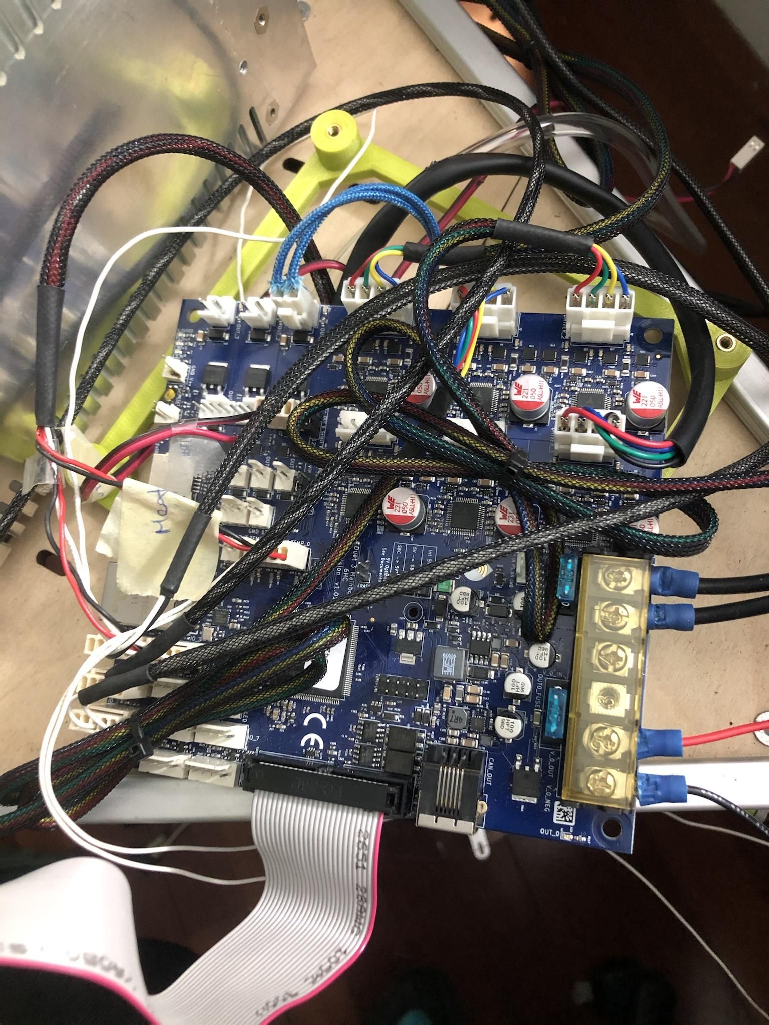
-
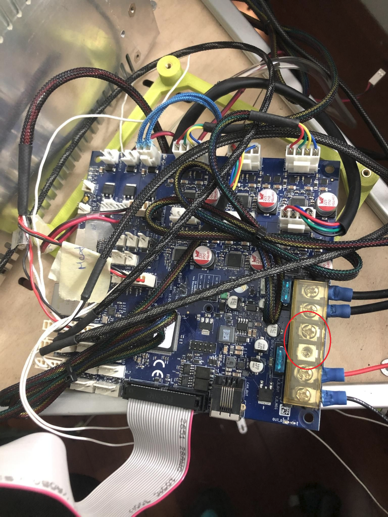
@eddygara Issue is obvious - no power connected to OUT0_POWER_IN terminals (the two screw terminals between power in and OUT0).
Take a look here: https://duet3d.dozuki.com/Wiki/Duet_3_Mainboard_6HC_Wiring_Diagram -
@BoA But it doesn't mention anything of this on the guide. And honestly nowhere in that link does it state to add power to that terminal to power the bed, I hope you can see why this is confusing for me.
From the guide-------------------------------
Low voltage bed heater driven directly from the Duet
Duets provide a terminal block for connecting a bed heater. The voltage supplied to the bed heater is the voltage you apply to the VIN terminals from your power supply. The maximum current you can safely draw depends on the Duet version.
Important! Do not "tin" the ends of the wires. The heat generated by high bed currents can cause the wires to creep, which in turn makes them loose in the terminal block. So you should re-check the bed heater terminal block screws for tightness regularly, especially during the first few days of use. This is especially important if you use stranded-core wire without crimping bootlace ferrules on the ends.
Duet 3 Mainboard 6HCThe Duet 3 Mainboard 6HC is safe up to 18A heater current on OUT0 in a normally ventilated environment.
-
@eddygara This seems to be true in case of Duet Maestro, Duet2 and Duet3 Mini, but Duet3 has separate power input for OUT0. Where is this guide?
-
@BoA So what exactly me I connecting to that terminal and from where?
-
@eddygara from your PSU to the two connectors next to the other power inputs. Make sure the polarity is right
-
@eddygara Power for OUT should be connected here:
-
@eddygara BTW - the wires connected to OUT0 seem to bery thin. Are You certain they can handle the current? at 12V there might be a significant current flowing.
-
@BoA Ok just to make sure so i dont blow up my board, I already have the board connected from the psu via the "power in" your telling me to run another connection from the PSU right next to the PSU to Board line. In order to get power to the Bed?
-
@eddygara Exactly. Keep in mind that "power in" itself can be loaded with a high current 3 heaters 6A each, few fan outputs 2.5A and... steppers drivers... and some other stuff. So separate heatbed power input is for some flexibility in PSU setup and to avoid overloading connectors.
-
@BoA Thanks a lot man, I wish this guide wasn't so jumbled around to find this info, the people like you make this product worth it to use.
-
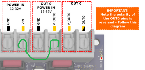
If you want to power both the mainboard and the bed from the same power supply, add a jumper like this.
(Wire in green)You also may have to wire a jumper from GND to GND.
(This I don't know. I think someone will answer here.) -
@alankilian Ok this goes against what @boa just said..
-
Right. I got my information from here:
https://duet3d.dozuki.com/Wiki/Duet_3_Mainboard_6HC_Wiring_Diagram -
@eddygara How? It shows exactly what I said. Connect power from PSU to this input.
-
@eddygara said in Duet 3 no power coming to bed.:
your telling me to run another connection from the PSU right next to the PSU to Board line
I think this was interpeted to mean jumper Vin to the GND screw terminal "right next to the PSU to Board line"
-
@BoA You told me to run 2 separate cables from the PSU directly to the board, you didn't say anything about jumping connections, from "Power in" to "Out0" in order to get power from the same PSU