Duet3D Logo Duet3D
    • Tags
    • Documentation
    • Order
    • Register
    • Login

    Creality CR Touch Sensor

    Scheduled Pinned Locked Moved Unsolved
    Duet Hardware and wiring
    4
    26
    6.3k
    Loading More Posts
    • Oldest to Newest
    • Newest to Oldest
    • Most Votes
    Reply
    • Reply as topic
    Log in to reply
    This topic has been deleted. Only users with topic management privileges can see it.
    • Wladekczundefined
      Wladekcz
      last edited by

      Yes, I have this datasheet, it still doesn't change anything.

      Władekcz

      1 Reply Last reply Reply Quote 0
      • rjenkinsgbundefined
        rjenkinsgb
        last edited by rjenkinsgb

        OK, confusion! The mention of BL Touch in the original question made it appear to the the Antclabs one.

        They appear to both use exactly the same connections & same newer colour cable as my BL version - but do have some differences in the control signal, unfortunately, as the articles mention different software/firmware addons.

        https://www.creality3dofficial.com/products/creality-bl-touch

        https://www.creality3dofficial.com/products/creality-cr-touch

        Edit - looking through the installation docs for the new CR touch, it still uses the BL Touch firmware - so presumably it does use the same signals?? Possibly just a custom BL Touch version for them?

        Robert J.

        Printers: Overlord pro, Kossel XL+ with Duet 6HC and "Frankentron", TronXY X5SA Pro converted to E3D toolchange with Duet 6HC and 1LC toolboards.

        1 Reply Last reply Reply Quote 0
        • Wladekczundefined
          Wladekcz
          last edited by

          I am sending photos and files: configuration, M122.

          config_g.txt
          config-override _g.txt
          M122.txt
          sensor CR.jpg
          sensor CR-QR.jpg
          kabel-1.jpg
          kabel2.jpg
          kabel-3.jpg

          Władekcz

          1 Reply Last reply Reply Quote 0
          • rjenkinsgbundefined
            rjenkinsgb
            last edited by

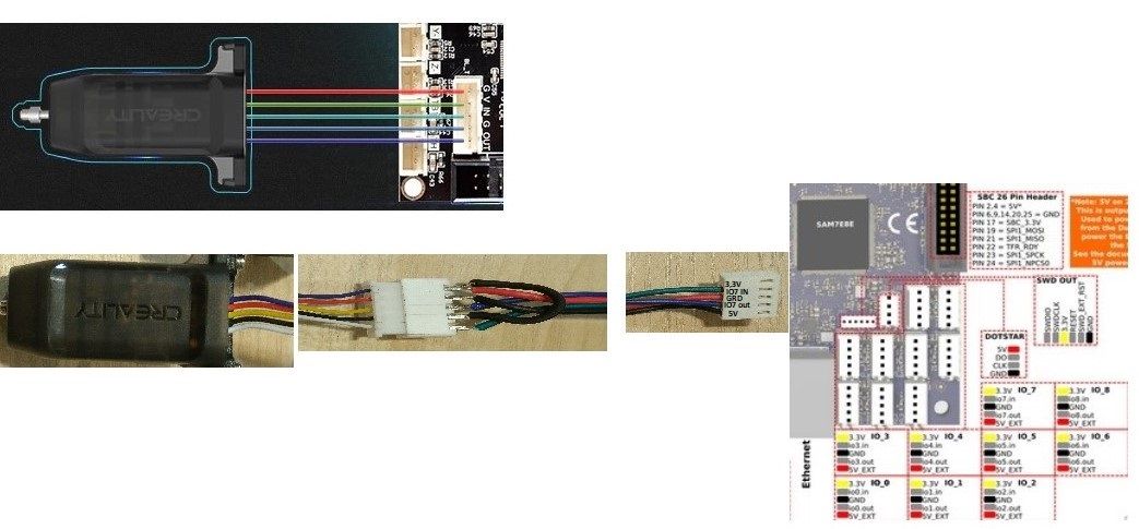
            Where you show the plug and socket linking the two cables, the wire sequence from the probe is reversed.

            I believe it should be, without rearranging the plug at the Duet board end:

            Probe white and red to duet red.
            Probe black to duet black
            Probe yellow to duet blue
            Probe blue to duet green

            Robert J.

            Printers: Overlord pro, Kossel XL+ with Duet 6HC and "Frankentron", TronXY X5SA Pro converted to E3D toolchange with Duet 6HC and 1LC toolboards.

            Wladekczundefined 1 Reply Last reply Reply Quote 0
            • Wladekczundefined
              Wladekcz @rjenkinsgb
              last edited by

              @rjenkinsgb creality.jpg

              Yes you are right, this is another attempt, in the previous version "IN" and "OUT" were swapped and the effect was the same. I am thinking about the resistor but I do not know where to connect it.

              Władekcz

              1 Reply Last reply Reply Quote 0
              • rjenkinsgbundefined
                rjenkinsgb
                last edited by

                The power (+5v) and ground are still reversed!

                Change it to match the connections I put in my last post.

                Robert J.

                Printers: Overlord pro, Kossel XL+ with Duet 6HC and "Frankentron", TronXY X5SA Pro converted to E3D toolchange with Duet 6HC and 1LC toolboards.

                Wladekczundefined 1 Reply Last reply Reply Quote 0
                • Wladekczundefined
                  Wladekcz @rjenkinsgb
                  last edited by

                  @rjenkinsgb Unfortunately, the reversal of 5+ and the ground did not give the expected effect. The core was not ejected. M401 and M402 do not work. Robert please check config_g.
                  It is like this
                  "; Probe Z
                  M950 S0 C "io7.out"
                  M558 P9 C "! Io7.in" H5 F120 T6000
                  G31 P500 X30 Y30 Z2.5
                  M557 X30: 280 Y30: 280 S30
                  Shouldn't it be like this:
                  M950 S0 C "io7.out"
                  M558 P9 C "^! Io7.in" H5 F120 T6000
                  G31 P500 X30 Y30 Z2.5
                  M557 X30: 280 Y30: 280 S30

                  Władekcz

                  T3P3Tonyundefined 1 Reply Last reply Reply Quote 0
                  • T3P3Tonyundefined
                    T3P3Tony administrators @Wladekcz
                    last edited by

                    @wladekcz said in Creality CR Touch Sensor:

                    M558 P9 C "^! Io7.in" H5 F120 T6000

                    no you should not have the pullup (^) on the input pin. Also if its the same as a normal BL touch from a signal perspective then the signal inversion (!) is also not needed so try:

                    M950 S0 C "io7.out"
                    M558 P9 C "Io7.in" H5 F120 T6000
                    

                    www.duet3d.com

                    Wladekczundefined 1 Reply Last reply Reply Quote 0
                    • Wladekczundefined
                      Wladekcz @T3P3Tony
                      last edited by Wladekcz

                      @t3p3tony I connected the sensor cable directly to the connector on the Duet3. After connecting the power, the sensor turned blue.

                      IMG_20211103_144048.jpg

                      Still not working properly. I measured the tensions between the cables. Between the ground and 5+ "4.9V". Between ground and white and yellow "4.88V". I read on the wiki that out and in only tolerate 3.3V. Do you have any suggestions.

                      IMG_20211103_144159.jpg

                      Władekcz

                      1 Reply Last reply Reply Quote 0
                      • rjenkinsgbundefined
                        rjenkinsgb
                        last edited by

                        This is my BLTouch config:

                        ; Z-Probe
                        M950 S0 C"io7.out"                           ; create servo pin 0 for BLTouch
                        M558 P9 C"^io7.in" H5 F100 T6000             ; set Z probe type to bltouch and the dive height + speeds
                        G31 P500 X-46 Y4.5 Z2.840                    ; set Z probe trig value, offset (from TC face centre)+ trigger height
                        M557 X0:240 Y10:270 S20                      ; define mesh grid
                        

                        You need to adjust the offsets and grid to suit your machine.

                        It is unfortunately possible that it may have been damaged by having the positive and negative power reversed.

                        Robert J.

                        Printers: Overlord pro, Kossel XL+ with Duet 6HC and "Frankentron", TronXY X5SA Pro converted to E3D toolchange with Duet 6HC and 1LC toolboards.

                        1 Reply Last reply Reply Quote 0
                        • rjenkinsgbundefined
                          rjenkinsgb
                          last edited by

                          From that photo, you still have some wires wrong.

                          With the Duet connector as shown above:

                          The first pin on the left should be just black (+5V)
                          Second pin: Yellow; OK (Out from Duet, In to probe)..
                          Third pin: Red and White; (Grounds).
                          Fourth pin: Blue (Out of probe, In on duet).
                          Fifth pin: No connection; OK.

                          Robert J.

                          Printers: Overlord pro, Kossel XL+ with Duet 6HC and "Frankentron", TronXY X5SA Pro converted to E3D toolchange with Duet 6HC and 1LC toolboards.

                          Wladekczundefined 1 Reply Last reply Reply Quote 0
                          • Wladekczundefined
                            Wladekcz @rjenkinsgb
                            last edited by

                            @rjenkinsgb This was the case in the previous version and you suggested that I change what I did. Take a look at the previous photos. So I have to return to the original version. Red - 5+, yellow - in, black with blue - ground, white - out, empty - 3.3V

                            Władekcz

                            1 Reply Last reply Reply Quote 0
                            • Wladekczundefined
                              Wladekcz
                              last edited by

                              @rjenkinsgb said in Creality CR Touch Sensor:
                              I connected according to your last instruction. The sensor glows blue, the core is hidden. Will not respond to M401 / M402. Without the "!" With Probe 1000. In your configuration "M558 P9 C" ^ io7.in "H5 F100 T6000" appears "^" And I don't know if it should be or not

                              IMG_20211104_074430.jpg
                              Bez tytułu.gif
                              M122.txt

                              config,g.txt

                              Władekcz

                              1 Reply Last reply Reply Quote 0
                              • Wladekczundefined
                                Wladekcz
                                last edited by

                                I measured the voltage on the sensor:
                                red - yellow 0.115Volt
                                red - blue 1.583V
                                red - black 4.905V
                                black - yellow 0.115V
                                black - blue 1.583V

                                Władekcz

                                1 Reply Last reply Reply Quote 0
                                • rjenkinsgbundefined
                                  rjenkinsgb
                                  last edited by rjenkinsgb

                                  OK; that wiring is now exactly the same as my fully working probe + 6HC setup.
                                  I have just done a continuity check from the probe to the board to 100% confirm that is how it is connected.

                                  The Crealty diagram shows the CL version uses exactly the same electrical wiring as the BL one.

                                  So, either the Crealty documentation is wrong re. the probe control values etc. and it needs different parameters in the config file compared to a BL-Touch, or the probe has been damaged by reverse supply connections earlier on..

                                  Robert J.

                                  Printers: Overlord pro, Kossel XL+ with Duet 6HC and "Frankentron", TronXY X5SA Pro converted to E3D toolchange with Duet 6HC and 1LC toolboards.

                                  1 Reply Last reply Reply Quote 0
                                  • ZeDCundefined ZeDC referenced this topic
                                  • wayneosdiasundefined
                                    wayneosdias
                                    last edited by

                                    @Wladekcz said in Creality CR Touch Sensor:

                                    G31 P500 X30 Y30 Z2.5

                                    I know this old but I just went thru same issue; Min 5+ and CR Touch
                                    Probe would deploy/retract and trigger, but not reset post probing. In DWC the reported value was 1000.
                                    I changed Duet configurator supplied G31;

                                    G31 P500 X30 Y30 Z2.5
                                    

                                    to

                                    G31 P1000 X30 Y30 Z2.5
                                    

                                    It all seems to work fine now. Given I never had a miss wire so there still be a HW issue w that.

                                    1 Reply Last reply Reply Quote 0
                                    • Flynbrdundefined Flynbrd referenced this topic
                                    • First post
                                      Last post
                                    Unless otherwise noted, all forum content is licensed under CC-BY-SA