Connecting stepper motor encoders to closed loop drivers
-
I am purchasing CL57T closed loop drivers how will i go about connecting the stepper motors encoders to them?
-
-
Does the process consist of connecting the encoders to the drivers and they will begin reading or do I need to configure something else to get a read from the encoders?
-
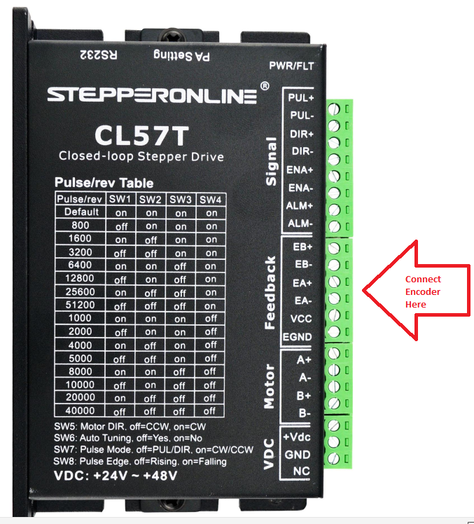
@v-a-m-p-printing-snproj Your Steppers should have a cable coming off the cap at the back as a seperate connection with 6 pins. Those will be your encoder hook up wires. you need to find the manual for the steppers/encoders to know which wires are which for EA+/-, EB+/-, VCC, and EGND. If connected correctly they should start read automatically. The ones that I have did anyway. It is possible that you will need to program the driver for the encoders pulse count and direction, but you might need the programming cable for that.
-
@baird1fa Okay thanks. Also my old drivers do not have a connection slot for the Alarm, Brake, or Com-. Can I leave these connections empty or do they need to be connected?
-
@v-a-m-p-printing-snproj said in Connecting stepper motor encoders to closed loop drivers:
Does the process consist of connecting the encoders to the drivers and they will begin reading or do I need to configure something else to get a read from the encoders?
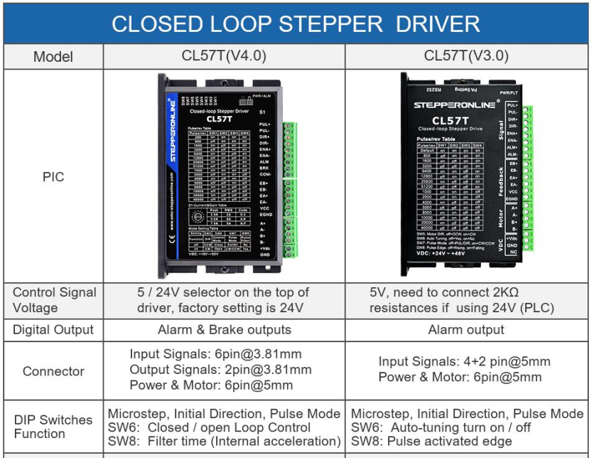
Some versions of CL57T have a switch to set open-loop vs. closed-loop mode and some do not.
-
-
@v-a-m-p-printing-snproj I purchased the v4.0
-
@v-a-m-p-printing-snproj OK, so SW6 controls the mode open-loop or closed-loop.
Connect it and go.
You will almost certainly need to download the correct tuning software from the link you posted and build or buy a communications cable.
You can hook it up and do some testing and if it doesn't perform the way you like you can get the communications software and start there.
-
@v-a-m-p-printing-snproj said in Connecting stepper motor encoders to closed loop drivers:
Also my old drivers do not have a connection slot for the Alarm, Brake, or Com-
You can leave those disconnected.
Can you post a diagram showing how you intend to wire the STEP and DIRECTION connections?
-
@alankilian  image url)
This is my current driver set up. My plan was to connect the encoders and then connect everything from this driver to the new one.
-
@v-a-m-p-printing-snproj OK, I didn't know you had external drivers working already and were just moving to closed-loop drivers.
Let us know how they perform PLEASE!
-
@v-a-m-p-printing-snproj The alarm and Brake will just be outputs that you can use to monitor for an error in the drive (like out of position) or to apply an external brake. The com will be for those outputs.
in my setup I have the alarm status being monitored to stop my controller from tying to continue when one drive has stalled out.
-
Thanks for the help! Ill let you know how they are working. Also what is the connection signal on the duet 2 ethernet? I have the option of setting the drivers to either 5v or 12v.
-
@v-a-m-p-printing-snproj Use 5v setting.
The Duet's 3.3 Volt output might work and if not, you should get the expansion board as described HERE.
-
@alankilian I got it figured out I already have the expansion board. I got the new drivers all connected along with the encoders, but when I try and home the print head it shoots off in the wrong direction and requires me to emergency stop the printer. Any idea why this could be?
-
@v-a-m-p-printing-snproj Your direction signal is the wrong-way around.
In the M569 configuration change the "S" value to say the motor goes the other way.
-
ALSO, first get everything workong in OPEN-LOOP mode by setting SW6 CLOSED.
After you get everything moving in the right directions, you can change to closed-loop mode and see if your encoder is wired backwards.
-
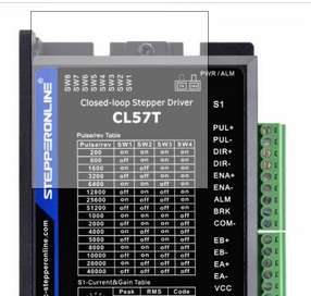
@alankilian Where will I find SW6?
-


