How Tough is a Scara Arm to Build?
-
After thinking on the Z-axis rail a bit more, I think something like this SBR16 rail from Zyltech is more appropriate, and really won't cost much more in the end: https://www.zyltech.com/zyltech-sbr16-linear-rail-set-bearing-blocks-pre-cut-lengths-300mm-2000mm/
I'm thinking two of these rails with a belted Z-axis going up the middle. I was thinking about how best to do this, and I really don't know what the weight of the assembly will be yet, but I'm curious if anyone has any thoughts on a geared nema 17 vs belts on a nema 23? It seems like the Voron design is trending towards a compound pulley system rather than geared stepper motors. I found a few examples where people were using these geared steppers for belted Z-axis's as well, is there a general consensus on what's better? The geared setup would be really quick and easy, but I'm not sure about back-drivability and backlash. A belted design would probably be lower backlash, but is more work and likely more expensive overall, but could also hit higher gear ratios and hold during a power-outage.
-
I assume you're talking about building this for a 3D printer...
Every hobbyist-built arm mechanism I have ever seen wobbles. That's going to translate to very poor print quality, unless you run it VERY slowly, in which case your jumbo print will take forever to finish. There's a reason industrial robots are built really big and heavy, and expensive.
I used a NEMA-23 motor with a 30:1 worm gear reducer to lift my printer's bed with two belts. It works fine and can handle the load my 300x300 bed assembly presents, but your 600x600 bed may be beyond the limit of what a single unit could lift. The gear box I used doesn't guarantee it can't be back-driven, but in my printer the load it sees is small enough that it won't move when power is cut. With a 600x600 bed you might have to go to a higher gear reduction ratio to lift and guarantee it won't back-drive.
-
Yes sorry, should have led with that. I was intended it to be a 3D printer using a 5 bar arrangement for added stiffness. I don't need it to move super fast, hopefully printing up to 100mm/s?
My idea was to raise and lower the arm assembly along the rail and keep the bed static on the floor. Depending on how heavy the whole gantry (end effector, scara arm and motors, and maybe the control board?) got to be, I would need to size the motors and gearing systems accordingly.
For now I think I should just try to get the scara arm running smoothly to the point where it would be usable as a printer. I got some 1" aluminum tubes and printed some connectors with bearings to play around with it. I'm just going to create a second SD card to drive the scara gantry to try it out. I'll stop worrying about the Z-axis for now until I've got a solid arm design figured out.
-
@michaelr123 check out what @koaldesigns built -- large scara, fully rotating joint at the distal arm end, pretty stable.
-
Here's what I came up with:
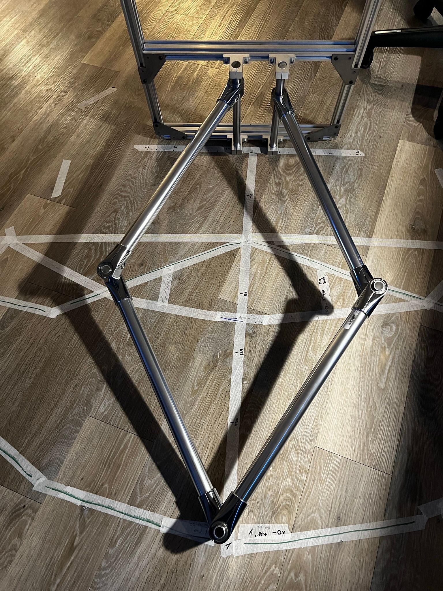
I have a have a 5 bar system mocked up using large ID bearings with aluminum tubes for shafts, and then then these aluminum clamps that go between the pipe and the bearings. The 32mm pipe and 32mm OD bearings pair really nicely. The joints are super stiff, zero friction, and it was pretty cheap to put this together. It'll be way more rigid than anything I could design and print. Here's a picture of the arm overlaying the working area taped out on the floor:
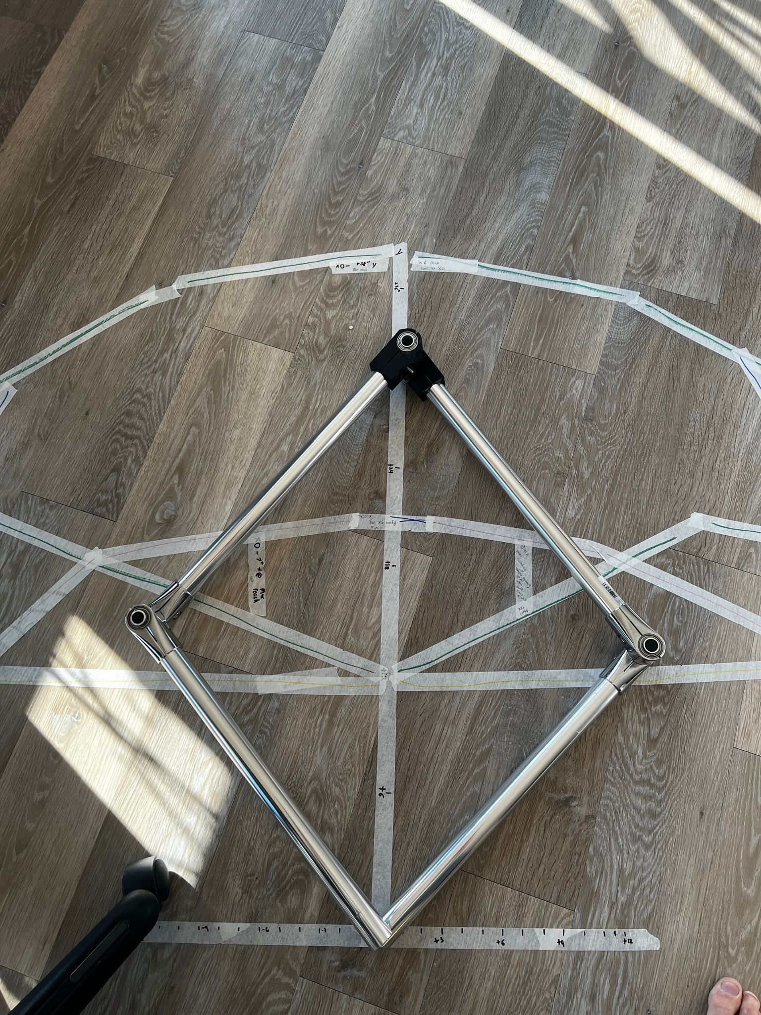
So far I'm really happy with how this clamp/ tube system for building aluminum frames is working out. I cut the 6ft of pipe I got into 4 pieces, so the sticks are 18" long each, which gives me a 21.25" arm length. Right now they're symmetric, but they certainly don't have to be.
I drew out the working area by just moving the arm around (faster than trying to figure out Geogebra or buying a matlab license). the Green / yellow region is what you get from having the two arm origin points being at (0,0). The red/blue region is what you get by moving them 6" apart in the X axis (12" total spread). Green being without an arm passing the X-axis for config X0, and yellow allowing a
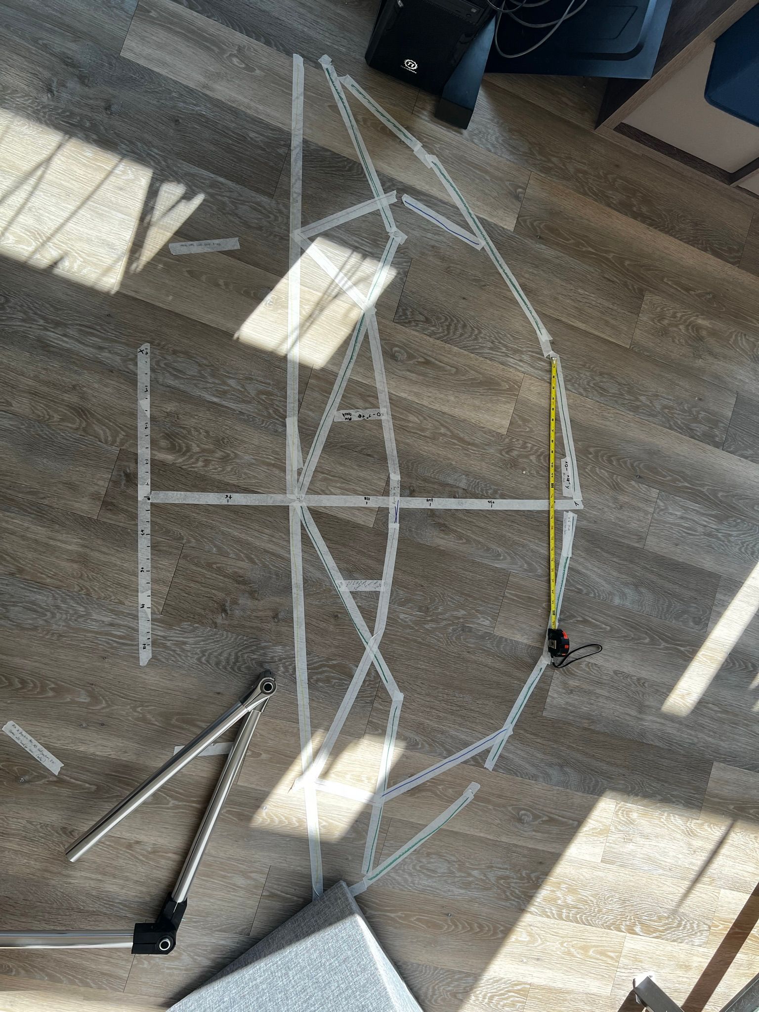
From what I can see, I get a 42"x18" working rectangular area, and a 24"x24" working square area from the X0 orientation as I'm calling it, and I lose quite a bit of working space if I start spreading out the 1st arm center points. I'm sure there's a stability gain and probably a resolution improvement with some more optimal angles, but I really wanted to be able to print a 24" square and also be able to print a 36" thinner piece. Any ideas or recommendations?
-
@michaelr123 hello, I would vary the distance of the two actuators, depending on the object you want to print. Then you'll have different possible print areas.
-
Update:
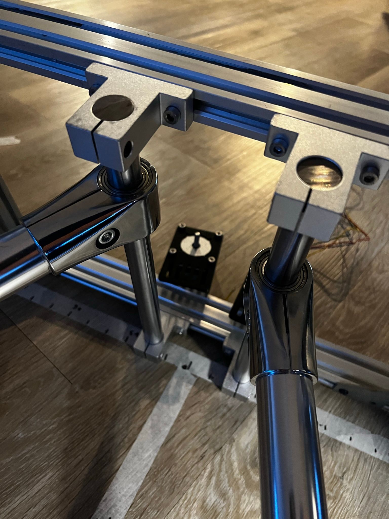
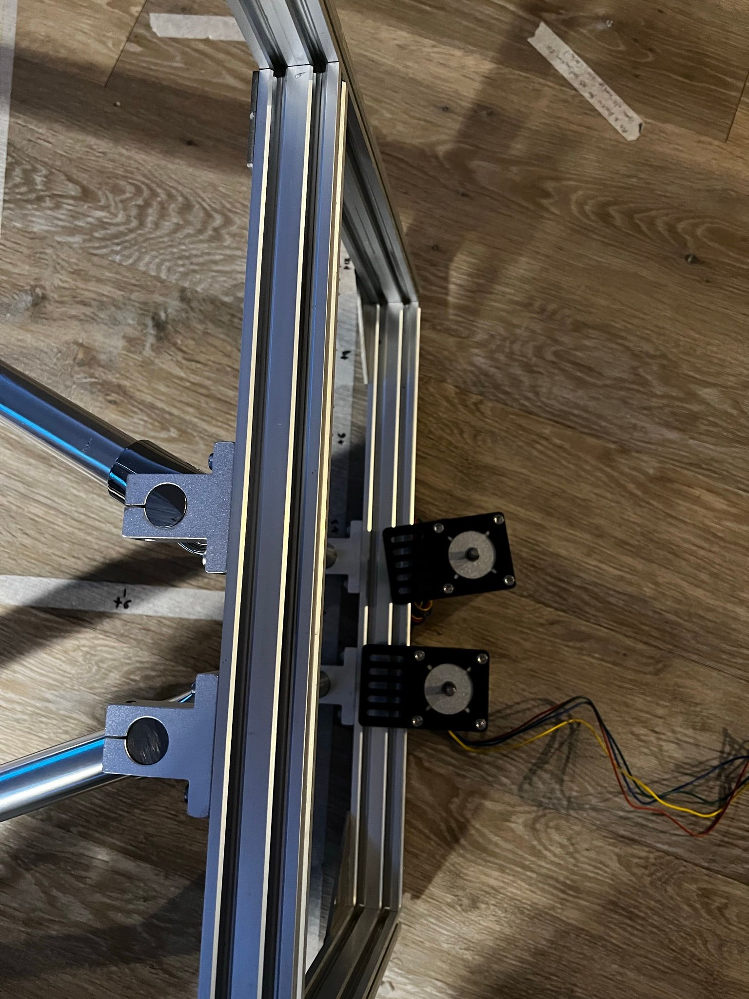
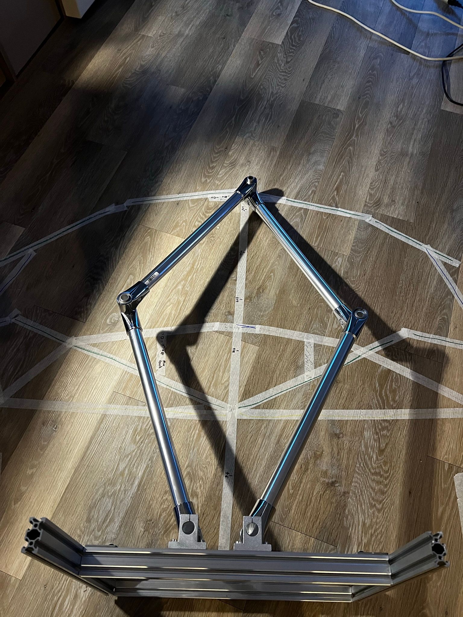
A lot of the parts came in and I was able to put together a frame for it with scrap 80/20. This is using 2 pivot points about 4in apart from each other. I need to figure out a configuration that leaves room for the gears and some range for the arms to move beyond the X axis in order to get the square printing area I want.
The single shaft design would be better for gear clearance, but the square frame I'm using still would interfere with the negative Y travel. I need some more hardware to show up so I can mount the motors and start experimenting with the actual drive. So far it still feels super rigid, zero slop, and only starts to deflect once you really push on it.
-
@michaelr123 I assume you have seen the work done by @JoergS5 and @bondus :
https://forum.duet3d.com/topic/11127/five-bar-parallel-scara/7?_=1648802688647
I saw @bondus 's machine at 3d meetup Sweden last weekend - printing away nicely - although at a bit smaller scale than what you are going for!
I am going to move this out of the CNC and into the Duet controlled machine category.
-
 undefined T3P3Tony moved this topic from CNC
-
I have build a five bar, it actually works very well. The double arms makes it very strong in the XY-plane, exactly what we need when FDM printing.
There are a few tricky parts building a five bar.You need to gear down your motors a lot to get enough steps/mm. And you need a gearbox with almost no backlash at all. The normal gearboxes you often find with steppers have way too much backlash. Ideally you would want a harmonic drive or possibly a cycloidal gearbox. I used gigantic pulleys (260t) and belts on my machine.
You have to be very precise on the length of the arms, and the angle of your homing sensors. A small error will result in warped parts. This is the similar to a delta printer, except that the firmware have amazing calibration algorithms to compensate for errors. The Five Bar firmware has no such features.
It can also be tricky to make the arm move in a perfectly flat plane. It's important to make sure all bearing rotate in the same plane. It is actually an over constrained system and if not built perfect there will be tensions in the arms.
A bed probe can compensate for small errors ofc. -
I made a little tool to help you plan the arm lengths:
https://github.com/bondus/5barscara/tree/master/JSFetch the git and open the html in a browser. It's a very crude little tool where you can experiment with arm lengths and work modes, it renders the possible work area and you can mouse in the work area to see the arms.