Duet3D Logo Duet3D
    • Tags
    • Documentation
    • Order
    • Register
    • Login

    M140 P0 S55 Error: Invalid password!

    Scheduled Pinned Locked Moved
    General Discussion
    5
    45
    1.6k
    Loading More Posts
    • Oldest to Newest
    • Newest to Oldest
    • Most Votes
    Reply
    • Reply as topic
    Log in to reply
    This topic has been deleted. Only users with topic management privileges can see it.
    • Phaedruxundefined
      Phaedrux Moderator
      last edited by

      No, the M552 commands only work in standalone mode when not using the Pi. You'd have to manage the networking settings on the pi itself.

      Z-Bot CoreXY Build | Thingiverse Profile

      jay_s_ukundefined 1 Reply Last reply Reply Quote 0
      • jay_s_ukundefined
        jay_s_uk @Phaedrux
        last edited by jay_s_uk

        @Phaedrux m552 etc work if using the duetpimanager I think
        Edit: they are usable. See here for info https://github.com/Duet3D/DuetSoftwareFramework/tree/v3.3-dev/src/DuetPiManagementPlugin

        Owns various duet boards and is the main wiki maintainer for the Teamgloomy LPC/STM32 port of RRF. Assume I'm running whatever the latest beta/stable build is

        Dizzwoldundefined 1 Reply Last reply Reply Quote 1
        • Dizzwoldundefined
          Dizzwold @jay_s_uk
          last edited by

          @jay_s_uk @Phaedrux

          Thank you your replies and help.

          I've disabled wifi with;
          sudo apt update
          sudo apt full-upgrade
          sudo apt install rfkill
          sudo rfkill block wifi

          Probe sensor led is detecting every time, but Duet/Pi in DWC is still missing probe points?

          Is this an SD card swap now, the feed rate of the probe is 120, so it's not going particularly fast?

          jay_s_ukundefined chrishammundefined 2 Replies Last reply Reply Quote 0
          • jay_s_ukundefined
            jay_s_uk @Dizzwold
            last edited by

            @Dizzwold what do you mean its still missing probe points? does it come up with anything in DWC?

            Owns various duet boards and is the main wiki maintainer for the Teamgloomy LPC/STM32 port of RRF. Assume I'm running whatever the latest beta/stable build is

            Dizzwoldundefined 1 Reply Last reply Reply Quote 0
            • chrishammundefined
              chrishamm administrators @Dizzwold
              last edited by

              @Dizzwold Those network errors aren't pretty but they should not affect the code being run on the Pi/Duet. These messages can only show up if the connection between Duet and your device is interrupted, but it's hard to say why exactly they occur. It might be a driver issue, but that is hard to tell. Do the same error messages show up on another device, e.g. on a smartphone or tablet?

              Duet software engineer

              1 Reply Last reply Reply Quote 0
              • Dizzwoldundefined
                Dizzwold @jay_s_uk
                last edited by

                @jay_s_uk

                I have a 9 x9 bed compensation in place that should run once.

                When I run the bed compensation My Z probe (a Tronxy TR Inductive glass sensor), detects every probe point which is shown by the led on top.
                In DWC it doesn't detect all the points and runs the bed compensation 2 times and sometimes 3 times.
                The probe is detecting, as if it didn't the bed would crash into the nozzle.
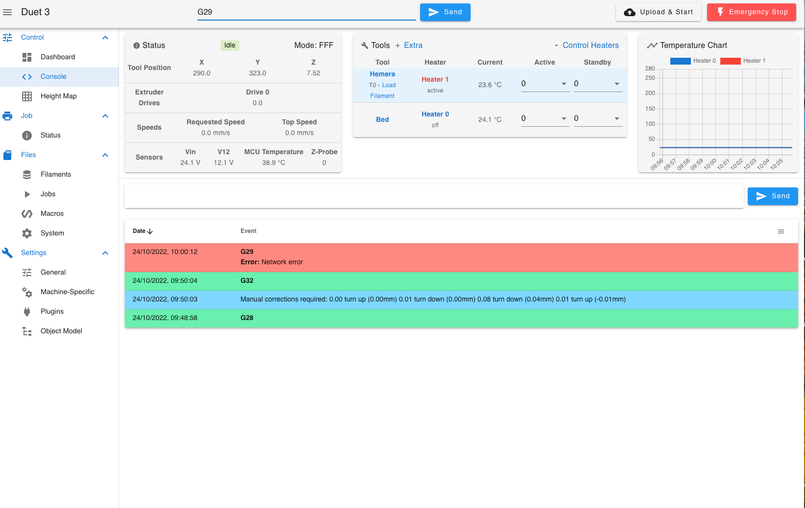
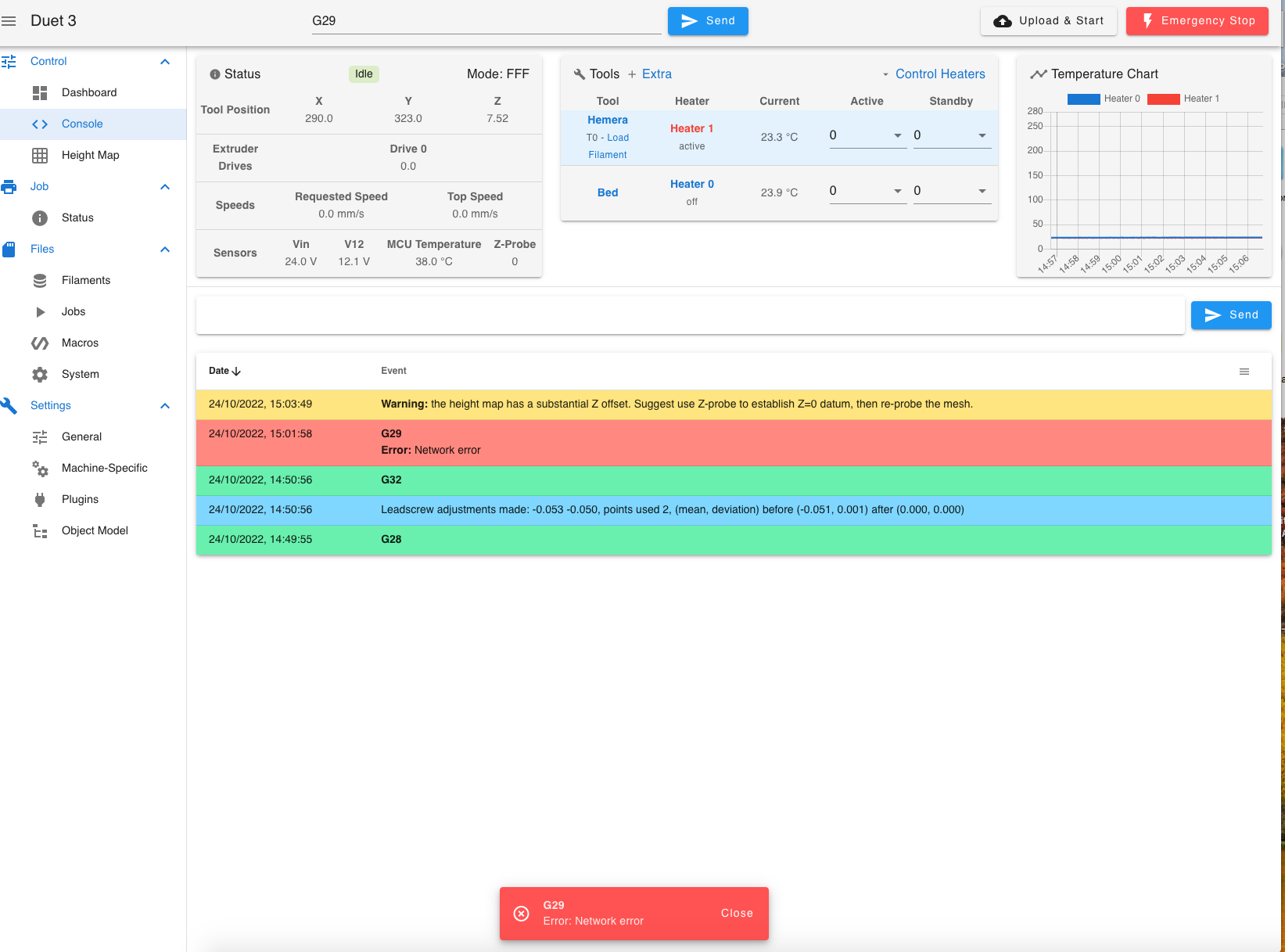
                It's generally doing 2 runs of the bed compensation, and half way through the 2nd DWC throws up a network error.

                So I've now disabled wifi on my Raspberry pi (running the Duet in SBC mode on a RPI 4B), and connected it to my networtk.

                I send;
                G28
                G32
                G29
                It runs the bed compensation twice. Half way through the 2nd bed compensation it still throws up a network error, while connected to ethernet.

                So the problem still persists on both wifi and ethernet.

                Screen shot from my computer of DWC console;
                Screen Shot 2022-10-24 at 10.05.41.png

                2 Photos of monitor connected to my RPi;
                IMG_1411.jpg IMG_1410.jpg

                I'm now going to try it again solely connected with a ethernet cable directly from my Pi to my computer.

                jay_s_ukundefined 1 Reply Last reply Reply Quote 0
                • jay_s_ukundefined
                  jay_s_uk @Dizzwold
                  last edited by

                  @Dizzwold have you modified the bed file in any way or is the one you posted higher up still valid?

                  Owns various duet boards and is the main wiki maintainer for the Teamgloomy LPC/STM32 port of RRF. Assume I'm running whatever the latest beta/stable build is

                  Dizzwoldundefined 1 Reply Last reply Reply Quote 0
                  • Dizzwoldundefined
                    Dizzwold @jay_s_uk
                    last edited by

                    @jay_s_uk

                    Still valid;

                    ; bed.g
                    ; called to perform automatic bed compensation via G32
                    ;
                    ; generated by RepRapFirmware Configuration Tool v3.3.13 on Mon Sep 19 2022 16:04:20 GMT+0100 (British Summer Time)
                    ;M561 ; clear any bed transform
                    ;G29  ; probe the bed and enable compensation
                    
                    G28			; home
                    G30 P0 X5 Y5 Z-9999				; probe front left
                    G30 P1 X278 Y5 Z-9999			; probe front right
                    G30 P2 X278 Y302 Z-9999			; probe rear right
                    G30 P3 X5 Y302 Z-9999 S4  		 ;probe rear left
                    G1 X0 Y0
                    
                    ; Configuration file for Duet 3 MB 6HC (firmware version 3.3)
                    ; executed by the firmware on start-up
                    ;
                    ; generated by RepRapFirmware Configuration Tool v3.3.13 on Mon Sep 19 2022 16:04:20 GMT+0100 (British Summer Time)
                    
                    ; General preferences
                    M575 P1 S1 B57600                                  ; enable support for PanelDue
                    G90                                                ; send absolute coordinates...
                    M83                                                ; ...but relative extruder moves
                    M550 P"Duet 3"                                     ; set printer name
                    M669 K1                                            ; select CoreXY mode
                    
                    ; Bed Adjustment Screw Positions
                    M671 X5:278:278:5 Y5:5:302:302 P0.5					; front left, front right, back right, back left
                    
                    G4 S1												;wait for expansion boards to start
                    
                    ; Drives
                    M569 P0.0 S0                                       ; physical drive 0.0 goes backwards
                    M569 P0.1 S0                                       ; physical drive 0.1 goes backwards
                    M569 P0.2 S1                                       ; physical drive 0.2 goes forwards
                    M569 P0.3 S1
                    M569 P121.0 S0                                       ; physical drive 0.3 goes forwards
                    M584 X0.0 Y0.1 Z0.2:0.3 E121.0                           ; set drive mapping
                    M350 X16 Y16 Z16 E16 I1                            ; configure microstepping with interpolation
                    M92 X80.00 Y80.00 Z400.00 E333.40                  ; set steps per mm
                    M566 X900.00 Y900.00 Z60.00 E120.00                ; set maximum instantaneous speed changes (mm/min)
                    M203 X6000.00 Y6000.00 Z180.00 E1200.00            ; set maximum speeds (mm/min)
                    M201 X500.00 Y500.00 Z20.00 E250.00                ; set accelerations (mm/s^2)
                    M906 X900 Y900 Z900 E800 I30                       ; set motor currents (mA) and motor idle factor in per cent
                    M84 S30                                            ; Set idle timeout
                    
                    ; Axis Limits
                    M208 X-2 Y-8 Z0 S1                                 ; set axis minima
                    M208 X330 Y330 Z400 S0                             ; set axis maxima
                    
                    ; Endstops
                    M574 X1 S1 P"!121.io1.in"                              ; configure switch-type (e.g. microswitch) endstop for low end on X via pin !io1.in
                    M574 Y1 S1 P"!io2.in"                              ; configure switch-type (e.g. microswitch) endstop for low end on Y via pin !io2.in
                    
                    
                    ; Z-Probe
                    M574 Z1 Z1 S2									   ; set endstops controlled be probe
                    M558 P8 C"^!121.io0.in" H5 F120 T6000                 ; set Z probe type to switch and the dive height + speeds
                    G31 P500 X-46 Y-19 Z2.52                            ; set Z probe trigger value, offset and trigger height
                    M557 X19:244 Y-2:304 P9                           ; define mesh grid
                    
                    ; Heaters
                    M308 S0 P"temp0" Y"thermistor" T100000 B4138       ; configure sensor 0 as thermistor on pin temp0
                    M950 H0 C"out0" T0                                 ; create bed heater output on out0 and map it to sensor 0
                    M307 H0 R0.187 K0.192:0.000 D1.89 E1.35 S1.00 B0   ; disable bang-bang mode for the bed heater and set PWM limit
                    M140 H0                                            ; map heated bed to heater 0
                    M143 H0 S120                                       ; set temperature limit for heater 0 to 120C
                    M308 S1 P"121.temp0" Y"thermistor" T100000 B4138       ; configure sensor 1 as thermistor on pin temp1
                    M950 H1 C"121.out0" T1                                 ; create nozzle heater output on out1 and map it to sensor 1
                    M307 H1 R2.498 K0.275:0.349 D6.79 E1.35 S1.00 B0 V24.0  ; disable bang-bang mode for heater  and set PWM limit
                    M143 H1 S280                                       ; set temperature limit for heater 1 to 280C
                    
                    ; Fans
                    M950 F0 C"121.out1" Q500                               ; create fan 0 on pin out4 and set its frequency
                    M106 P0 C"Print Cooler" S0 H-1                     ; set fan 0 name and value. Thermostatic control is turned off
                    M950 F1 C"121.out2" Q500                               ; create fan 1 on pin out5 and set its frequency
                    M106 P1 C"Extruder Cooling" S1 H1 T45              ; set fan 1 name and value. Thermostatic control is turned on
                    
                    ; Tools
                    M563 P0 S"Hemera" D0 H1 F0                         ; define tool 0
                    G10 P0 X0 Y0 Z0                                    ; set tool 0 axis offsets
                    G10 P0 R0 S0                                       ; set initial tool 0 active and standby temperatures to 0C
                    
                    ; Custom settings are not defined
                    ; Emergency Stop
                    M950 J1 C"io4.in"
                    M851 P1 T0 S0 R0
                    
                    
                    ; Miscellaneous
                    M911 S10 R11 P"M913 X0 Y0 G91 M83 G1 Z3 E-5 F1000" ; set voltage thresholds and actions to run on power loss
                    
                    T0
                    
                    M501
                    
                    jay_s_ukundefined 1 Reply Last reply Reply Quote 0
                    • jay_s_ukundefined
                      jay_s_uk @Dizzwold
                      last edited by

                      @Dizzwold the only thing that jumps out at me as being strange is you tell the firmware you have 4 screws, and probe 4 points but only have 2 motors. I would suggest that this may be causing you issues.
                      you should only set the 2 positions where the bed pivots on the z motor mounts

                      Owns various duet boards and is the main wiki maintainer for the Teamgloomy LPC/STM32 port of RRF. Assume I'm running whatever the latest beta/stable build is

                      Dizzwoldundefined 1 Reply Last reply Reply Quote 0
                      • Dizzwoldundefined
                        Dizzwold @jay_s_uk
                        last edited by

                        @jay_s_uk

                        Okay, I'll change that.

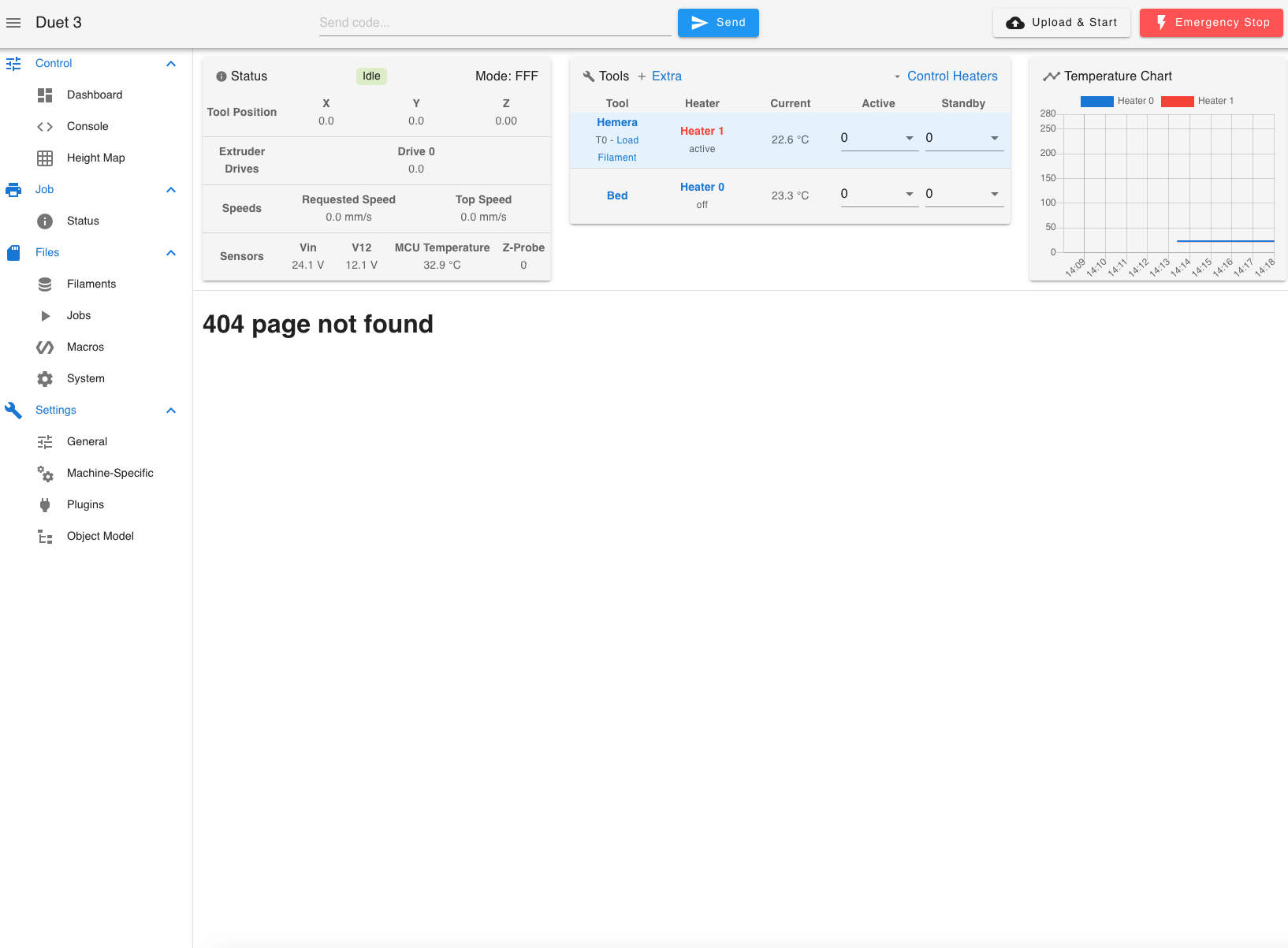
                        I had problems connecting directly. I couldn't connect, so I've been a purchase one of these RJ45 testers and everything was fine. Checked the address again in the monitor connected to the RPi and the address completely changed, xxx.xxx.xxx.xxx/16, butwith a 404 page not found?
                        Screen Shot 2022-10-24 at 14.17.55.png

                        I'll change the bed.g now and run another test.

                        Dizzwoldundefined 1 Reply Last reply Reply Quote 0
                        • Dizzwoldundefined
                          Dizzwold @Dizzwold
                          last edited by

                          @jay_s_uk

                          Thank you for pointing this out and correcting me on the correct path.

                          I remember reading about the leadscrew positions when I purchased the Duet over a year ago, and I think it was in the old guide (was it the RRF2 configure?), but when I used the configurer, when I finally got around to installing the Duet, things had changed and I didn't see anything regarding the leadscrew positions.
                          After I'd configured the duet I thought about this, so had a little search around. As I didn't find much to date on this, I just presumed things had moved on and this was no longer needed.
                          The guide does also state that for a bed like mine, to use the bed.g and give the positions of the screws to level it (using the manual bed levelling process, not the leadscrews).

                          Maybe I got confused?

                          Anyhow, I've changed the bed.g and config.g to suit the positions of my 2 leadscrews.

                          I'm now on ethernet, on my network, wifi disabled on the RPi and all my cables checkout okay.

                          Guess what. Only 1 scan with the bed compensation now and not 2 or 3, but still throwing up a network error?
                          Screen Shot 2022-10-24 at 15.06.36.png

                          I didn't have either the bed or nozzle heaters on for this, so going to d another PID for the nozzle before I try the bed compensation again.

                          At-least some progress. Thank you.

                          jay_s_ukundefined 1 Reply Last reply Reply Quote 0
                          • jay_s_ukundefined
                            jay_s_uk @Dizzwold
                            last edited by

                            @Dizzwold do you have any more information on the probe you are using?

                            Owns various duet boards and is the main wiki maintainer for the Teamgloomy LPC/STM32 port of RRF. Assume I'm running whatever the latest beta/stable build is

                            Dizzwoldundefined 1 Reply Last reply Reply Quote 0
                            • Dizzwoldundefined
                              Dizzwold @jay_s_uk
                              last edited by Dizzwold

                              @jay_s_uk

                              Not a great deal. I asked Tronxy and they either don't want to give much detail of they don't know. Here's there reply when I asked for details;
                              The TR leveler has no parameters.
                              All I know is it's 6-32v (won't work on 5v), NPN inductive glass sensor. I've connect it to the 24v power in on the Fysetc toolboard v1.0.
                              From my understanding it's similar to the PL-08N, except it will detect glass, and pretty good at doing so imo, although I've only used it with the ‘Lattice Glass’ that comes with it.
                              Blue cable = -v wired to toolboard io0 gnd
                              Black cable = signal wired to toolboard io0 in
                              Brown cable = +v wired to Vin power in on toolboard

                              jay_s_ukundefined 1 Reply Last reply Reply Quote 0
                              • jay_s_ukundefined
                                jay_s_uk @Dizzwold
                                last edited by

                                @Dizzwold no more thoughts on that then.
                                have you tried running the 6HC in standalone mode if you're using ethernet?
                                avoiding the SBC route is typically my advice anyway

                                Owns various duet boards and is the main wiki maintainer for the Teamgloomy LPC/STM32 port of RRF. Assume I'm running whatever the latest beta/stable build is

                                Dizzwoldundefined 1 Reply Last reply Reply Quote 0
                                • Dizzwoldundefined
                                  Dizzwold @jay_s_uk
                                  last edited by

                                  @jay_s_uk

                                  Hmm, no I've not tried it in stand alone.

                                  To do so will I have to restart again with the configuration tool?

                                  jay_s_ukundefined 1 Reply Last reply Reply Quote 0
                                  • jay_s_ukundefined
                                    jay_s_uk @Dizzwold
                                    last edited by

                                    @Dizzwold you can download all your config files from the printer before you switch over, so download everything from the sys folder.
                                    You'll need to add M552 S1 P0.0.0.0 somewhere in your config.g to turn on the ethernet interface.
                                    https://docs.duet3d.com/en/User_manual/Overview/Getting_started_Duet_3_MB6HC#getting-started
                                    Then use another SD card and put the downloaded files in a folder called sys in the root of the SD card
                                    Also download DWC for the version you're running from here https://github.com/Duet3D/RepRapFirmware/releases and extract it to a folder called www in the root of the sd card.
                                    Pop that in your machine and you should be good to go.

                                    Owns various duet boards and is the main wiki maintainer for the Teamgloomy LPC/STM32 port of RRF. Assume I'm running whatever the latest beta/stable build is

                                    Dizzwoldundefined 1 Reply Last reply Reply Quote 0
                                    • Dizzwoldundefined
                                      Dizzwold @jay_s_uk
                                      last edited by

                                      @jay_s_uk

                                      Lol, I've only got 64gb sd cards spare, not 32gb, what a dilemma to have.

                                      I was just looking at the page you've linked to (getting started), I was also looking at setting up a fixed ip on the next page (getting connected).

                                      Looks like I'll have to wait for nozama to deliver some 32gb cards tomorrow (i read somewhere you shouldn't go above that). Thinking about it I still have the original sd card that came with the unit.

                                      jay_s_ukundefined 1 Reply Last reply Reply Quote 0
                                      • jay_s_ukundefined
                                        jay_s_uk @Dizzwold
                                        last edited by

                                        @Dizzwold yes, fat32 only originally supported up to 32gb. you can force a 64gb to partition etc but its too much effort

                                        Owns various duet boards and is the main wiki maintainer for the Teamgloomy LPC/STM32 port of RRF. Assume I'm running whatever the latest beta/stable build is

                                        Dizzwoldundefined 1 Reply Last reply Reply Quote 0
                                        • Dizzwoldundefined
                                          Dizzwold @jay_s_uk
                                          last edited by

                                          @jay_s_uk

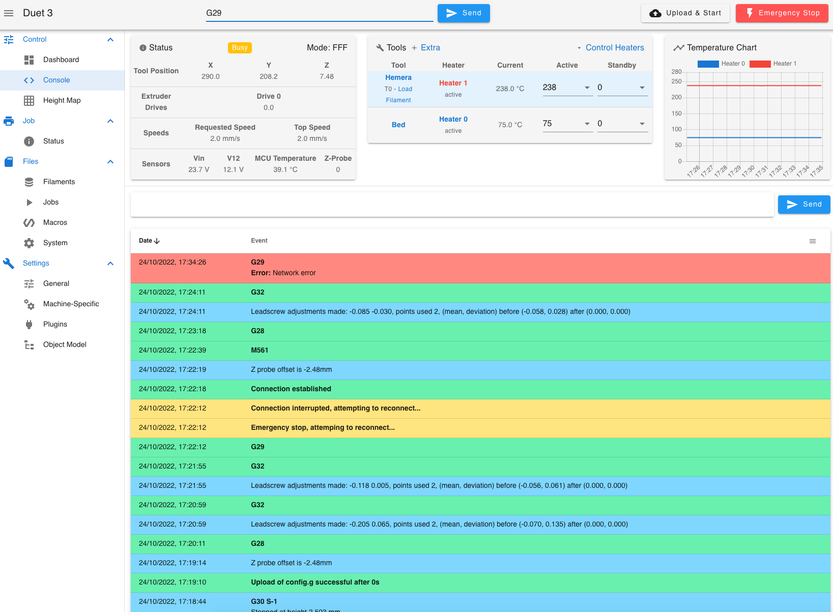
                                          Just tried it again after nozzle pid, heaters on G28, G32, G29;
                                          Screen Shot 2022-10-24 at 17.25.34.png
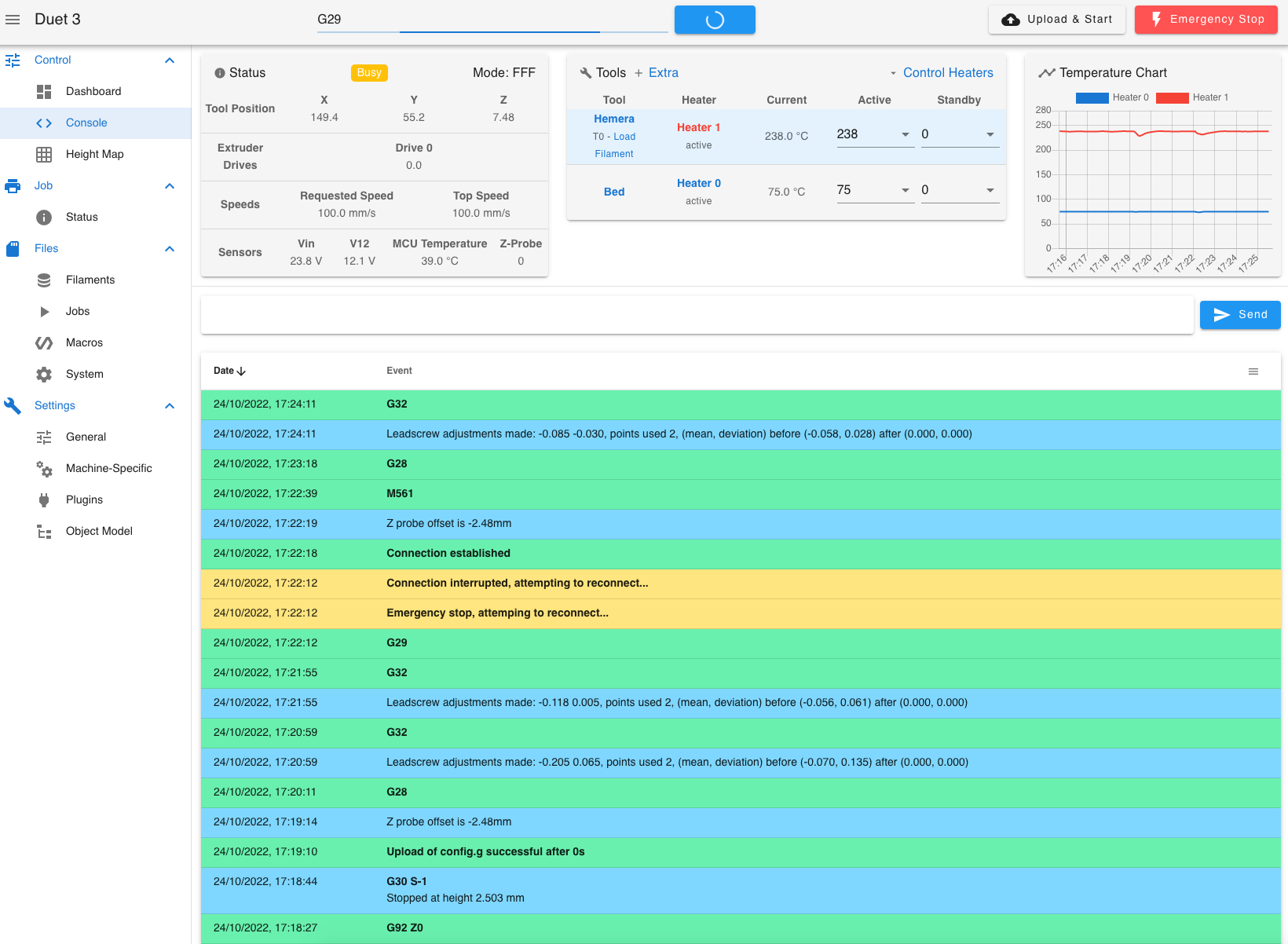
                                          It scanned twice again and through up the network error on the 5th row (9 across x 9 front to back), on the second scan.
                                          Screen Shot 2022-10-24 at 17.35.00.png

                                          jay_s_ukundefined 1 Reply Last reply Reply Quote 0
                                          • jay_s_ukundefined
                                            jay_s_uk @Dizzwold
                                            last edited by

                                            @Dizzwold you must have a G29 somewhere in your files as that's what will do the 9x9

                                            Owns various duet boards and is the main wiki maintainer for the Teamgloomy LPC/STM32 port of RRF. Assume I'm running whatever the latest beta/stable build is

                                            Dizzwoldundefined 1 Reply Last reply Reply Quote 0
                                            • First post
                                              Last post
                                            Unless otherwise noted, all forum content is licensed under CC-BY-SA