Duet 3 mini 5+/FYSETC Big Dipper on FFCP/Flashforge Creator Pro
-
@Inlinebrother Oozing is specific to that kind of dual hotend setup, nothing to do with the big dipper.
The Z offset I am referring to is the actual height of the nozzles -- they will be somewhat disparate due to differences when screwing them into the hotend and manufacturing tolerances.
-
 undefined T3P3Tony moved this topic from Duet Hardware and wiring
-
Ok, I want to share one of the first steps that I went through yesterday.
I received different kinds of connectors that are listed in specs and continued with the project to prepare and install Fysetc Big Dipper.
The first thing you have to do while you have easy access to type c port is to install firmware and setup wifi.
But before that you have to connect to PC or Mac. I used mac to setup everything. The Duet 3 mini5+ docs are actually very helpful, and for now I haven't found any big differences besides the 5v select that I mention below.
First thing you might encounter is that there is no power via type c. You have to move a 5v select switch to another corner. Also attach the antenna for better signal.
I used this doc to connect https://docs.duet3d.com/en/How_to_guides/Getting_connected/Getting_connected_to_your_Duet
At first I used screen tool in terminal to connect, but if you have simplify3d you can do that from there, it is much more convenient.
To control your board you will need to use Gcodes from here https://docs.duet3d.com/User_manual/Reference/GcodesThe firmware that was installed on Fysetc Big Dipper was 3.5.0 rc3 for Duet 3 mini5+ (M115). For some reason the guys from FYSETC installed the rc version. And also something was missing. I guess wifi server needed to be installed. Also there was no SD card. So I had to prepare one myself.
To prepare an SD card on macOS I had to use the official SD card formatter from SD card association. The macos disk utility for some reason left traces of exFAT on the sd card (this SD card was previously used in a phone with some custom formatting)
Also for Duet Web Control to run I had to use a firmware configurator and try to create the config for printer, though for now I don't know some specifics about the wiring, for example I don't know how to setup the led strip that comes with the printer. Also the direction of the drives is not obvious for me.After the config was ready I put these three directories that were generated on the SD card.
First time the SD card didn't mount because of the exFAT file system. After formatting that thing was fixed.But then I had issues with reconnecting to wifi. I have several guesses.
First I updated all the firmware to the latest stable version. For that you have to first download files from the Github and place
Duet3Firmware_Mini5plus.uf2
Duet3_SDiap32_Mini5plus.bin
DuetWiFiServer.bin
to a firmware folder
You might also see the first two files generated by the configurator but I don't trust them and I think the best way is to use the files from the github release zip archive. Besides the configurator for some reason is missing the wifi server file.
At first i tried the M997 S0:1 command, but then I repeated this command for wifi server only M997 S1
Then I also tried not to connect to the board via SImplify3d, after I did all the setup.
And these two steps helped the board not to loose connection to a Wifi network for 10 minutes that I tested that. I will have to make a longer test, but I think it will happen when I will start printing.Ok so after that I had the board connected to my wifi and it is now prepared for the next step. Next I will have to wire everything, put labels on cables and revisit the config files and update according to new info.
-
Hi, again, today I overcame my fear and started to crimp.
All in all for FFCP you need to crimp
- all four fans 1.board fan 2. cooler fan 3.extruder 1 fan 4. extruder 2 fan
- five stepper motors
- 3 end stop switches (x/y/z)
- hotbed thermistor 4 pin to 2
- LED strip because the board uses 3pin connector for that instead of 4 pin, but I am not yet sure that the original LED strip is supported
Today I crimped stepper motors and 2 endstops
Stepper motors are easy to crimp, because you only have to check the right order of the cables.
Endstops have 4 pins, but you have to use a 5 pin connector and use only three pins out of them, because Big Dipper/Duet has only one ground. I crimped both grounds together, but if that's wrong please point it out before I plug it in)I used these two schemes for that
https://www.geeetech.com/wiki/index.php/Mighty_Board#Interface_Layout
https://wiki.fysetc.com/BIG-DIPPER/#3d-modeland I only needed xh2.54 connectors, thanks for the advice @Exerqtor
Crimping process is a new thing for me, so I had to watch some videos to undestand the idea)
For those like me, in a few words, you have to use a crimper tool like SN-2549 and squeeze the tail leaving the front part with a locklng tab intact. Also the idea is to squeeze the tail to fix the cable insulation, so the exposed part of the conductor shouldn't be too long. But I have yet to check my crimping skills, after I finish that process.
Also I accidentaly damaged end stop cable, because I thought it was a bad cable, but it turned out I am the one who is bad at electronics) I guess they make a special GND cable without insulation to take off interference from y and z axis of endstops. For some reason x endstop cable uses another shielding and there is no exposed wires there. So i ripped z axis cable apart and now I am waiting for a new one from ali.
In the meantime I'll finish with other components.
I also checked my adapter design for the Big Dipper
It is ok, but I will have to use only 3 out of 5 screws, because some holes are below the board and the board might touch the screws.
Also I guess I'll have to turn the board in such a way that stepper driver chips are not directly in the line of sight of the board fan. But I think the space between the board and the case would be enough to ensure some airflow. Also I think to add heat sinks, although FYSETC says that they are not necessary.I also ordered an extender for type-c, to make access to the board easier.
As far as WiFi is concerned, I don't want to make holes, so I'll try to design a holder that will be placed on top of the holes for old reset button and mightyboard data port. But for that i will need to start printing, so it'll have to wait) -
the endstops need to be wired individually. See the diagram
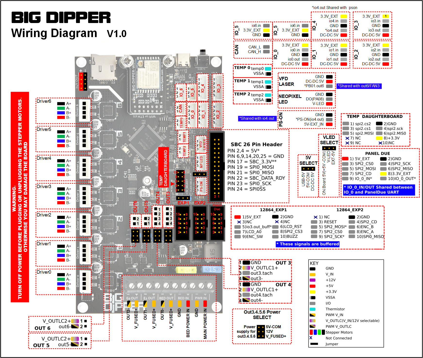 .
. -
@oliof Hi, thanks, I don't understand what you mean though.
Actually forgot to mention where I plan to put which cabel. Maybe that will clear things out
- So with drivers everything is obvious
- Endstops according to docs under the scheme are going into io_0-io-6 ports.
MightyBoard endstops Mech 1.3v have 4 pins (signal, GND,GND, 5v)
So I decided to use three out of five pins for each endstop based on this doc https://docs.duet3d.com/User_manual/Connecting_hardware/Sensors_endstops
signal == io_in
gnd1 + gnd2 == gnd
vcc/5v == DC-DC 5V - Fans will go into out_3-out_6 ports
+positive cable will go into - V_OUTLC1+
-negative cable will go into - out- - Board thermistor will maybe go into temp0-temp2 and again 4 pins should become 2 pins. But according to mightyBoard pinout it has
HB_T
GND
GND
5v
And what is bothering me is that it needs some power and maybe should go into one of the io ports and not temp - I have a daugherboard for extruder thermocouples
- Power cables go where they should.
But I have only two cables for the bed,
so I guess
+positive will go into - BED POWER IN
-negative will go into - OUT0- - And LED should go into NP_LED I suppose, but it is hard for me to understand what pins should go where.
According to mightyboard doc the LED has 4 pins
24v
LED0
LED1
LED2
And Big Dipper has 3
GND
DO(PA8)
V-LED
I guess V-LED might be the power pin. But other pins seem incompatible
-
looks like the mechanical endstops have gnd and signal for the end stop, and gnd and vin for the activity LED. I don't know if its advisable to tie gnd together in this case as vin for the led may interfere with signal. I'd personally forego attaching the LED.
<>RatRig V-Minion Fly Super5Pro RRF<> V-Core 3.1 IDEX k*****r <> RatRig V-Minion SKR 2 Marlin<>
-
@Inlinebrother NP Led is for Neo pixel LEDs and not related to individual dumb LEDs.
-
Hi, some updates
I received an endstop cable
And yesterday, after a month or two found some motivation to start checking how it works
So here is the list of what is checked right now
Power applied via standard for FFCP cables is working OK
I can connect to WiFi via Big Dipper when 24v is applied OK
(though you can't use USB 5v and 24v interchangeably to configure WiFi, because you have to move the selector physically. So if you want only to connect to USB and configure WiFi you have to move selector. If you want to use 24v and have a working WiFI you have to return the selector to the default state)
XYZ motors are moving when command is sent via WiFi OK
XYZ endstops are flashing when triggered OK
(though I don't know how to check whether endstops are working as expected before I try to home axis)Next steps
check fans
check thermistors
check heaters
Then close the case and try to configure the print -
Next update:
Extruder Fans OK
Cooling Fan (with ability to control air flow from 0 to 100) OKNext steps:
Forgot to crimp board fan cable TODO
Fix wrong wiring of the Bed thermistor TODO
Have to recrimp x axis motor cable TODO
check thermocouples are working when there are no config errors TODO
and heaters
(found a thread about bed thermistor here - https://forum.duet3d.com/topic/7285/flashforge-creator-pro-heat-bed-wiring/2) -
Next update:
-
By using the thread above now I see the bed temperature via a thermistor OK
used first two cables out of 4 (white and green in my case) -
Config from this thread helped me to turn on thermocouples (though i had to downgrade them to thermocouple-max31855 from thermocouple-max31856) OK
-
board fan working OK
-
extruder heaters are working OK
-
bed heater is not working, I'll check what's wrong next time TODO
-
Also I need to close the printer TODO
-
LEDs are not working and I don't think I am going to fix that in the nearest future NOT_HAPPENING
I might replace the screen with the one from FYSETC TODO -
Fix config issues that i can come across TODO
-
And finally print something TODO
-
-
Hi, everyone, if you are reading this, then I....
Finally finished assembling the printer after the upgrade)
-
I managed to home all axes OK
-
Added a fysetc 12864 screen, though it needs an adapter OK
I used the menu made by jadonmmiller
But I'll have to update the UI because this one is only for 1 extruder setup -
Drivers are doing their job, I hear almost only fans) OK
-
Figured out why the bed was not heating, it has a separate power input, and I had to buy another cable and crimp it OK
-
For now I skipped BLTouch sensor installation, because I don't want to make it even harder.
-
I started to configure the printer
And it seems that I'll have to read Gcode docs and learn Gcode, because it is everywhere
From screen menu and configs to printing instructions -
At the moment I have to find Gcodes to load/unload filaments and check that extruders directions are correct TODO
-
Then I'll have to configure Cura TODO
Somehow I used the printer without Gcode knowledge before that)
-
-
So I found gcodes in docs to load/unload filament
Then I had to change some configs for extruder drives
And now I got a problem with thermocouple board because there is interference from stepper motor cabelsIt seems that Flashforge fixed that issue in their version of mighty board, because i did nothing to the cables other than changing connectors
I have a 0.2v daughterboard and I think in 0.2v there was no capacitor
according to this thread adding a capacitor helps https://forum.duet3d.com/topic/1270/thermocouple-issues/10@dc42 Hi, sorry to tag you, but can you please confirm that in the daughterboard 0.2v there was no capacitor?
As far as I see from the picture of the daughterboard on the official site, the new version has some extra components on top of it
mine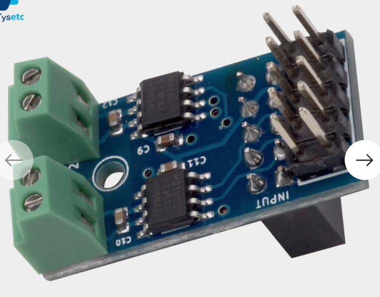
from the site
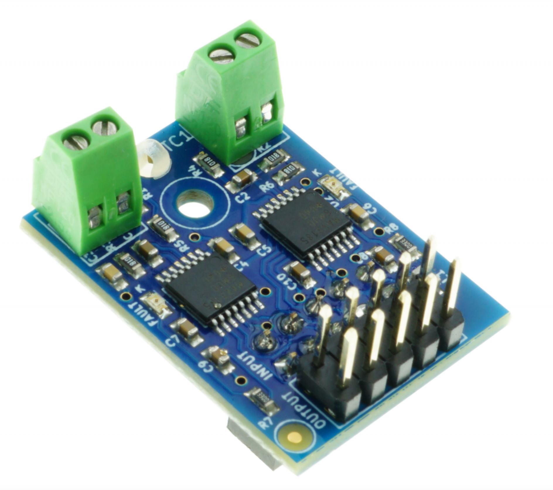
And is the process the same for the 0.2v board?
- Take 4 capacitors
- find a ground plate
- solder capacitors to each pin and to the ground
-
Ok, I found your answer for the same question here
So i think one of the ways to fix that is to get the wire out of the casing -
But moving the thermocouple wires away from the other wires didn't help
Only one of the thermocouples for the right extruder now is working correctly, but i can't say exactly what helped, maybe i crimped it better. Although it still can catch the interference from the other thermocouple, even if using it alone does not provoke interference
They are still near the drives on the head, and i think that is where they pick this interferenceI wonder if using a thermistor will help
Flexion extruder allows to install it, and the board has ports for temp sensors -
recrimping didn't help, i think I'll have to go with the thermistor
that way i will not need a daughterboard and i guess that might help -
Captain's log
Installed and configured thermistor NTC 3950
Now I don't see 2000 degrees when extruding or retracting filamentBut my printer shuts down in a minute after that and then it is trying to restart over and over again, until I turn it off and turn on again
-
It seems that @dc42 helped me again, even without saying a thing)
I found my answer here https://forum.duet3d.com/topic/15897/duet-wifi-resetting-part-way-through-prints/30
I disabled endstops, and it seems that the problem is solved
Though I need to wire the endstops properly -
@oliof I think you are right, I didn't understand you at first) thank you)
-
Sooo, I did recrimp endstops
Thought now it is ready to go,
connected Cura via plugin OK
Started to heat the bed
After the extruder fan started to work the printer started to restart again
Then in a few minutes, after the printer cooled down, I thought I'll try to change some settings for fans
But the printer began to restart in an idle mode. I did nothing, and it started its disco.Now I don't know what can be the problem
Maybe something should be done to a board fan frequency, that is the only thing working when the printer is idle -
Ok I started from scratch
I think the problem was with the board loosely fixed, it might have touched some parts of the case
I also checked all the wires and reinserted them, trying to fix them as tight as possible
Now it seem to workStarted the test print, I'll write an update after that
For now I hear the sound of silence and it is great
I'll have to change the coordinates though, the print started on the corner of the build plate