Duet3D Logo Duet3D
    • Tags
    • Documentation
    • Order
    • Register
    • Login

    Yet another cast aluminum plate topic...

    Scheduled Pinned Locked Moved
    General Discussion
    17
    106
    12.1k
    Loading More Posts
    • Oldest to Newest
    • Newest to Oldest
    • Most Votes
    Reply
    • Reply as topic
    Log in to reply
    This topic has been deleted. Only users with topic management privileges can see it.
    • dc42undefined
      dc42 administrators
      last edited by dc42

      @TLeTourneau, you will find different opinions on that. I prefer to use a removable glass plate so that I can swap print beds easily. The main benefit is that if a print sticks too well to the bed, I can put the bed+print in the fridge or freezer to help it to come free. Also I can swap plates and start a new print after one has finished, without waiting for the bed to cool down (which can take a while if you are using a thick aluminium plate). Finally, I can experiment with different print surfaces (plain glass, PEI, PrintBite etc.) on top of the glass plates.

      The disadvantages of using glass on top is that you need to have space at these margin for bed clips (which loses a little print area unless you included a margin in your bed design), and the temperature on top of the glass will be lower than on the aluminium by 5 to 10C.

      If you do use glass then I suggest 4mm thick not quarter inch. Ordinary float glass is usually flatter than toughened glass.

      Duet WiFi hardware designer and firmware engineer
      Please do not ask me for Duet support via PM or email, use the forum
      http://www.escher3d.com, https://miscsolutions.wordpress.com

      1 Reply Last reply Reply Quote 1
      • taconiteundefined
        taconite
        last edited by

        Because you use cast aluminium there is no need for a glass on top in my opinion (that just increases the heat up time and weight)

        Custom ANET A8
        Custom Delta: D-PATCH (Delta Printer with Automatic Tool CHanging) https://forum.duet3d.com/topic/16082/d-patch?_=1596131234754

        All I do here is under this license: CC BY-NC-SA

        1 Reply Last reply Reply Quote 1
        • deckingmanundefined
          deckingman @TLeTourneau
          last edited by deckingman

          @tletourneau You'll get dozens of different opinions on this. IMO, there is no right or wrong - it's just personal preference. Like DC42, I prefer the removable glass option and for the same reasons. I use 6mm thick float glass (1/4 inch) because my bed is on the large side, and it's fine. Just allow for the top surface of the glass to be about 2 deg C less than the aluminium under it.

          Edit. Because aluminium is a soft metal, it's not too difficult to scratch or dent it. Especially if you print directly on to it and resort to using a scraper or some such to remove a part. So I'd highly recommend that you put something on top of it, whether that be semi-permanent of easily removable.

          Ian
          https://somei3deas.wordpress.com/
          https://www.youtube.com/@deckingman

          1 Reply Last reply Reply Quote 1
          • taconiteundefined
            taconite
            last edited by taconite

            @deckingman
            I will use a magnetic printbed like Ziflex or easy-peelzy (but they are not that good for ABS because of temperature resistance of the magnets)
            I backed them back on kickstarter but didn't receive my item yet
            EDIT: Ziflex can be heated up to 100°C before loosing its power.

            Custom ANET A8
            Custom Delta: D-PATCH (Delta Printer with Automatic Tool CHanging) https://forum.duet3d.com/topic/16082/d-patch?_=1596131234754

            All I do here is under this license: CC BY-NC-SA

            1 Reply Last reply Reply Quote 0
            • TLeTourneauundefined
              TLeTourneau
              last edited by

              Well the plate and heater are installed, now to run a mesh and see what it looks like. Here are some pictures.

              Here's the cast aluminum plate:
              0_1549337094414_ATP5.jpg

              Here is a view of the frame I made to mount the plate:
              0_1549337100859_Bottom.jpg

              Here is the front with the plate on the mount:
              0_1549337144603_Front.jpg

              Here is a closer look at the front mount:
              0_1549337181624_FrontMount.jpg

              Here is the rear left mount:
              0_1549337213082_RearLeft.jpg

              And the rear right mount:
              0_1549337254796_RearRight.jpg

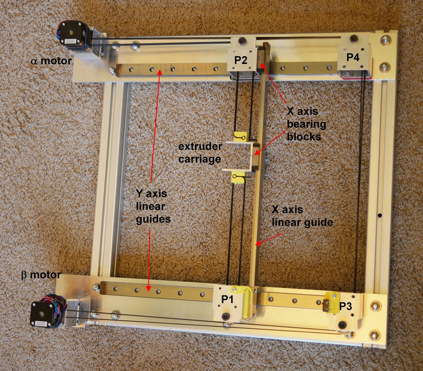
              I also installed linear rails on the X and Y axis's:
              0_1549337285705_LinearRails.jpg

              I just thought I'd share. 🙂

              Thanks,
              Tom

              TronXY X5S-500 (CoerXY)
              Duet 2 Ethernet v1.04
              Firmware Version: 2.02(RTOS) (2018-12-24b1)
              Web Interface Version: 1.22.6
              7" PanelDue
              E3D V6 Clone
              MOSFET's for hot end
              1000w Keenovo with SSR for heat bed
              dc42 Mini IR Sensor or BLTouch

              Phaedruxundefined Wyvernundefined 2 Replies Last reply Reply Quote 1
              • Phaedruxundefined
                Phaedrux Moderator @TLeTourneau
                last edited by

                @tletourneau run a detailed G29, let's see how flat that sucker is.

                Z-Bot CoreXY Build | Thingiverse Profile

                1 Reply Last reply Reply Quote 0
                • TLeTourneauundefined
                  TLeTourneau
                  last edited by

                  Well this is strange to me, any thoughts on how to adjust this?

                  0_1549337772518_Bed_Level_001_25point_02042019.PNG

                  Here is the CSV data:

                  ![0_1549337859931_e881a336-6481-45cb-b379-0bad0597e5da-image.png](/assets/uploads/files/1549337860273-e881a336-6481-45cb-b379-0bad0597e5da-image.png) 
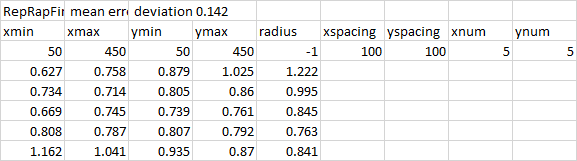
                  RepRapFirmware height map file v2	 mean error 0.847	 deviation 0.142						
                  xmin	xmax	ymin	ymax	radius	xspacing	yspacing	xnum	ynum
                  50	450	50	450	-1	100	100	5	5
                  0.627	0.758	0.879	1.025	1.222				
                  0.734	0.714	0.805	0.86	0.995				
                  0.669	0.745	0.739	0.761	0.845				
                  0.808	0.787	0.807	0.792	0.763				
                  1.162	1.041	0.935	0.87	0.841				
                  

                  This is using a BLTouch, the Z-probe settings are:

                  ; Z-Probe
                  ; BLTouch
                  M574 Z1 S2                                         ; Set endstops controlled by probe
                  M307 H7 A-1 C-1 D-1                                ; Disable heater on PWM channel for BLTouch
                  M558 P9 H5 F100 T6000 A10 R0.3 S0.01 B1            ; Set Z probe type to bltouch and the dive height + speeds
                  G31 P25 X59 Y-12 Z.92                              ; Set Z probe trigger value, offset and trigger height
                  M557 X50:450 Y50:450 S150                          ; Define mesh grid
                  

                  Thanks,
                  Tom

                  TronXY X5S-500 (CoerXY)
                  Duet 2 Ethernet v1.04
                  Firmware Version: 2.02(RTOS) (2018-12-24b1)
                  Web Interface Version: 1.22.6
                  7" PanelDue
                  E3D V6 Clone
                  MOSFET's for hot end
                  1000w Keenovo with SSR for heat bed
                  dc42 Mini IR Sensor or BLTouch

                  mrehorstdmdundefined 1 Reply Last reply Reply Quote 0
                  • Phaedruxundefined
                    Phaedrux Moderator
                    last edited by

                    Did you remeasure your z offset and manually level the bed first?

                    Z-Bot CoreXY Build | Thingiverse Profile

                    1 Reply Last reply Reply Quote 0
                    • TLeTourneauundefined
                      TLeTourneau
                      last edited by

                      Thanks for the reply! I did measure my Z offset using the method in the wiki. I thought I leveled my bed... I'll level it again to be sure and run it again.

                      Thanks,
                      Tom

                      TronXY X5S-500 (CoerXY)
                      Duet 2 Ethernet v1.04
                      Firmware Version: 2.02(RTOS) (2018-12-24b1)
                      Web Interface Version: 1.22.6
                      7" PanelDue
                      E3D V6 Clone
                      MOSFET's for hot end
                      1000w Keenovo with SSR for heat bed
                      dc42 Mini IR Sensor or BLTouch

                      1 Reply Last reply Reply Quote 0
                      • Wyvernundefined
                        Wyvern @TLeTourneau
                        last edited by

                        @tletourneau
                        Dat thicc boi

                        Is that 1/2 inch?

                        TLeTourneauundefined 1 Reply Last reply Reply Quote 0
                        • TLeTourneauundefined
                          TLeTourneau @Wyvern
                          last edited by

                          @wyvern said in Yet another cast aluminum plate topic...:

                          @tletourneau
                          Dat thicc boi

                          Is that 1/2 inch?

                          Naw, it's only 3/8". When I started to think about a 500x500mm piece I figured that about 9.5mm thick should be rigid enough for a 3 point mount. 🙂

                          Thanks,
                          Tom

                          TronXY X5S-500 (CoerXY)
                          Duet 2 Ethernet v1.04
                          Firmware Version: 2.02(RTOS) (2018-12-24b1)
                          Web Interface Version: 1.22.6
                          7" PanelDue
                          E3D V6 Clone
                          MOSFET's for hot end
                          1000w Keenovo with SSR for heat bed
                          dc42 Mini IR Sensor or BLTouch

                          Wyvernundefined 1 Reply Last reply Reply Quote 0
                          • Wyvernundefined
                            Wyvern @TLeTourneau
                            last edited by

                            @tletourneau
                            Crazy, my 1/4 300x300 should be here tomorrow, I just did 12mm Z rod/motor upgrade and .9 extruder upgrade, took the wimpy 8mm bars and reinforced some of the frame.

                            Been a busy last few days.

                            Since my platform is only ACM I need to go the 4 point route to prevent platform bow, but I can always add some 2020 on the underside if it clears the Z axis drive-train.

                            Putting PEI on top, never used it, but I finally am getting good results with glass, I found some magic hairspray!

                            TLeTourneauundefined 1 Reply Last reply Reply Quote 0
                            • TLeTourneauundefined
                              TLeTourneau @Wyvern
                              last edited by TLeTourneau

                              @wyvern I stuck with the 8mm lead screw but changed it to a single start 2mm lead from a four start 8mm lead which helped prevent bed drop, I am also using derlin anti-backlash nuts. I already had 12mm linear guide rods on the Z axis so I changed the bearings on them to a longer LMF12 to help control wobble which seemed to help. I figured that if I have issues I can always change the lead screws to 12mm/2mm but that would require me rebuilding the plate they, and the linear rods and bed, mount to so I thought I would try this first. If I have to change the mounting plates I'll likely add a Duex5 and go with three Z motors to enhance the auto bed leveling.

                              Thanks,
                              Tom

                              TronXY X5S-500 (CoerXY)
                              Duet 2 Ethernet v1.04
                              Firmware Version: 2.02(RTOS) (2018-12-24b1)
                              Web Interface Version: 1.22.6
                              7" PanelDue
                              E3D V6 Clone
                              MOSFET's for hot end
                              1000w Keenovo with SSR for heat bed
                              dc42 Mini IR Sensor or BLTouch

                              Wyvernundefined 1 Reply Last reply Reply Quote 0
                              • Wyvernundefined
                                Wyvern @TLeTourneau
                                last edited by

                                @tletourneau

                                I have 4 start leads but I also have 2:1 gearing, so I'm hoping the extra 3 pounds won't matter, I only have one larger .9 stepper

                                What has helped tremendously as far as bed drop is the use of anti-backlash nuts, they have a little pre-load and pushing down on the platform doesn't seem to make the axis go down.

                                I mostly am doing the bed upgrade so I do not have to rely on glass or auto-leveling, the less components and configuration I need, the better.

                                1 Reply Last reply Reply Quote 0
                                • SupraGuyundefined
                                  SupraGuy
                                  last edited by

                                  For your mesh grid, there's less than 0.5mm of warp measured, that is the difference in values from the high corners (1.222mm and 1.162mm and the centre at 0.739mm makes for a n average difference of 0.453mm.) This is really difficult to see with the naked eye, and the levelling report will exaggerate this.

                                  First things first, I'd check with a machinist straight edge that this warp actually exists. Measuring corner to corner, and assuming that this is accurate; you should see a very nearly straight measurement one way, and a slight gap in the center the other way.

                                  If indeed the plate is warped that way, you will want to see if this is from it being mounted down to the bed frame. It doesn't appear that it should be, but it's worth investigating. It may be that your machined flat plate has somehow become warped, perhaps in shipping, and maybe as an effect of the bed heater. 3/8" thick should be capable of maintaining flatness over that size, and your 3 point mount seems reasonable. Is it possible that this was machined to one side good, and you put the heater on the guaranteed flat side? It may be possible to have a local machine shop mill it flat, shouldn't be too unreasonably expensive, though it shouldn't need to be done for a piece that you bought specifically to be flat.

                                  Lead screw driven printer, powered by Duet 2 Wifi
                                  MPCNC powered by Duet 2 Wifi
                                  CoreXY printer driven by Duet 3 6HC
                                  LowRider CNC powered by Duet 2 Wifi

                                  1 Reply Last reply Reply Quote 0
                                  • mrehorstdmdundefined
                                    mrehorstdmd @TLeTourneau
                                    last edited by

                                    @tletourneau A 3/8" cast plate will not have warped in shipping or any other way short of driving a fork lift over it, and if that had happened, it would be obvious from damage to the plate.

                                    It looks to me like your Y axis guide rails are skewed in the YZ plane.

                                    https://drmrehorst.blogspot.com/

                                    SupraGuyundefined 1 Reply Last reply Reply Quote 0
                                    • UnderDoneSushiundefined
                                      UnderDoneSushi @gtj0
                                      last edited by

                                      @gtj0 Care to share what your mounting system looks like?

                                      1 Reply Last reply Reply Quote 0
                                      • SupraGuyundefined
                                        SupraGuy @mrehorstdmd
                                        last edited by

                                        @mrehorstdmd said in Yet another cast aluminum plate topic...:

                                        @tletourneau A 3/8" cast plate will not have warped in shipping or any other way short of driving a fork lift over it, and if that had happened, it would be obvious from damage to the plate.

                                        It looks to me like your Y axis guide rails are skewed in the YZ plane.

                                        LOL.

                                        Yeah, I had to step away from the keyboard for a bit before I could finish.

                                        If the plate is not warped, as verified by the machinist's straight edge, then what's warped is your print head movement, in which case you either want to fix that, or keep/use the mesh compensation to keep your prints flat relative to the bed. Usually if there is a sag in the rails, you'll see what looks like a hump in the center, instead of a dish like this. It doesn't appear to be in just the X or Y axis, but as a combination of both, almost exactly at 45 degrees.

                                        This could be a misalignment of the 2 Y linear rails, introducing a twist in the gantry movement. Like I said earlier, the amount is small, less than 0.5mm. (Well, maybe the misalignment is more like 0.6mm at the one end.)

                                        Lead screw driven printer, powered by Duet 2 Wifi
                                        MPCNC powered by Duet 2 Wifi
                                        CoreXY printer driven by Duet 3 6HC
                                        LowRider CNC powered by Duet 2 Wifi

                                        TLeTourneauundefined 1 Reply Last reply Reply Quote 0
                                        • Wyvernundefined
                                          Wyvern
                                          last edited by

                                          I use printed alignment tools for all linear rails just for this reason.

                                          1 Reply Last reply Reply Quote 0
                                          • mrehorstdmdundefined
                                            mrehorstdmd
                                            last edited by

                                            I mounted the Y axis rails on 1/4" MIC6 plates bolted to a 40mm square t-slot frame. That whole assembly then bolted into the printer's frame:

                                            alt text

                                            My original intention with this was to make a couple different height printer frames into which I could just drop this assembly. I didn't end up doing that, but it does seem to keep the rails parallel to each other.

                                            https://drmrehorst.blogspot.com/

                                            1 Reply Last reply Reply Quote 0
                                            • First post
                                              Last post
                                            Unless otherwise noted, all forum content is licensed under CC-BY-SA