Duet3D Logo Duet3D
    • Tags
    • Documentation
    • Order
    • Register
    • Login
    1. Home
    2. imadunatic
    • Profile
    • Following 0
    • Followers 0
    • Topics 3
    • Posts 7
    • Best 1
    • Controversial 0
    • Groups 0

    imadunatic

    @imadunatic

    1
    Reputation
    2
    Profile views
    7
    Posts
    0
    Followers
    0
    Following
    Joined Last Online

    imadunatic Unfollow Follow

    Best posts made by imadunatic

    • RE: Compatible Layer Heights

      @deckingman @fcwilt

      Thanks for the help! I thought this was too simple since the reprap calculator gave some funk-o answers but it makes sense if you forget about the calculator. I will base my profiles around tenths of a mm and forget about it.

      @deckingman said in Compatible Layer Heights:

      The layer height would only need to be divisible by 3 if you went to 3 decimal places (please tell me you are not trying to do that).

      Definitely not going to 3 decimal places. I'm not pushing anywhere near the amount of plastic you are, but all of my tuning is being done with a .8mm nozzle because this printer will mostly be for larger prints and time is of the essence on a 2 day print!

      a66bf806-31cf-46dd-9947-c7855532c99d-image.png

      posted in Tuning and tweaking
      imadunaticundefined
      imadunatic

    Latest posts made by imadunatic

    • RE: Duet 2 Wifi Active or Passive Cooling

      @phaedrux

      Looking at making the case fans temperature controlled, did you wire yours in parallel and to the one spare PWM controlled fan connection? Currently they are separately connected to the "always on" but they are slightly noisy at full speed, wouldn't mind them just being off when they're not required.

      I was successful in getting the MCU temp to display, so I think I have the firmware portion correct.

      posted in Duet Hardware and wiring
      imadunaticundefined
      imadunatic
    • RE: Compatible Layer Heights

      @deckingman @fcwilt

      Thanks for the help! I thought this was too simple since the reprap calculator gave some funk-o answers but it makes sense if you forget about the calculator. I will base my profiles around tenths of a mm and forget about it.

      @deckingman said in Compatible Layer Heights:

      The layer height would only need to be divisible by 3 if you went to 3 decimal places (please tell me you are not trying to do that).

      Definitely not going to 3 decimal places. I'm not pushing anywhere near the amount of plastic you are, but all of my tuning is being done with a .8mm nozzle because this printer will mostly be for larger prints and time is of the essence on a 2 day print!

      a66bf806-31cf-46dd-9947-c7855532c99d-image.png

      posted in Tuning and tweaking
      imadunaticundefined
      imadunatic
    • Compatible Layer Heights

      Having a bit of z banding on the Duet 2 Wifi DBot re-build and I think it's mostly related to a bent lead screw but it's got me thinking. Which layer heights are compatible with my setup? I think it's anything that's divisible by 3 wouldn't require microstepping, but unfortunately I can't find anything definitive on it.

      20220625_204742.jpg

      I'm using the 3 lead screw 1 stepper setup with T8x2 lead screws (single start, 2mm per revolution).

      Z stepper has 20t pulley
      Driven pulleys on the lead screws are 60t pulleys.

      Thanks in advance for any help.

      This is my config:

      M575 P1 S1 B57600                              ; enable support for PanelDue
      G90                                            ; send absolute coordinates...
      M83                                            ; ...but relative extruder moves
      M550 P"Big-Boy"                                ; set printer name
      M669 K1                                        ; select CoreXY mode
      
      ; Network
      M552 S1                                        ; enable network
      M586 P0 S1                                     ; enable HTTP
      M586 P1 S0                                     ; disable FTP
      M586 P2 S0                                     ; disable Telnet
      
      ; Drives
      M569 P0 S1                                     ; physical drive 0 goes forwards
      M569 P1 S0                                     ; physical drive 1 goes forwards
      M569 P2 S1                                     ; physical drive 2 goes forwards
      M569 P3 S1                                     ; physical drive 3 goes forwards
      M569 F1 P0									   ; TOFF Adjustment
      M569 F1 P1									   ; TOFF Adjustment
      M569 F2 P2									   ; TOFF Adjustment
      M584 X0 Y1 Z2 E3                               ; set drive mapping
      M350 X16 Y16 Z16 E16 I1                        ; configure microstepping with interpolation
      M92 X80.00 Y80.00 Z4800.00 E400.00             ; set steps per mm
      M566 X600.00 Y600.00 Z30.00 E1200.00           ; set maximum instantaneous speed changes (mm/min) - Jerk
      M203 X60000.00 Y60000.00 Z250.00 E5000.00        ; set maximum speeds (mm/min)
      M201 X2000.00 Y2000.00 Z250.00 E3000.00        ; set accelerations (mm/s^2)
      M906 X1700 Y1700 Z1700 E600 I30                ; set motor currents (mA) and motor idle factor in per cent
      M84 S30                                        ; Set idle timeout
      
      ; Axis Limits
      M208 X0 Y0 Z0 S1                               ; set axis minima
      M208 X380 Y390 Z700 S0                         ; set axis maxima
      
      ; Endstops
      M574 X1 S1 P"!xstop"                           ; configure switch-type (e.g. microswitch) endstop for low end on X via pin !xstop
      M574 Y2 S1 P"!ystop"                           ; configure switch-type (e.g. microswitch) endstop for high end on Y via pin !ystop
      M574 Z1 S1 P"!zstop"                           ; configure switch-type (e.g. microswitch) endstop for low end on Z via pin !zstop
      
      ; Z-Probe
      ;M558 P0 H5 F120 T6000                          ; disable Z probe but set dive height, probe speed and travel speed
      ;M557 X15:0 Y15:195 S20                         ; define mesh grid
      
      ; Heaters
      M308 S0 P"bedtemp" Y"thermistor" T100000 B4138 ; configure sensor 0 as thermistor on pin bedtemp
      M950 H0 C"bedheat" T0                          ; create bed heater output on bedheat and map it to sensor 0
      M307 H0 R0.559 K0.372:0.000 D4.69 E1.35 S1.00 B0  ; enable bang-bang mode for the bed heater and set PWM limit
      M140 H0                                        ; map heated bed to heater 0
      M143 H0 S120                                   ; set temperature limit for heater 0 to 120C
      M308 S1 P"e0temp" Y"thermistor" T100000 B4138  ; configure sensor 1 as thermistor on pin e0temp
      M950 H1 C"e0heat" T1                           ; create nozzle heater output on e0heat and map it to sensor 1
      M307 H1 R2.385 K0.403:0.338 D4.62 E1.35 S1.00 B0 V24.7; disable bang-bang mode for heater  and set PWM limit
      M143 H1 S280                                   ; set temperature limit for heater 1 to 280C
      
      ; Fans
      M950 F0 C"fan0" Q500                           ; create fan 0 on pin fan0 and set its frequency
      M106 P0 S0 H-1                                 ; set fan 0 value. Thermostatic control is turned off
      M950 F1 C"fan1" Q500                           ; create fan 1 on pin fan1 and set its frequency
      M106 P1 S1 H1 T45                              ; set fan 1 value. Thermostatic control is turned on
      
      ; Tools
      M563 P0 D0 H1 F0                               ; define tool 0
      G10 P0 X0 Y0 Z0                                ; set tool 0 axis offsets
      G10 P0 R0 S0								   ; set initial tool 0 active and standby temperatures to 0C
      T0                                             ; select Tool 0
      
      ; Custom settings are not defined
      
      M308 S10 Y"mcu-temp" A"MCU" 					; defines sensor 10 as MCU temperature sensor
      M308 S11 Y"drivers" A"Duet stepper drivers"		 ; defines sensor 11 as stepper driver temperature sensor
      M308 S12 Y"drivers-duex" A"Duex stepper drivers" ; for Duet 2 WiFi/Ethernet with DueX2/5, defines sensor 12 as DueX2/5 stepper driver temps
      
      posted in Tuning and tweaking
      imadunaticundefined
      imadunatic
    • RE: Duet 2 Wifi Active or Passive Cooling

      Thanks for all the input, my steppers are all 2.0A so I think I could go either way but since I'm on the line it's likely cheap insurance to buy a buck converter and a couple noctua fans. I love that I can have them temperature controlled, I somehow missed that as an option in my reading!

      My resurrection of the 400x400x800 is nearing completion of the mechanical side so I'm looking forward to electrical. Can't wait to see it pushing plastic. My firmware update of the Duet 2 Wifi and the Paneldue 7 both went flawlessly just need to pull some cable and see this thing come alive!

      One last thing, I'm planning on having the X/Y steppers in the back on my DBOT, I'm assuming this is possible through firmware since everything will be reversed, but I've not yet seen anyone run them in the back and now I'm wondering if there isn't a good reason for it?

      20220415_200037.jpg

      posted in Duet Hardware and wiring
      imadunaticundefined
      imadunatic
    • Duet 2 Wifi Active or Passive Cooling

      Just curious what the consensus is from folks that are a few years on with the Duet 2 Wifi? Sounds like on lower power applications, passive cooling is just fine but I'm hoping to get some input from long haulers. My guess that is that vertically mounted and passive cooling is likely way more than sufficient but it's not impossible to add a couple fans either so I'm considering a case with a single 120mm blowing at the back of the board and open in the front or possibly going with the case phaedrux posted with and keep the air moving from one end to the other.

      Thanks for any input!

      posted in Duet Hardware and wiring cooling
      imadunaticundefined
      imadunatic
    • RE: 400x400x800 D-bot Problem Child

      It's good to know that it's certainly possible to get this printing in this configuration given that there are larger versions out in the wild printing successfully!

      I think those massive corner blocks might actually be contributing to the z possible skipping or jumping since it adds even more weight to an already heavy Z, and since they're only kitty corner from each other, it adds to instability.

      Based on everyone's thoughts, this is my plan of attack:

      • Update printed parts with the newer mod versions that appear much stronger. Specifically the 3 wheel carriages. Thinking of printing in PETG, but open to thoughts on this as well.

      • For the Open builds steel gantry plates that ride on the verticals, I kind of feel like they're likely stronger than 3D printed because they're steel, but honestly, it seems like all modern D-bots and variants use the 3 wheel adjustable printed version, and I'm thinking there is a reason for that. Anyone have experience with that? Otherwise, I'm considering replacing the steel gantry plates with the 3D printed versions, or design a 3D printed plate to support the other end of the axles at least

      • Convert to a 3 ball screw configuration with a single z motor drive like Phaedrux shared in his build.

      • Rather than cut the Z down, I'm considering just moving the rails up and bracing them roughly in the middle of the legs for a shorter but hopefully more robust 400mm cube but still the same height so it can sit on the floor comfortably. Still on the fence about this, since I now think it's possible to get this printing well even at this height with the proper bracing

      • Add aluminum braces at key corners with all of the screws

      • Properly tension the belts, they are literally flapping the breeze they're so loose. This might actually be the main cause of the issues with failed prints since I'm positive I could easily jump a tooth on the current belts.

      posted in My Duet controlled machine
      imadunaticundefined
      imadunatic
    • 400x400x800 D-bot Problem Child

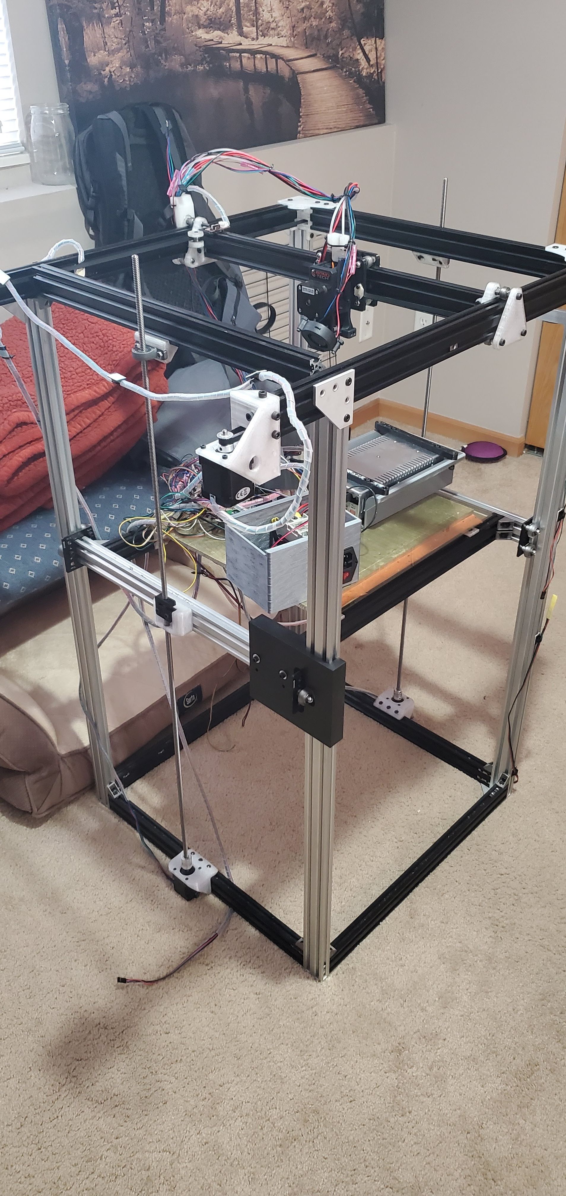
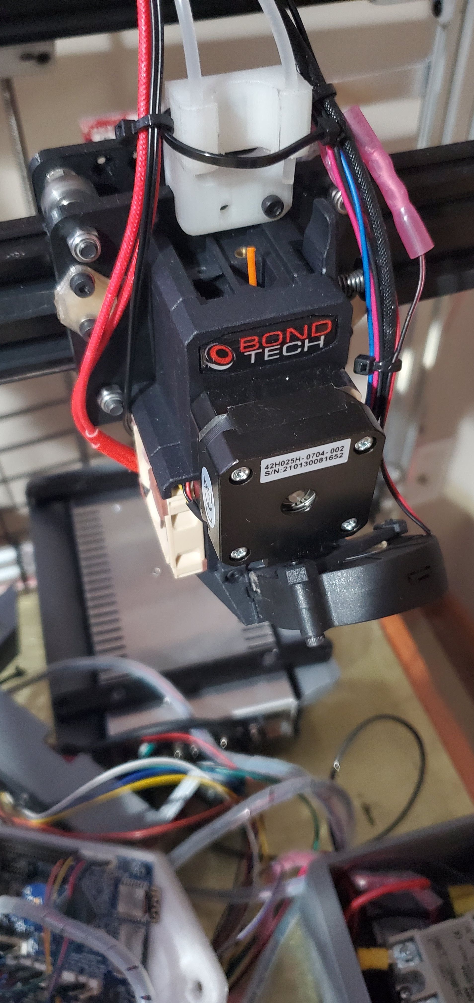
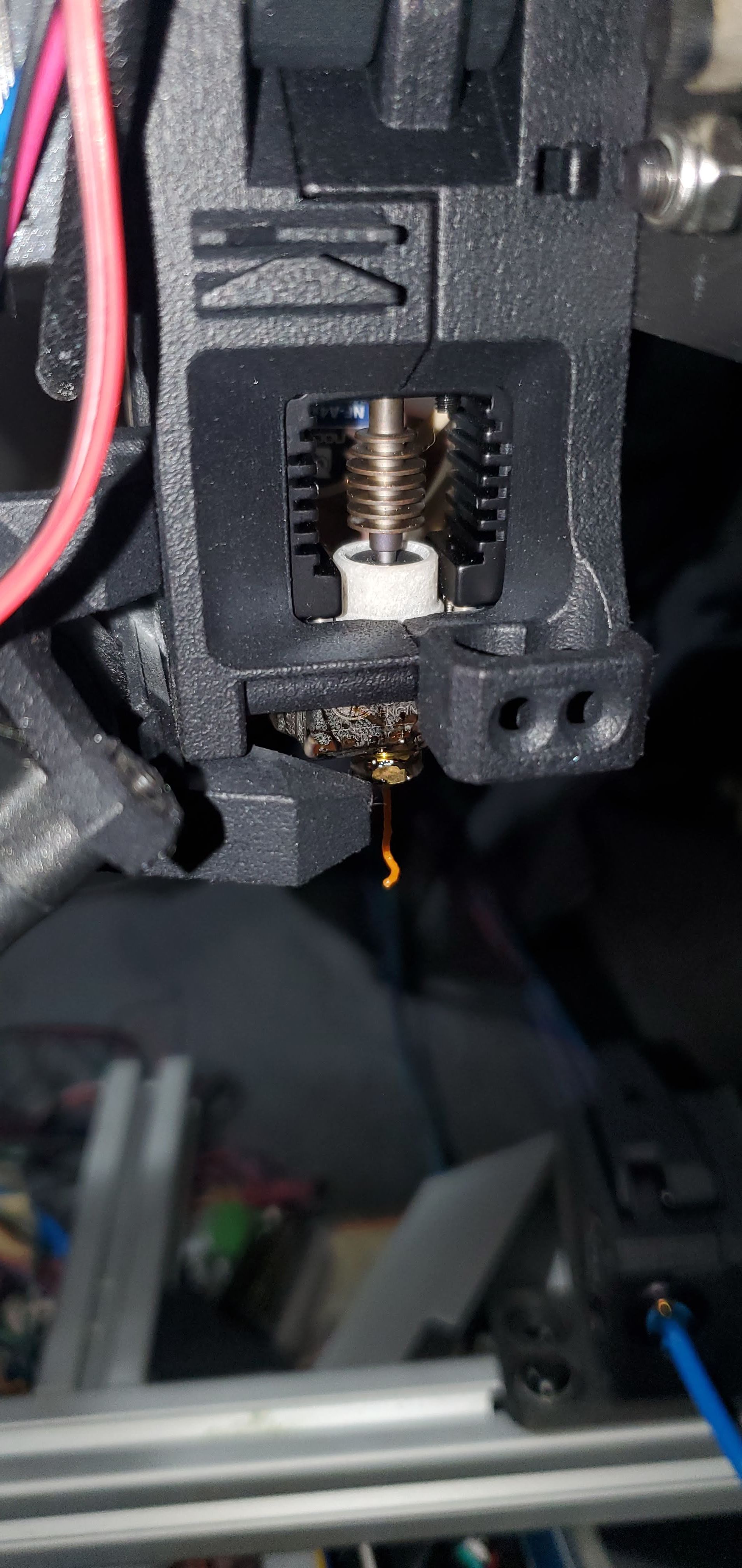
      Long story short this printer started life about 4 years ago with our old 3DP manager, he never really finished it, the guys that took over the department toiled about 500 hours into it, bought a beautiful bond tech extruder and mosquito magnum hot end and never got it to print reliably. I picked it up for way less than a trip to the grocery store ("for parts") and originally had visions of pulling all the best components off for a voron build and leaving it's skeletal remains. But the last 2 weeks of research now has me pointed pointed me to saving this big boy (once I figured out where the inspiration for it's design came from) and trying to root cause it's issues.

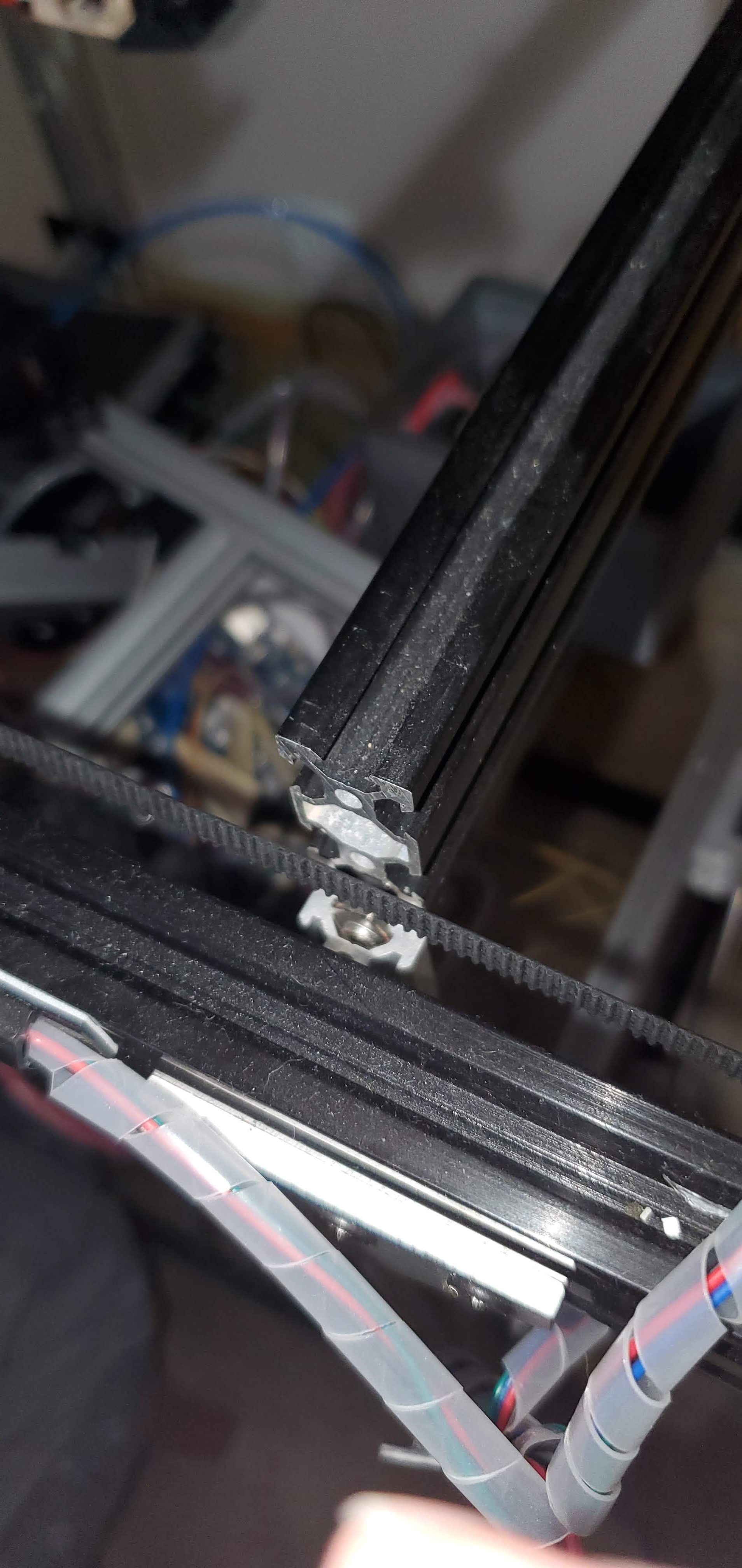
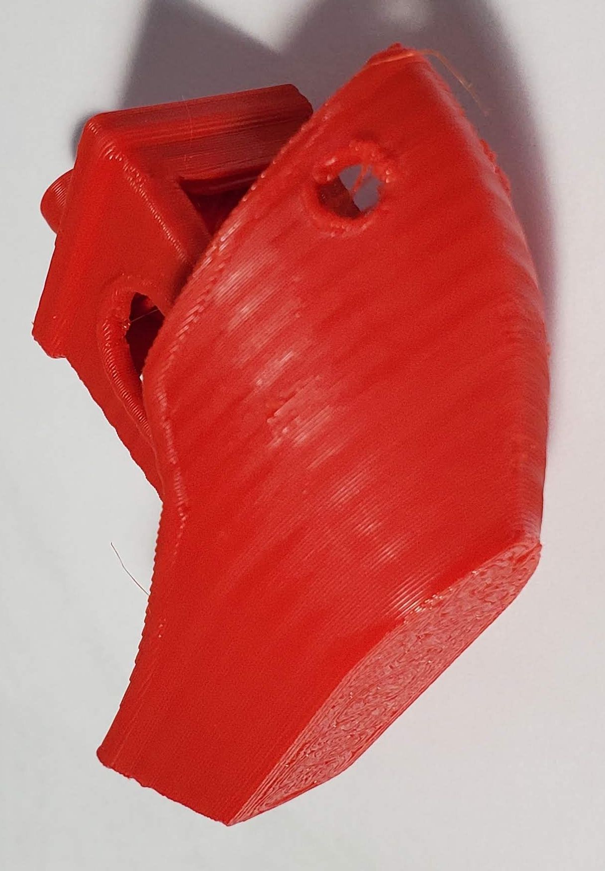
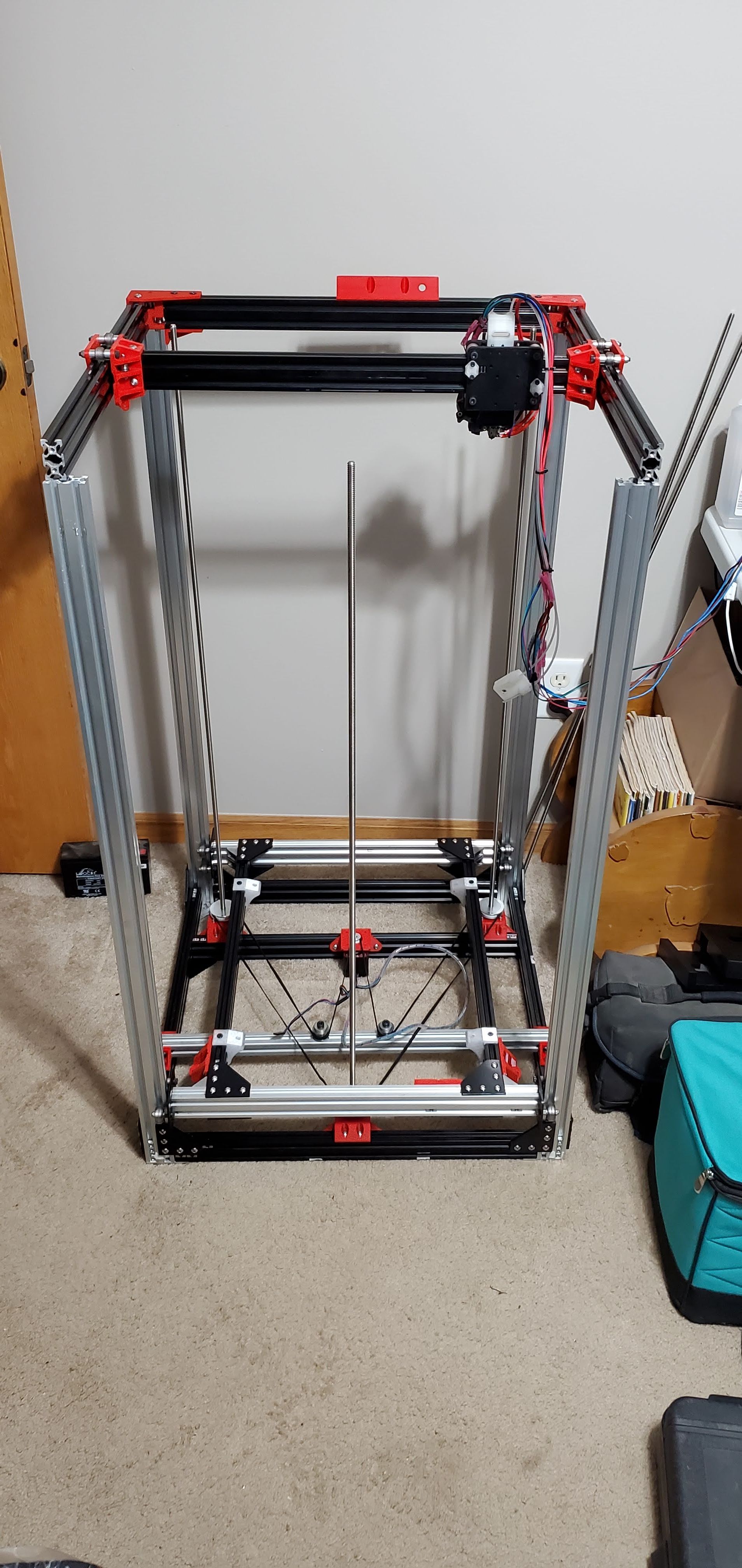
      I'm brand new to these printers, but my first thought is that the Z is too tall to every be reliable. The bug that they never figured out was at some point the printer would either skip a step or the extruder would slip and it would make the best looking bowl of spaghetti you've ever seen over night. My assumption is that at this point, the extruder should be reasonably reliable with this set up, but I'm not sure the best way to monitor or debug this particular problem. I'm thinking of setting up a longer print, affix a dial indicator to the frame in view of a camera to monitor the Z movements and just let it run. When it starts making spaghetti, I can review the footage and see if I can pick up any sort of skip, stall etc. But I'm open to ideas and asking for any help anyone can provide.

      TLDR; I think this beast can be saved. My first thought is halve the Z height (unless I can get it running as is), add a 3rd lead screw (ala Phaedrux 3 screw mod) and possibly redo the wheel mounts with the 3 wheel mods that seem to be very popular.

      20220314_185208.jpg 20220314_185314.jpg 20220314_191659.jpg 20220314_192135.jpg 20220314_192206.jpg

      posted in My Duet controlled machine d-bot troubleshooting
      imadunaticundefined
      imadunatic