@ajlapp Looks like M42 is the correct direction
Posts made by ajlapp
-
RE: Bed and/or hot end over temp signalposted in Duet Hardware and wiring
-
RE: Bed and/or hot end over temp signalposted in Duet Hardware and wiring
@dc42 <quote>defining a GPIO pin as a thermostatically-controlled fan</quote>
Any insight into how to define this? It's not clear to me. Thanks.
-
RE: Bed and/or hot end over temp signalposted in Duet Hardware and wiring
Thanks for the quick reply.
My thought was to bring in the Duet pin and a secondary pin and OR them into a master shutoff.
-
Bed and/or hot end over temp signalposted in Duet Hardware and wiring
Is there currently a usable DIO or other physical signal that is trigger by a hot end or bend over temp?
I’m looking to add a secondary safety system to my printer that cuts main power if there is a thermal runaway.
I’d like to use the signals coming from the Duet as part of the system if they’re accessible.
-
RE: Large Volume Printer - The Beastposted in My Duet controlled machine
Linear Rails
https://www.amazon.com/gp/aw/d/B06VVXT19J?psc=1&ref=ppx_pop_mob_b_asin_titleBall Screw
https://www.amazon.com/gp/aw/d/B01LXZTNRY?psc=1&ref=ppx_pop_mob_b_asin_titleThe frame is thick wall steel square tubing with a pad welded to one face. That face was machined flat with the bearing blocks mounts and other features all in one shot.
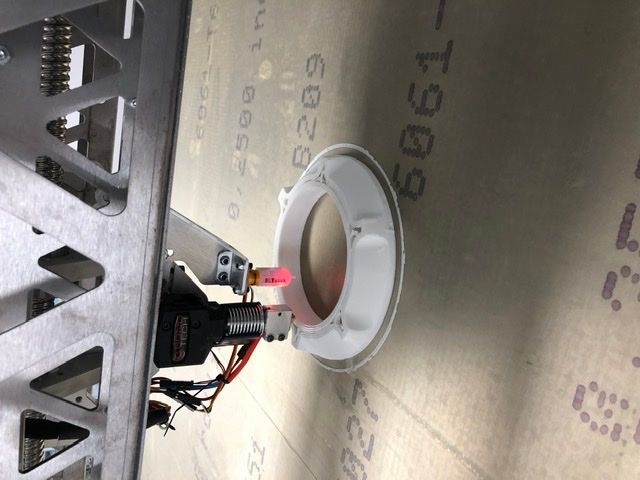
I’m using a E3D Volcan with a 1.2mm nozzle and 3mm PLA for now.
We had a project planned for this that has since dried up so for now we’ll just be using it as a general printer.
-
RE: Large Volume Printer - The Beastposted in My Duet controlled machine
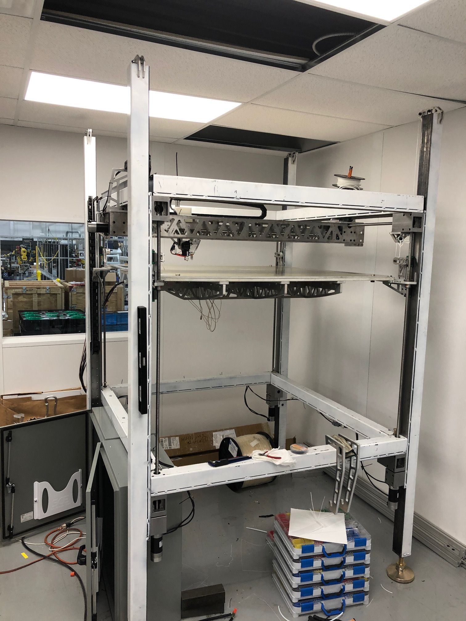
@JRDM I built all axis identical. Same screw, same bearing blocks, same rail and same motor.
This was partially out of economy of scale and simplicity.
I wanted to keep all the motor mounts/bearing blocks identical. These same machined blocks set the frame rails...everything is machined and pinned.
The beefy motors paid off in the end...the table weight really swelled as the build progressed. It was stiff enough to start and the stiffening structure got heavy on accident.
We eventually added counter-balance weights...you can see the strings and pulley assemblies at the corners.
Anyway, the table needs to be re-imagined to cut weight.
My only other regret was building it so tall. We wanted to fit the control cabinets underneath. But now it’s too tall to see the bed at the start of the print.
All of the linear motion components and servos were sourced from Amazon...approx. $800 per actuator.
-
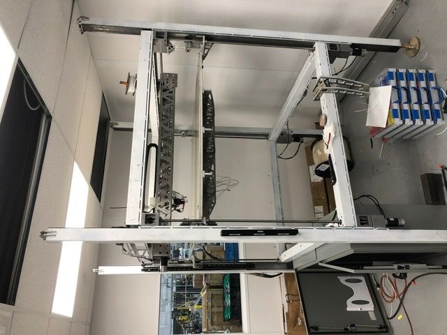
Large Volume Printer - The Beastposted in My Duet controlled machine
So far so good...finally got my large volume printer up and running.
-Duet Control board
-4 independent z-axis screws
-THK style linear rails
-matched axis...all 7 use the same BLDC servo and actuator components
-Heated bed-1m^3 total print volume
We still need some additional thermal controls before we can start the long prints.


-
RE: Stop Z from going beyond 0posted in My Duet controlled machine
Ha! Why do I have my M208 set to Z-780??

 ️
️This would have saved my buns twice now.....I never even saw that.
X and Y are set correctly...go figure.
Been working on this beast sporadically for almost a year...should be printing this week finally. Mind the mess and dangling wires!

-
Stop Z from going beyond 0posted in My Duet controlled machine
Is it possible to force the machine to not go beyond 0 on the z axis?
On a few occasions now we've crashed the bed into the nozzle and other equipment because the manual jog controls will allow the machine to go into the negative Z space.
Normally this isn't too big a deal but on our large volume machine the z-axis screws are very powerful and a lot of damage occurs.
Anyway, a soft z-stop would really help me out but I can't seem to find a setting for this.
Worst case we'll go to hard stops but that has its own issues.
Thanks.
-
RE: M303 failure and other heater problemsposted in Duet Hardware and wiring
Working! 24v and the thermistor line in config did the trick.
-
RE: M303 failure and other heater problemsposted in Duet Hardware and wiring
It’s definitely a 24v...so I’ll update that and my thermistor info.
Thanks.
-
RE: M303 failure and other heater problemsposted in Duet Hardware and wiring
That’s for the bed...yes it’s correct and it does work. I haven’t tried the bed heater yet but I know the thermocouple is working.
For the extruder heater I’m now thinking that this is a power issue...the heater is likely a 24v unit...so I probably just need to juice the board voltage.
Maybe?!?
-
M303 failure and other heater problemsposted in Duet Hardware and wiring
Just getting around to turning on heaters on this custom build...I'm using a filastrude volcano tip with their supplied heating element and thermistor.
I was getting heater faults because of slow temp rise so I tried an M303 but that crapped out around 100 degrees C and said that it was cancelled because it did not meet the desired temp.
This is my first outing with these types of heaters so I'm a bit lost. I have the extruder heater on E0 and the thermistor on E0. I have a fan wired up but I disconnected for now because I wasn't sure if it was a factor.
I'm running the Duet at 12v currently.
CONFIG BELOW
; Configuration file for Duet WiFi (firmware version 1.21)
; executed by the firmware on start-up
;
; generated by RepRapFirmware Configuration Tool v2 on Wed Jan 16 2019 13:17:53 GMT-0500 (Eastern Standard Time); General preferences
G90 ; Send absolute coordinates...
M83 ; ...but relative extruder moves; Network
M550 P"AAM_Large_Volume_Printer" ; Set machine name
M551 P"password: ; Set password
M552 P10.0.0.55 S1 ; Enable network and set IP address
M553 P255.255.255.0 ; Set netmask
M554 P192.168.1.254 ; Set gateway
M586 P0 S1 ; Enable HTTP
M586 P1 S0 ; Disable FTP
M586 P2 S0 ; Disable Telnet;X Drive
M584 X5 ; map drive 5 to X axis...both actuators use the same pulse train
M92 X400 ; set steps/mm for X axis
M569 P5 S0 T8.5:8.5:50.0:67.0 ; set drive timings for drive 5 (first drive on breakout board);Y Drive
M584 Y6 ; map drive 6 to Y axis
M92 Y400 ; set steps/mm for Y axis
M569 P6 S0 T8.5:8.5:50.0:67.0 ; set drive timings for drive 6 (second drive on breakout board);Z Drive
M584 Z7:9:10:11 S1 ; map drive 7, 8, 9, 10 to Z axis
M671 X-232.537:-232.537:1291.463:1291.463 Y-202.3872:1169.2128:1169.2128:-202.3872 S8.0 ; define leadscrew locations
M92 Z400 ; Set steps/mm for Z axis
M569 P7:9:10:11 S1 T8.5:8.5:50.0:67.0 ; set drive timings for drive 7,8,9,10; Drives
M569 P1 S1 ; Drive 1 goes forwards
M569 P2 S1 ; Drive 2 goes forwards
M569 P3 S1 ; Drive 3 goes forwardsM566 X500.00 Y500.00 Z20.00 E120.00 ; Set maximum instantaneous speed changes (mm/min)
M203 X30000.00 Y30000.00 Z1000.00 E1200.00 ; Set maximum speeds (mm/min)
M201 X500.00 Y500.00 Z25.00 E250.00 ; Set accelerations (mm/s^2)
M906 X2000.00 Y2000.00 Z2000.00 E800.00 I30 ; Set motor currents (mA) and motor idle factor in per cent
M84 S30 ; Set idle timeout; Axis Limits
M208 X0 Y0 S1 ; Set axis minima
M208 X1000 Y1000 S0 ; Set axis maximaM208 Z0 S1 ; Set axis minima
M208 Z700 S0 ; Set axis maxima; Endstops
M574 X1 S1 ;
M574 Y1 S1 ; Set active high endstops; Z-Probe
M574 Z1 S1 ; Set endstops controlled by probe
M558 P5 H5 F750 T4000 X0 Y0 Z1 ; Set Z probe type/mode 5. H=Dive Height. F=Speed the bed moves
G31 P25 X-29.9974 Y6.5 Z2.4 ; Z probe trigger value, offset in relation to nozzle. And trigger height adjustment
M557 X50:950 Y50:950 S50 ; Define mesh grid; Heaters
;M305 P0 T100000 B4138 R4700 ; Set thermistor + ADC parameters for heater 0
M305 P0 X151 T"J"
M143 H0 S120 ; Set temperature limit for heater 0 to 120C
M305 P1 T100000 B4138 R4700 ; Set thermistor + ADC parameters for heater 1
M143 H1 S280 ; Set temperature limit for heater 1 to 280C
M570 H1 P30 T15 ;allow extruder heater 30 seconds to get to temp....keep temp within 15 degrees
M307 H7 A-1 C-1 D-1 ; Disable the 7th Heater to free up PWM channel 5 on the Duex board.; Fans
M106 P0 S0.3 I0 F500 H-1 ; Set fan 0 value, PWM signal inversion and frequency. Thermostatic control is turned off
M106 P1 S1 I0 F500 H1 T45 ; Set fan 1 value, PWM signal inversion and frequency. Thermostatic control is turned on; Tools
M563 P0 D0 H1 ; Define tool 0
G10 P0 X0 Y0 Z0 ; Set tool 0 axis offsets
G10 P0 R0 S0 ; Set initial tool 0 active and standby temperatures to 0C; Automatic saving after power loss is not enabled
; Custom settings are not configured
-
RE: Leadshine BLM57180 Not Achieving Max Speedposted in General Discussion
Touche...Looks like I need a faster screw or faster external driver.
-
Leadshine BLM57180 Not Achieving Max Speedposted in General Discussion
Now that I finally have my external brushless servos working....thanks everyone on the forum....I'm not achieving max motor speed.
These motors are rated for 3000RPM and should be able to hit 4000RPM max. The motor has a 1000 line encoder and is driving a 10mm pitch ball screw.
With quadrature decoding my steps/mm are 400.
Max Speed = (3000RPM * 4000steps/rev) / 400 steps/mm = 30,000 mm/min = 500mm/s
I have my axis set as such with M203 set to 30,000.
When I run the actuator I on;y hit about 100-125mm/sec.
Am I hitting a limit because of the slow timing needed for these external steppers?
Config
; Configuration file for Duet WiFi (firmware version 1.21)
; executed by the firmware on start-up
;
; generated by RepRapFirmware Configuration Tool v2 on Wed Jan 16 2019 13:17:53 GMT-0500 (Eastern Standard Time); General preferences
G90 ; Send absolute coordinates...
M83 ; ...but relative extruder moves; Network
M550 P"AAM_Large_Volume_Printer" ; Set machine name
M551 P"password: ; Set password
M552 P10.0.0.55 S1 ; Enable network and set IP address
M553 P255.255.255.0 ; Set netmask
M554 P192.168.1.254 ; Set gateway
M586 P0 S1 ; Enable HTTP
M586 P1 S0 ; Disable FTP
M586 P2 S0 ; Disable TelnetM584 X5:6 ; map drive 5:6 to X axis
M92 X400 ; set steps/mm for X axis (drive 5 & 6)
M569 P5 S0 T8.5:8.5:50.0:67.0 ; set drive timings for drive 5 (first drive on breakout board)
M569 P6 S0 T8.5:8.5:50.0:67.0 ; set drive timings for drive 6 (second drive on breakout board); Drives
M569 P1 S1 ; Drive 1 goes forwards
M569 P2 S1 ; Drive 2 goes forwards
M569 P3 S1 ; Drive 3 goes forwardsM92 Y80.00 Z4000.00 E400.00 ; Set steps per mm
M566 X30000.00 Y900.00 Z12.00 E120.00 ; Set maximum instantaneous speed changes (mm/min)
M203 X30000.00 Y6000.00 Z180.00 E1200.00 ; Set maximum speeds (mm/min)
M201 X30000.00 Y500.00 Z20.00 E250.00 ; Set accelerations (mm/s^2)
M906 X2000.00 Y800.00 Z800.00 E800.00 I30 ; Set motor currents (mA) and motor idle factor in per cent
M84 S30 ; Set idle timeout; Axis Limits
M208 X0 Y0 Z0 S1 ; Set axis minima
M208 X762 Y1000 Z1000 S0 ; Set axis maxima; Endstops
M574 X1 Y1 S0 ; Set active high endstops; Z-Probe
M574 Z1 S2 ; Set endstops controlled by probe
M558 P1 H5 F120 T6000 ; Set Z probe type to unmodulated and the dive height + speeds
G31 P500 X0 Y0 Z2.5 ; Set Z probe trigger value, offset and trigger height
M557 X15:0 Y15:195 S20 ; Define mesh grid; Heaters
M305 P0 T100000 B4138 R4700 ; Set thermistor + ADC parameters for heater 0
M143 H0 S120 ; Set temperature limit for heater 0 to 120C
M305 P1 T100000 B4138 R4700 ; Set thermistor + ADC parameters for heater 1
M143 H1 S280 ; Set temperature limit for heater 1 to 280C; Fans
M106 P0 S0.3 I0 F500 H-1 ; Set fan 0 value, PWM signal inversion and frequency. Thermostatic control is turned off
M106 P1 S1 I0 F500 H1 T45 ; Set fan 1 value, PWM signal inversion and frequency. Thermostatic control is turned on; Tools
M563 P0 D0 H1 ; Define tool 0
G10 P0 X0 Y0 Z0 ; Set tool 0 axis offsets
G10 P0 R0 S0 ; Set initial tool 0 active and standby temperatures to 0C; Heaters
M305 P0 X151 T"J"; Automatic saving after power loss is not enabled
; Custom settings are not configured
-
RE: Leadshine BLM57180 Servosposted in Duet Hardware and wiring
I think both of those are workable solutions.
I should be operational sometime next week.
I’ll load some pics once the magic starts.
Thanks again.
-
RE: Leadshine BLM57180 Servosposted in Duet Hardware and wiring
Solved
For one axis anyways...
I've always had the ACS806 wired directly into the stepper motor 4-pin connection....this was doing something so it seemed correct to me.
Anyway, I saw in the docs that the "expansion board" had dedicated pins for Step and Direction....so I wired directly to these pins on the 50-pin expansion port and it works perfectly.
So now my question is...can I wire to the 4-pin ports and can I ultimately use P0, P1 and P2? I have seven actuators and an extruder on this machine.
Thanks for all the help so far!
-
RE: Leadshine BLM57180 Servosposted in Duet Hardware and wiring
Config below. Ultimately I'm hoping to use two of these BLM57180 servos for the X axis. All of my testing had been completed with the servo connected to P0...the config below is me trying to switch to P5.
; Configuration file for Duet WiFi (firmware version 1.21)
; executed by the firmware on start-up
;
; generated by RepRapFirmware Configuration Tool v2 on Wed Jan 16 2019 13:17:53 GMT-0500 (Eastern Standard Time); General preferences
G90 ; Send absolute coordinates...
M83 ; ...but relative extruder moves; Network
M550 P"AAM_Large_Volume_Printer" ; Set machine name
M551 P"password: ; Set password
M552 P10.0.0.55 S1 ; Enable network and set IP address
M553 P255.255.255.0 ; Set netmask
M554 P192.168.1.254 ; Set gateway
M586 P0 S1 ; Enable HTTP
M586 P1 S0 ; Disable FTP
M586 P2 S0 ; Disable TelnetM584 X0:5 Y1 Z2 E4;
; Drives
M569 P1 S1 ; Drive 1 goes forwards
M569 P2 S1 ; Drive 2 goes forwards
M569 P3 S1 ; Drive 3 goes forwardsM569 P5 S0 T8.5:8.5:50.0:67.0 D0 ; Drive 0 goes forwards M569 P0 S0 T8.5:8.5:50.0:67.0 D0
M92 X400.00 ;M92 Y80.00 Z4000.00 E400.00 ; Set steps per mm
M566 X6000.00 Y900.00 Z12.00 E120.00 ; Set maximum instantaneous speed changes (mm/min)
M203 X30000.00 Y6000.00 Z180.00 E1200.00 ; Set maximum speeds (mm/min)
M201 X500.00 Y500.00 Z20.00 E250.00 ; Set accelerations (mm/s^2)
M906 X2000.00 Y800.00 Z800.00 E800.00 I30 ; Set motor currents (mA) and motor idle factor in per cent
M84 S30 ; Set idle timeout; Axis Limits
M208 X0 Y0 Z0 S1 ; Set axis minima
M208 X1000 Y1000 Z1000 S0 ; Set axis maxima; Endstops
M574 X1 Y1 S0 ; Set active high endstops; Z-Probe
M574 Z1 S2 ; Set endstops controlled by probe
M558 P1 H5 F120 T6000 ; Set Z probe type to unmodulated and the dive height + speeds
G31 P500 X0 Y0 Z2.5 ; Set Z probe trigger value, offset and trigger height
M557 X15:0 Y15:195 S20 ; Define mesh grid; Heaters
M305 P0 T100000 B4138 R4700 ; Set thermistor + ADC parameters for heater 0
M143 H0 S120 ; Set temperature limit for heater 0 to 120C
M305 P1 T100000 B4138 R4700 ; Set thermistor + ADC parameters for heater 1
M143 H1 S280 ; Set temperature limit for heater 1 to 280C; Fans
M106 P0 S0.3 I0 F500 H-1 ; Set fan 0 value, PWM signal inversion and frequency. Thermostatic control is turned off
M106 P1 S1 I0 F500 H1 T45 ; Set fan 1 value, PWM signal inversion and frequency. Thermostatic control is turned on; Tools
M563 P0 D0 H1 ; Define tool 0
G10 P0 X0 Y0 Z0 ; Set tool 0 axis offsets
G10 P0 R0 S0 ; Set initial tool 0 active and standby temperatures to 0C; Heaters
M305 P0 X151 T"J"; Automatic saving after power loss is not enabled
; Custom settings are not configured
-
RE: Leadshine BLM57180 Servosposted in Duet Hardware and wiring
I assume I still use M92 to set steps/mm....how does that look? Is P5 then referenced as E2?
M92 E2:5000; Something like this?
-
RE: Leadshine BLM57180 Servosposted in Duet Hardware and wiring
Yes, I've tried extending the timing...my commands look like this currently:
M569 P0 S0 T8.5:8.5:50.0:67.0 D0
M350 X1 I0
M92 X400.00Currently the motor moves but isn't consistent between clockwise and counter-clockwise rotation. Also it's clear to me what the actual steps/mm will be.
The BLM motor states that it has a 1000 line encoder. My ball screw is 10mm pitch...so one revolution will yield 10mm of travel. My initial guess is that the 1000 line encoder actually yields 4000 counts in quadrature. So 400 steps/mm.
This doesn't produce very favorable results...so now I've switched to this:
M569 P0 S0 T8.5:8.5:50.0:67.0 D0 ; Drive 0 goes forwards
M350 X16 I1 ; Configure microstepping with interpolation
M92 X14000.00 ;This drives pretty good, but doesn't turn a consistent amount in CW/CCW. The steps/mm are just a swag...I'm just using trial and error.
It's also very slow.