@droftarts
well i kinda gave up and used configuration tool and extracted code related to fan and heater and it started to work majically so i think problem was some where in letter configuration lol
so now it looks like it wokring for fan parts at least ")
Posts made by alexus
-
RE: Part Cooling Fan on Duex5posted in Duet Hardware and wiring
-
RE: Part Cooling Fan on Duex5posted in Duet Hardware and wiring
@Phaedrux
interesting observation: when i disconnected tthermistor part cooling starts to spin on duex.fan4 port though speed control does not work. So port should be operable -
RE: thermistor wrong readingsposted in Duet Hardware and wiring
@jay_s_uk
tried thta, on one heter of same make gives me now 23C (while other same version heter reads 14C) room tem 24C, i guesss one is just broken some how -
RE: thermistor wrong readingsposted in Duet Hardware and wiring
@jay_s_uk
let me try see what happens -
RE: Part Cooling Fan on Duex5posted in Duet Hardware and wiring
@Phaedrux
nope fun4 does not work either
-
RE: Part Cooling Fan on Duex5posted in Duet Hardware and wiring
@Phaedrux
heh yea i just looked up documentation and yes always on worjs so we know fan works lolwell let me try to assign say fan4 port see what happens
-
RE: Part Cooling Fan on Duex5posted in Duet Hardware and wiring
@Phaedrux which port is always on? also whats output voltage?
-
thermistor wrong readingsposted in Duet Hardware and wiring
hey all so i swaped my hot ends and started getting problmes
i got 2 like this off ebay
https://www.aliexpress.us/item/3256806701760110.html?spm=a2g0o.productlist.main.27.4ea41360HwRQ2G&algo_pvid=828dff27-bf60-44c9-9b1c-851dcaadfca8&algo_exp_id=828dff27-bf60-44c9-9b1c-851dcaadfca8-13&pdp_npi=4%40dis!USD!25.20!14.11!!!25.20!14.11!%402101c59117299097222521575e5491!12000038625165262!sea!US!131197733!ACX&curPageLogUid=xR8vU2bpIqhf&utparam-url=scene%3Asearch|query_from%3Apage sat 104gt which is 100kOhm once, i noticed my headbed on idle shows now 24C and my hotend 14C , room temp 22C on wall so i guess 24C is ok but no way 14C
measured resitance was like 300KOhm, i have other cermatic core i swaped to that restance was 150k and i adjsuted B value to 4390 so now measurmet is 22.8C which is better i think but thats on another modue.... whats a chnce that 1st one that was reading 14c is burned out?
does not look like i can swap termistor on that thing -
RE: Part Cooling Fan on Duex5posted in Duet Hardware and wiring
so debuging futher to hardware level now
on GUI ive set fan 40% and VIN shows i have 24V on Duet2 board,....when i measure voltage on Duex5 Fan3 port i get nothing there while Duex5 VIN has 24v measured, also Fan jumper is set to VIN
what could be wrong here? i tried fan speed 100% and no change
-
RE: Part Cooling Fan on Duex5posted in Duet Hardware and wiring
@droftarts said in Part Cooling Fan on Duex5:
; Fans
; Fan 0 - print cooling
M950 F0 C"duex.fan3" Q500 ; create fan 0 on pin fan0 and set its frequency //10.25.2024 - Used to be "fan0"
M106 P0 S0 H0 ; set value. Thermostatic control is turned off /S-speed 1==100%
; Fan 1 - ToolHeatsink Cooler
M950 F1 C"fan1" Q500 ; create fan 1 on pin fan1 and set its frequency
M106 P1 T36 H1 ; set fan P1 value. Thermostatic control is turned ON for sensor 0 (S0 in M308) H0; Tools
M563 P0 D0 H0 F0 ; define tool 0 (asign F0 as part cooling fan.. used to be F-1)
G10 P0 X0 Y0 Z0 ; set tool 0 axis offsets
G10 P0 R0 S0 ; set initial tool 0 active and standby temperatures to 0Cyea i think thats what i want
-
RE: Part Cooling Fan on Duex5posted in Duet Hardware and wiring
@droftarts
ok so like this and GUI shows "Tool Fan" as name; Fans ; Fan 0 - print cooling M950 F0 C"duex.fan3" Q500 ; create fan 0 on pin fan0 and set its frequency //10.25.2024 - Used to be "fan0" M106 P0 S1 H1 ; set value. Thermostatic control is turned off /S-speed 1==100% ; Fan 1 - ToolHeatsink Cooler M950 F1 C"fan1" Q500 ; create fan 1 on pin fan1 and set its frequency M106 P1 T36 H0 ; set fan P1 value. Thermostatic control is turned ON for sensor 0 (S0 in M308) H0 -
RE: Part Cooling Fan on Duex5posted in Duet Hardware and wiring
@jay_s_uk
if i cange to P1 i ger error
Error in start-up file macro line 103: Fan number 1 not foundassuming u meant to figuration like this?
; Fans ; Fan 0 - print cooling M950 F0 C"duex.fan3" Q500 ; create fan 0 on pin fan0 and set its frequency //10.25.2024 - Used to be "fan0" M106 P1 S1 H1 ; set value. Thermostatic control is turned off /S-speed 1==100% ; Fan 1 - ToolHeatsink Cooler M950 F1 C"fan1" Q500 ; create fan 1 on pin fan1 and set its frequency M106 P0 T36 H0 ; set fan P1 value. Thermostatic control is turned ON for sensor 0 (S0 in M308) H0 ; Tools M563 P0 D0 H0 F0 ; define tool 0 (asign F0 as part cooling fan.. used to be F-1) G10 P0 X0 Y0 Z0 ; set tool 0 axis offsets G10 P0 R0 S0 ; set initial tool 0 active and standby temperatures to 0C -
RE: Part Cooling Fan on Duex5posted in Duet Hardware and wiring
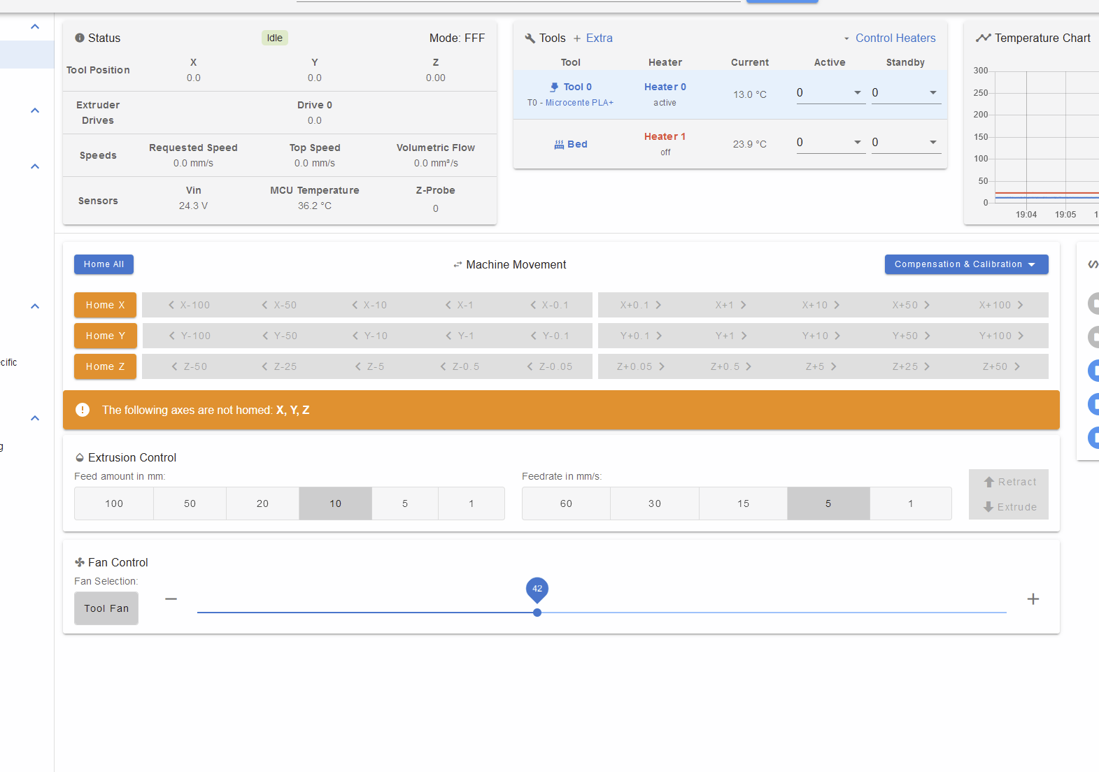
handg on... when i select tool i see GUI changes
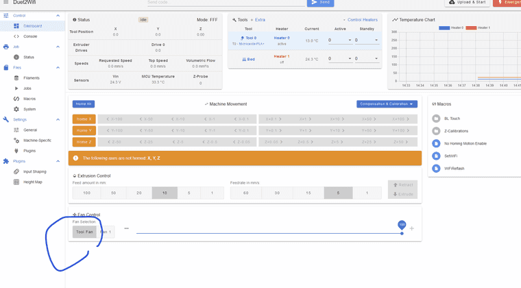
Tool fan is that's a part cooling fan?if so i guess it shows up and now i need to test electrical why it does not spin
-
RE: Part Cooling Fan on Duex5posted in Duet Hardware and wiring
@jay_s_uk
no errors just one waring, i guess tem sensor is off but i assume not related to fan now and will deal with that nextM98 P"config.g" HTTP is enabled on port 80 FTP is disabled TELNET is disabled Warning: Heater 0 predicted maximum temperature at full power is 596°C -
RE: Part Cooling Fan on Duex5posted in Duet Hardware and wiring
@jay_s_uk
some times i wish duet wold be variable name based confir insted of G code, would be much easier to readso i set like this and no availle... also ins P directive set thermostatioc or not?
M950 F0 C"duex.fan3" Q500 ; create fan 0 on pin fan0 and set its frequency //10.25.2024 - Used to be "fan0" M106 P0 S1 H-1 -
Part Cooling Fan on Duex5posted in Duet Hardware and wiring
hey all im trying to setup part cooling fan running off duex5 24V (vin jumpers)
well so far no luck, fan does not even web GUIwhat am i doing wrong?
here is config, fan is connected to duex5 fan3 port... maybe names was chnged?
; Fans ; Fan 0 - print cooling M950 F0 C"duex.fan3" Q500 ; create fan 0 on pin fan0 and set its frequency //10.25.2024 - Used to be "fan0" M106 P0 S1 H0 ; set value. Thermostatic control is turned off /S-speed 1==100% ; Fan 1 - ToolHeatsink Cooler M950 F1 C"fan1" Q500 ; create fan 1 on pin fan1 and set its frequency M106 P0 T36 H0 ; set fan P1 value. Thermostatic control is turned ON for sensor 0 (S0 in M308) H0 ; Tools M563 P0 D0 H0 F0 ; define tool 0 (asign F0 as part cooling fan.. used to be F-1) G10 P0 X0 Y0 Z0 ; set tool 0 axis offsets G10 P0 R0 S0 ; set initial tool 0 active and standby temperatures to 0C -
RE: uniform wave artifact on all printsposted in Tuning and tweaking
@Notepad said in uniform wave artifact on all prints:
WS16
ok so i loosened lead screws and waves got even woth so i think i need to work in makeing sure build plate is stable...
before is did 3Z itwas perrry well i guess let me play with mechanincs and try that adapter tootnx for leading me to right direction
-
RE: uniform wave artifact on all printsposted in Tuning and tweaking
@Notepad
u have some part coming form china now will add it to order and see what happens... i guess i can also make loose ball screw on top that would allow it to be more flexible -
RE: uniform wave artifact on all printsposted in Tuning and tweaking
@Phaedrux
will load file tomorrow, alredy left officebent scew kinda unlikely, 16mm diameter not that easy to bend, also if one is bent it needs to drug 2 others which is harder, and finally if its bent in certain section should artifact change over part height? caz lines stay uniform top to bottom
im thinking to disable mesh compensation and see what happens
-
RE: uniform wave artifact on all printsposted in Tuning and tweaking
@Phaedrux
i turned heated in GUI for full build and waves still there