Filament counters are not working on RC1
Filament counters are not working on RC1
@dc42 yes. There is no issue at all. Works fine with mechanical endstop. It simply doesn't detect sensorless stall so the motor keeps rattling when it hits end
@gloomyandy would you have one ready?
@dc42 can't get to work - max sensitivity of -128, 10% power, different speeds
What would you suggest?
ok, this time it is 1LC issue
trying to do sensorless homing and cannot get it to work - no matter what I do.
Same settings on Mini 5+ - no issues at all.
I have tried to go down to 10% with current while homing
fast speed, low speed - no chages
changed S to values all the way down to -128 - still nothing.
@dc42 is sensorless homing enabled on 3.6.0B3 and RC1?
No need to ask for config file - other axis works just fine with the same homing file and settings.
@Chriss well guess again - I have done fair few of them. no need to be patronising because some other people might have done a lot more than you.
@Chriss regardless how long they last - they are cheap, neat and super easy to replace.
Instead of running bunch of cables and having no quick disconnect option one cable is simpler.
Connectors big? Not sure where you got that
@dc42 @T3P3Tony Mid print
6HC+1LC for toolhead
printer didn't reset
It was still reporting as "Printing" no actions performed
Errror and M122 outputs below
5/02/2025, 00:01:43	Error: Code 7 move error: info=-5.405e+11, seg: s=4294966906 t=4833 d=-540478439424.00 u=-1.1183e+8 a=0.0000e+0 f=08

Debug from 121: Code 7 move error: info=5.319e+11, seg: s=596 t=4294966310 d=531
Debug from 121: 916193792.00 u=0.0000e+0 a=5.7670e-8 f=18

Code 7 move error: in
Debug from 121: fo=-3.424e+11, seg: s=4294966906 t=4833 d=-342447161344.00 u=-7.
Debug from 121: 0856e+7 a=0.0000e+0 f=18

Code 7 move error: info=-1.219e+11, se
Debug from 121: g: s=4443 t=1721 d=-121943228416.00 u=-7.0856e+7 a=0.0000e+0 f=1
Debug from 121: 8

Code 7 move error: info=-6.753e+10, seg: s=6164 t=953 d=-6752
Debug from 121: 5804032.00 u=-7.0856e+7 a=0.0000e+0 f=18
m122
=== Diagnostics ===
RepRapFirmware for Duet 3 MB6HC version 3.6.0-beta.4 (2025-02-11 09:51:22) running on Duet 3 MB6HC v1.02 or 1.02a (standalone mode)
Board ID: 08DLM-9K6R1-L8MSJ-6JTDD-3S46N-TDW1N
Used output buffers: 1 of 40 (34 max)
=== RTOS ===
Static ram: 137396
Dynamic ram: 128312 of which 0 recycled
Never used RAM 62436, free system stack 108 words
Tasks: NETWORK(1,ready,30.3%,169) ETHERNET(5,nWait 7,0.1%,311) HEAT(3,nWait 6,0.0%,323) Move(4,invalid,1.2%,213) TMC(4,nWait 6,3.1%,341) CanReceiv(6,nWait 1,0.0%,598) CanSender(5,nWait 7,0.1%,325) CanClock(7,delaying,0.0%,348) MAIN(1,running,65.0%,103) IDLE(0,ready,0.0%,29) USBD(3,blocked,0.0%,144), total 100.0%
Owned mutexes:
=== Platform ===
Last reset 15:03:33 ago, cause: power up
Last software reset at 2025-02-24 13:31, reason: User, Gcodes spinning, available RAM 77616, slot 0
Software reset code 0x0003 HFSR 0x00000000 CFSR 0x00000000 ICSR 0x00400000 BFAR 0x00000000 SP 0x00000000 Task MAIN Freestk 0 n/a
=== Storage ===
Free file entries: 19
SD card 0 detected, interface speed: 25.0MBytes/sec
SD card longest read time 4.0ms, write time 63.4ms, max retries 0
=== Move ===
Segments created 663, maxWait 509874ms, bed comp in use: mesh, height map offset 0.000, hiccups added 0/0 (0.00/354.03ms), max steps late 1, ebfmin 0.00, ebfmax 0.00
Pos req/act/dcf: 20680.00/20359/-1.00 22193.00/21761/-1.00 237834.00/237833/0.76
Next step interrupt due in 243 ticks, disabled
Driver 0: standstill, SG min 0, mspos 1016, reads 29400, writes 1082 timeouts 102
Driver 1: standstill, SG min 0, mspos 488, reads 29409, writes 1073 timeouts 102
Driver 2: standstill, SG min 0, mspos 488, reads 29409, writes 1073 timeouts 102
Driver 3: standstill, SG min 0, mspos 136, reads 29401, writes 1081 timeouts 102
Driver 4: standstill, SG min 0, mspos 888, reads 29401, writes 1081 timeouts 102
Driver 5: standstill, SG min n/a, mspos 8, reads 29426, writes 1056 timeouts 102
Phase step loop runtime (us): min=0, max=225, frequency (Hz): min=476, max=46875
=== DDARing 0 ===
Scheduled moves 2821376, completed 2821317, LaErrors 0, Underruns [0, 0, 0]
Segments left 1, axes/extruders owned 0x80000007, drives owned 0x80000007
Code queue is empty
=== DDARing 1 ===
Scheduled moves 0, completed 0, LaErrors 0, Underruns [0, 0, 0]
Segments left 0, axes/extruders owned 0x00000000, drives owned 0x00000000
Code queue is empty
=== Heat ===
Bed heaters 0 -1 -1 -1 -1 -1 -1 -1 -1 -1 -1 -1, chamber heaters -1 -1 -1 -1 -1 -1 -1 -1, ordering errs 0
=== GCodes ===
Movement locks held by null, null
HTTP is idle in state(s) 0
Telnet is idle in state(s) 0
File is doing "G1 X272.16 Y285.153 E.0023" in state(s) 0
USB is idle in state(s) 0
Aux is idle in state(s) 0
Trigger is idle in state(s) 0
Queue is idle in state(s) 0
LCD is idle in state(s) 0
SBC is idle in state(s) 0
Daemon is idle in state(s) 0
Aux2 is idle in state(s) 0
Autopause is idle in state(s) 0
File2 is idle in state(s) 0
Queue2 is idle in state(s) 0
=== CAN ===
Messages queued 3267068, received 1085162, lost 0, ignored 0, errs 1, boc 0
Longest wait 4ms for reply type 6029, peak Tx sync delay 506, free buffers 50 (min 48), ts 256939/256938/0
Tx timeouts 0,0,0,0,0,0
=== Network ===
Slowest loop: 207.56ms; fastest: 0.03ms
Responder states: MQTT(0) HTTP(0) HTTP(0) HTTP(0) HTTP(0) HTTP(0) HTTP(0) FTP(0) Telnet(0) Telnet(0)
HTTP sessions: 3 of 8
=== Multicast handler ===
Responder is inactive, messages received 0, responses 0
= Ethernet =
Interface state: active
Error counts: 0 0 0 1 0 0
Socket states: 6 6 2 2 2 0 0 0 0
=== WiFi ===
Interface state: disabled
Module is disabled
Failed messages: pending 0, notrdy 0, noresp 0
Socket states: 0 0 0 0 0 0 0 0
@T3P3Tony Nema23 ad additional 750-1000g to the weight 
when the motors are mounted on the axis and they are moving together it is a lot of weight
I was considering using 42mm servo motors with intehrated drivers.
@fcwilt having 6HC instead of the Mini ads no extra benefits. I could go even with 4x 1LC - but what is the point?
@T3P3Tony said in 48V mini 5+:
@Aurimas one option is to use a mini5+ for Z and then 3hc for XY for a large idex maybe using closed loop becomes sensible for XYU
thanks Tony, but it would not work. I need more than the 3 drivers - I need 2 x Y + X + U - so 4 higher voltage motors for the motion, then 4x Z motors and then 2x extruders.
So I think the most cost effective option would be to go with 6HC + Mini +2x 1LC. ")
Complicated - isn't it. Don't do simple
@dc42 z motors are 40mm Nema23 - got no issues with them at all.
Y motos right now are 60mm Nema17 with 80Ncm torque, 2 ohms and 3.3mH
calculator with 24V tops out at 330mm/s and that is exactly what I have obeserved.
with 48V I can go all the way up to 700mm/s before it will top out.
I cannot use Nema23 since the motors move with the axisis and thus they would be way too heavy.
@dc42 thanks a lot for detail explanation.
In my particular application 7 drivers is really handy since I use it on 600x600 and bigger machines with 4x z motors, 2x Y motors at least X and also U axis for idex. Not to mention 2 extruders sitting on 1lc
So realistically I have to either use 6hc +3hc or use 4x1lc for Z and ready of the drivers for the other axis.
Current for me is not an issue. My motors are only 2A rated
It's getting pretty complicated.
When you look at smaller Steppers you have lots of options. When you step into high torque 60mm long Steppers options become limited
Are there any plans to make it happen?
Same system on mini 5+ I was limited to 300mm/s and 5000 acceleration
With 6HC and 48V it was cruising at 400 and 10000. And still it wasn't the limit
@Anon1337 anything above 48V is classified as high voltage and potentially life threatening.
That's why most systems are normally limited to 48V
Hi again
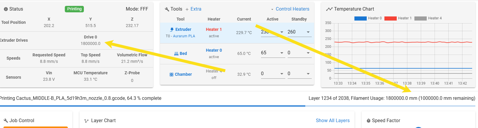
so the setup is 1 tool with 4 heaters.
Tool is setup by assigning multiple heaters to it and it works fine once the temp is set all heaters would heat up and would control the temp.
the problem is that it would not give back control using either M104 or M116 - it just sits there
if the extra heaters are removed it will hand over the control once the heater reaches the temperature.
is there a magic trick to make it work? is it tolerance limits that need to be adjusted - maybe it is not exactly same temperature between the heaters and it is waiting for all of them to match exactly?
@Phaedrux do you know if Speed Factor overrides just the speed or acceleration too? especially m204?
@Phaedrux said in Speed factor doesn't honor M203:
Could you verify in 3.6 beta 4?
printer is running now - thats why I asked if anyone else has the same issue.
3.6.0-beta.2
i know i know it is beta, but before i start changing versions I was just wondering if it is actually the case