Based on the table
https://e3d-online.dozuki.com/Wiki/Thermistor_table
the matching thermistor part number is 104NT-4-R025H42G
https://www.mouser.com/datasheet/2/362/P18-NT-Thermistor-1535133.pdf
Based on the table
https://e3d-online.dozuki.com/Wiki/Thermistor_table
the matching thermistor part number is 104NT-4-R025H42G
https://www.mouser.com/datasheet/2/362/P18-NT-Thermistor-1535133.pdf
The easiest and best method is to match the wire gauge, splice propely, solder the connection and use heat shrink to cover the splice. Use connectors only where needed, typically at the end of the cable where it iterfaces with a board or device. Using a connector to splice on an extension adds another potential point of failure.
Verify firmware version (as requested by dc42).
After some time struggling, I found this to be the best method to set Wifi parameters and successfully join a wireless network.
Verify device is in range of the wifi router
Avoid close proximity to multiple routers and multiple SSIDs
Start a terminal session (YAT) connected via USB
M587 (List ALL stored networks)
If there are any networks listed that you do not want your device to access they need to be removed from the List of Available Networks (M588 gcode)
I removed ALL that were listed. Completely clearing the list.
I had to remove them one by one since the M588 S"*" gcode didn't work for some reason
M588 "what ever net name is there to be removed" (remove network from the stored network list) (MUST be typed verbatim (letter for letter) and inside quotation marks ("))
<<<Edit: M588 S"*" works as expected to remove all networks.>>>
Once the list of stored networks is clean add you wifi network information (M587 gcode)
M587 S"SSID" P"NetPass" (set YOUR network wifi credentials)(MUST be typed verbatim (letter for letter) and inside quotation marks ("))
If the SSID or Password has spaces or funky characters (anything other than 0-1, a-z, A-Z) you may experience issues. Make sure the SSID and Password are typed EXACTLY the same as what the router is expecting. To rule out typos, try changing SSID and Password to something less exotic. Remove spaces and funky characters.
Finally, once the network list is clean (M588) and you have successfully joined the wifi network (M587) Launch network services (M552 gcode)
M552 S1 (launch wifi, Duet will obtain IP address)
The terminal session will display the IP of the Duet, connect to DWC via a browser.
Further reading -
https://duet3d.dozuki.com/Guide/1.)+Getting+Connected+to+your+Duet/7
https://duet3d.dozuki.com/Wiki/Gcode#Section_Quoted_strings
https://duet3d.dozuki.com/Wiki/Gcode#Section_M587_Add_WiFi_host_network_to_remembered_list_or_list_remembered_networks (M588 and M589 also listed)
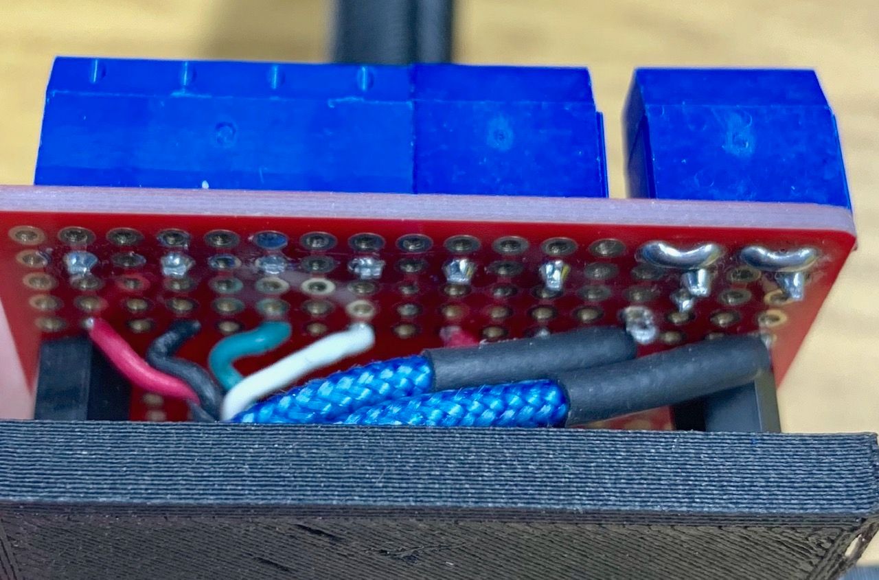
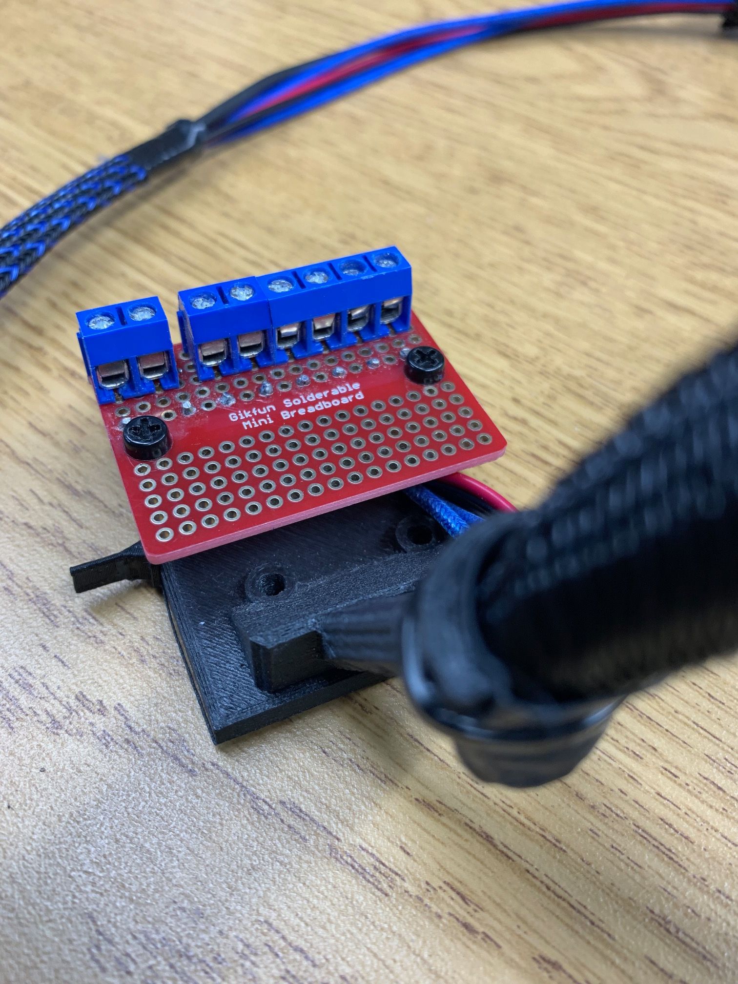
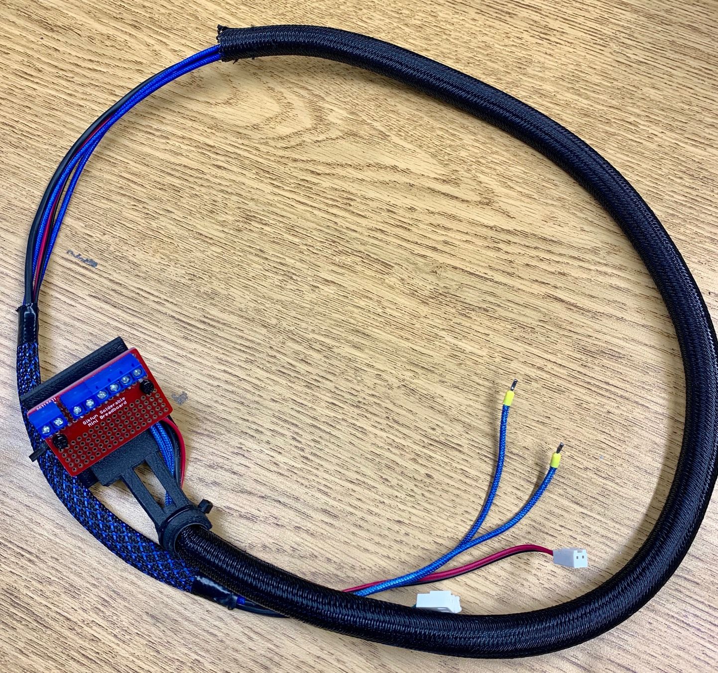
@matt3o Not sure if this would work for you (see pics).


Using extension/adapter cables or adding connectors to a harness adds bulk and creates potential failure points.
I found this method to be the best. If anything needs to be changed, its simple. Supports up to 16 terminal points.
All that's missing is a printed label plaque
I built a delta based on the AKLP spec.
240mm bed
480mm MGN12 type linear rails
Endstop switches are approx 655mm from the build plate
The linear rails start 165mm above the build plate (build plate to top of linear rail 645mm)
I'm using Haydn's 288mm mag diagonal rods, smart effector, PT100, E3D Volcano, Bondtech QR
DUET Duet 2 WiFi/2.04RC3
@dgrat
https://docs.duet3d.com/User_manual/Connecting_hardware/Z_probe_mesh_bed
Partway down under the heading:
Running bed mesh compensation
Establish a Z=0 datum
I believe the Y stepper is not wired correctly.
From Duet Literature:
Identifying the stepper motor phases
Here are two ways you can pair the stepper motor wires into phases:
Use a multimeter. There should be a few ohms resistance between two wires that belong to the same phase, and no continuity between wires that belong to different phases.
With the motor wires not connected, spin the spindle between your fingers. Short two of the wires together, then spin the spindle again. If it is much harder to spin than before, those two wires belong to the same phase. Otherwise, try again with a different pair of wires shorted together.
I installed a Smart Effector a few months ago, it really works well. I don't believe there is a better overall solution. It's an easy install and has been reliable since day one. There is no hotend offset and it uses the nozzle as the probe. It replaces the tedious process of manual calibration, with better results, from a push of a button. I run auto calibration twice (takes about a minute) and I'm ready to print. The only issue that I encountered was one of the mag arms popping off due to buildup between the magnet and ball. The sockets and balls need to be cleaned periodically. If I was to add a bed sensor to my non delta printers it would be the same type of sensor, hopefully there will be a non delta solution as well.
Another E3D blog post - 9/28/21
https://e3d-online.com/blogs/news/rapidchangerevo
I have a delta that is the same spec as the anycubic kossel linear plus. I am using Haydn 288 rods with a smart effector, volcano hotend and the stock E3d hot end fan. For the part cooling fan I use one like this https://www.thingiverse.com/thing:2808152.
The setup works extremely well.
https://duet3d.dozuki.com/Guide/2.)+Wiring+your+Duet+2+WiFi-Ethernet/9
Top right corner of the DUET board in the image shows jumper placement.
I'm posting my config.g file contents for reference. The only original parts from the Anycubic are the bed and the linear rails/blocks so I wouldn't try to use the file as is on your machine.
I 'm using a Duet2 Wifi board, the parameters/settings I believe are the same for the Maestro.
; General preferences
G90 ; Send absolute coordinates...
M83 ; ...but relative extruder moves
;M665 R133.969 L272.869 B110 H287.79 ; Set delta radius, diagonal rod length, printable radius and homed height
;M666 X0 Y0 Z0 ; Put your endstop adjustments here, or let auto calibration find them
M665 L288 R138 H304.65 B110.0 X0 Y0 Z0
M666 X0 Y00 Z0 A0.00 B0.00
; Network
M550 PDelta2 ; Set machine name
M552 S1
M552 S1 ; Enable network
M587 S"" P"" ; Configure access point and IP addresses. You can delete this line once connected
M586 P0 S1 ; Enable HTTP
M586 P1 S0 ; Disable FTP
M586 P2 S0 ; Disable Telnet
; Drives
M569 P0 S1 ; Drive 0 goes forwards
M569 P1 S1 ; Drive 1 goes forwards
M569 P2 S1 ; Drive 2 goes forwards
M569 P3 S1 ; Drive 3 goes forwards
M350 X16 Y16 Z16 E16 I1 ; Configure microstepping with interpolation
M92 X80 Y80 Z80 E475 ; Set steps per mm
M566 X1000 Y1000 Z1000 E300 ; Set maximum instantaneous speed changes (mm/min)
M203 X18000 Y18000 Z18000 E3600 ; Set maximum speeds (mm/min)
M201 X3000 Y3000 Z3000 E3000 ; Set accelerations (mm/s^2)
M906 X1500 Y1500 Z1500 E1000 I30 ; Set motor currents (mA) and motor idle factor in per cent
M84 S60 ; Set idle timeout
; Axis Limits
M208 Z0 S1 ; Set minimum Z
; Endstops
M574 X2 Y2 Z2 S1 ; Set active high endstops
; Z-Probe
M558 P5 R0.4 F600
G31 P100 X0 Y0 Z -0.1 ; Set Z probe trigger value, offset and trigger height
M557 R80 S20 ; Define mesh grid
; Heaters
M305 P0 T100000 B4138 C0 R4700 ; Set thermistor + ADC parameters for heater 0
M143 H0 S120 ; Set temperature limit for heater 0 to 120C
M305 P1 X200 ; Set thermistor + ADC parameters for heater 1
M143 H1 S320 ; Set temperature limit for heater 1 to 280C5
; Fans
M106 P0 S0.3 I0 F500 H-1 ; Set fan 0 value, PWM signal inversion and frequency. Thermostatic control is turned off
M106 P1 S1 I0 F500 H1 T45 ; Set fan 1 value, PWM signal inversion and frequency. Thermostatic control is turned on
M106 P2 S1 I0 F500 H1 T45 ; Set fan 2 value, PWM signal inversion and frequency. Thermostatic control is turned on
; Tools
M563 P0 D0 H1 ; Define tool 0
G10 P0 X0 Y0 Z0 ; Set tool 0 axis offsets
G10 P0 R0 S0 ; Set initial tool 0 active and standby temperatures to 0C
; Automatic saving after power loss is not enabled
; Custom settings are not configured
; Miscellaneous
M501
T0
@Dz Can you elaborate on how you came to the conclusion that there are many DUET Wifi owners that are experiencing Wifi issues? I have 6 machines all running on DUET Wifi boards for over a year and have not once had an issue related to the Wifi Module or the hardware in general.
@ErlerPrint3D said in Read Voltage from Heatbed Power IN:
M308 S18
Ths sounds like what you need.
Bnnn The temperature or other value when the ADC output is zero
Cnnn The temperature or other value when the ADC output is full scale
Reference:
https://docs.duet3d.com/User_manual/Reference/Gcodes#m308-set-or-report-sensor-parameters
Additional parameters for linear analog sensors
Fn F0 = unfiltered (fast response), F1 = filtered (slower response, but noise reduced and ADC oversampling used to increase resolution). F1 is only available when using a port intended for thermistors, not when using a general input port.
Bnnn The temperature or other value when the ADC output is zero
Cnnn The temperature or other value when the ADC output is full scale
@p1ngb4ck I believe there is an 8.5 mm height difference between the V-6 and the volcano
A short to ground error is never good, recheck wiring, test the board with known good motor and cable. Change only one item at a time to limit variables while diagnosing.
Test the coils on the V2S without the cable plugged in, if you are measuring across the correct pin pairs (or pair of pins for each coil) then the resistance measurement should be the same on both coils.
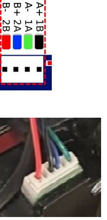
I checked the one I have and both coils measure about same 3.6-3.7 ohms. I believe I had to swap pins around on the motor side, not sure. I uploaded a pic of connections/colors/pairs I am using. Hopefully this helps. The motor you have may not match exactly, consistency with parts from the far east is always suspect.
