I sounds like motors not correctly wired to the board. Make sure that the coils are correctly paired...
Best posts made by FelixH
-
RE: Need some help with workbee cncposted in CNC
-
RE: True Bed Leveling (G32) leads to "inconsistent Z probe readings"posted in General Discussion
@gloomyandy yeah, got you! As I already checked, by setting the tolerance to 0.004 it did already the trick.
thanks a lot!
-
RE: Trigger height not taking effect on Delta printer.posted in Tuning and tweaking
Well, I did change the trigger height to 16.25 and re-run the delta calibration. The Delta Height changed by 0.2mm (or so). I approached the nozzle to the bed until Z=0 and, sure enough, I got nice paper grab...
Thanks a lot, everybody
-
RE: CNC style Pendantposted in Hardware wishlist
Yesterday I noticed something weird while using the pendant. The multiplier knob was set at x10 and, not thinking about it, I tried to move the Z axis. Because I turned the wheel too much, I got a message on the display telling me to chill out (paraphrasing here) because I wanted to move more than the axis allows. So far, so good. However the X axis moved a little bit instead, even though the Z axis was selected on the axis knob. Now that's weird. Once I switched to x0.1 multiplier, the Z axis moved ok.
Knowing that, I'll be more careful from now on, but I am really curious if this is a "global" bug or it is just me.I am using an Arduino Nano and I changed the resistor on it in order for the bypass of the display to work. The Arduino Pro Micro I ordered came when the Pendant was already assembled, so I saw no reason to open it up again. Also, I did not update the firmware to the latest version, as I understood it was only Pro Micro related and I didn't see a point on doing it.
Cheers!
-
RE: CNC and Coordinate Systemsposted in CNC
Well, I finally got the time to do some experimenting. If I understood that correctly, I was mistaken regarding the G10 command. It seems it's like this:
P1 is G54 (WCS #1)
P2 is G55 (WCS #2)
etc. -
RE: Do we need ABL (Auto Bed Leveling) devices anymore?posted in General Discussion
The closest thing I‘ve seen similar to what would be using Stall detection as a Z probe is the Smart Effector on a Delta. It is not the same, as it is based in some other phenomenon, but you effectively use the nozzle tip a sensor. Maybe one could design a carriage for a cartesian printer this this technology??
BTW, buying the Smart Effector for my Delta was one of the best decisions I‘ve done (3D Printing related, that is).
-
RE: Famous error :Warning: motor phase A Drive1posted in Duet Hardware and wiring
aren't you missing something?. The error tells you exactly what is happening. Instead of looking to your config files, check the continuity of you motor cables. I got this error once and it pop up because one of the motor cables was pinch by the printer's frame and eventually was severed. I repaired the cable and everything was fine.
-
RE: Sensorless homing tuning on cartesian printerposted in Tuning and tweaking
Well, i mixed the code on the 3 independent homing files into one homeall.g file (see below). It appears to work without any issues...
I hope this post helps somebody else with similar issues.
Thanks a lot, everyone.
; homeall.g ; called to home all axes ;M98 Phomex.g ;M98 Phomey.g ;M98 Phomez.g G91 ; set relative mode G1 S2 Z5 F1200 ; lift Z G29 S2 ; to clear the height map before Z homing M561 ;reset bed compensation ; homex.g G1 S2 X0.2 ; Move X by 0.2 mm, clear stall status M400 ; make sure everything has stopped before we make changes M913 X60 ; X motor % current M915 X S2 R0 F0 ; set X sensitivity, do nothing when stall, unfiltered M574 X1 S3 ; set endstops to use motor stall G1 S1 X-220 F3600 ; move X back, stopping at the end stop M400 ; make sure everything has stopped M913 X100 ; XY motors to 100% current M915 X S30 R0 F0 ; set X sensitivity high, do nothing when stall, unfiltered M400; ; make sure everything has stopped ; homey.g G1 S2 Y0.2 ; Move Y by 0.2 mm, clear stall status M913 Y75 ; Y motor % current M915 Y S3 R0 F0 ; set X sensitivity, do nothing when stall, unfiltered M574 Y S3 ; set endstops to use motor stall G1 S1 Y-220 F3600 ; move X back, stopping at the end stop M400 ; make sure everything has stopped M913 Y100 ; XY motors to 100% current M915 Y S30 R0 F0 ; set Y sensitivity high, pause when stall, filtered M400; ; make sure everything has stopped homez.g G90 ; absolute positioning G1 X110 Y110 F6000 ; go to first probe point G30 ; home Z by probing the bed -
RE: SuperPID Spindle Controller with Duet WiFi v2.xposted in CNC
So, as promised the following is what I've done to get my SuperPID working flawlessly with my Duet Wifi 2.
The wiring schematic is as follows (please don't mind the inaccuracy of standard symbols):

The ON/OFF is accomplished using the FAN0 (-) pin to ground the RUN port on the SuperPID.
The router RPM of the router is controlled by the (-) pin of the FAN1.On the config.g file on the Duet a file named customconfig.g is called in which customizations are done without modifying the main config.g file. On this file I added the following lines, which configure the FAN1 as the "Tool 0" pin and set the RPM for a max PWM signal (255). It also inverts the PWM signal, so that the more PWM the more RPM:
M106 P1 I-1 H-1 A21 ; disable FAN2 & allocate Tool 0 to pin 21
M563 P0 S"Spindle" ;
M453 S"Spindle" P21 I1 T0 R30000; , Tool 0 = Spindle, invert PWM, 30000 RPM at max PWM
To turn ON the router:
M106 P0 S255To turn OFF the router:
M107 P0To set the RPMs:
M3 S15000 ; Set the router speed at 15000 RPM (PWM aprox 128)References:
-
RE: Tool missing after update to firmware 3.3posted in General Discussion
@JoergS5 thanks, T0 is at the very end of the config.g file, not shown on the snippet above.
@jay_s_uk that seems to have been the issue, apparently. I added the example line shown on the wiki and it appears to work ok:
M584 X0 Y1 Z2:3 E4:5:6I wonder why did it work without that line previously...
Latest posts made by FelixH
-
RE: Component U3 on a Duet WiFi 2posted in Duet Hardware and wiring
@droftarts ok, so a 5v voltage regulator. Makes total sense that the board doesn't work if it is broken. I will try to get a replacement and hope for the best
thanks!
-
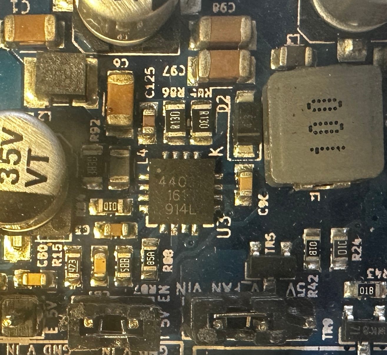
Component U3 on a Duet WiFi 2posted in Duet Hardware and wiring
Hi all,
recently a Duet WiFi 2 Board died on me (full disclosure, a clone board). I traced the problem down to the component U3, which was getting really hot when powering the board with USB (with Vin, the board was totally dead).
Does somebody know what this component does and if I could get a replacement somewhere?
Thanks in advance!
-
RE: Y axis moves on wrong direction when homing after power cycleposted in Tuning and tweaking
for the life of me, I cannot understand what is going on here.
After having a look at the thread I posted, I got my printer homing perfectly every single time. I was so happy. here is my homey.g file:
; homey.g
; called to home the Y axis


M913 Y70               ; drop motor current to 70%
G4 P100                ; wait 100ms

M915 Y S-3 R0 F0 	     ; set Y sensitivity, do nothing when stall, unfiltered
G4 P100                  ; wait 100ms
M400                     ; wait for current moves to finish


G91 					; set relative movements
G1 H2 Z5 F1200 		    ; lift Z

; tune drivers                     ; relative positioning
G1 H2 Y0.4 F3000         ; power up motors to ensure they are not stalled
G4 P100                  ; wait 100ms
M400                     ; wait for current moves to finish


; home Y
G1 H1 Y5 F1200    		; move slowly away
G1 H1 Y-300 F6000 		; move to Y axis endstop and stop there (first pass) ; eren 3600
G1 Y5 F1200       		; go back a few mm
G1 H1 Y-10 F6000  		; move to Y axis endstop once more (second pass) ; eren 3000
G1 Y10 F1200      		; go back a few mm
M400              		; wait for current moves to finish


M913 Y100              	; restore motor current to 100%
G4 P100                	; wait 100ms

G1 H2 Z-5 F1200 		; reset Z
G90						; reset absolute movements
Now, I came yesterday from my winter break. Today I wanted to try a new method of steps calibration I though out. I moved the printer over the bench so I can have better access to it (the calibration involves having a pen attached to the extruder, a piece of paper and so on).
I start up the printer and I home it. The Y homing starts failing miserably again in the same fashion it did before.
I cannot understand how come it worked perfectly before, I change absolutely nothing at all and starts failing again. It did work perfectly. Nice homing, nice prints, reliable... and all of the sudden it stopped working again.
Any insights?
-
RE: Duet 3 Mini 5+ sensorless homing configurationposted in Tuning and tweaking
I am very thankful I found this thread because I was having the very same issue and, after some experimenting with your scripts it works better for me too now.
However, I do have a question: why there is no M915 command on these routines? I assume if ignored it assumes a certain value lie S3??
I mean, I tried with and without M915 and it works, so... I am confused, somehow
-
RE: Y axis moves on wrong direction when homing after power cycleposted in Tuning and tweaking
well, I just found this post here which has some insightful info:
https://forum.duet3d.com/topic/20622/duet-3-mini-5-sensorless-homing-configuration
I will have a look later this afternoon and report back.
-
RE: Y axis moves on wrong direction when homing after power cycleposted in Tuning and tweaking
@gloomyandy I actually set it to 200. I experimented with higher but since there was no change I left it at 200.
I will experiment further this afternoon
-
RE: Y axis moves on wrong direction when homing after power cycleposted in Tuning and tweaking
@gloomyandy I changed the H parameter. I actually calculated the value with the formula I found in the documentation, which gave me around 130 as minimum speed.
I did not yet tried to add the M400/G4 commands. I had yesterday so many things going on, I completely forgot.
What I wanted to mention, however is that the homeall.g files is diferent because if I just call the diferent macros for each axis, the z is lifted three times instead of just the one. Just a matter of elegance for me
-
RE: Y axis moves on wrong direction when homing after power cycleposted in Tuning and tweaking
@gloomyandy thanks for your response. I already did play quite a bit with the M913 value (% current) as well as the M915 S parameter (sensitivity). I have been playing even more for the last hour. I see no improvement on my part. I have the impression the M915 S parameter does absolutely nothing. It makes no difference if I set it to -10 or +25, the Y axis does not work correctly.
However, I found an example configuration on the documentation in which a second pass is used for homing. I added this and in the first pass, the Y stalls immediately but the second pass goes all the way to the back end of the printer, which is good. Just for kicks I added a third pass, so I have the benefit of having two good passes for setting the Y-home.
I will have to live with it until I learn more about this.
On a related topic, I will have a read to setting the drivers correctly. On the first print tests the results are quite underwhelming. More precisely, I have been having problems with the extrusion in which as soon as the model has some gap where retraction has to be done, it begins to underextrude or something similar. I have check every hardware issue and I am confident that it is not a hardware problem at all. So I will look if there is something I left when configuring the drivers.
-
RE: Y axis moves on wrong direction when homing after power cycleposted in Tuning and tweaking
@fcwilt I have 2 other machines with Duets and Sensoreless homing. Not an issue whatsoever...
-
Y axis moves on wrong direction when homing after power cycleposted in Tuning and tweaking
Hi all,
on this third installment of the ongoing series featuring my last printer, today I bring you a weird issue.
The printer I'm trying to set up is a cartesian powered by an original Duet 3 Mini 5+ WiFi. I set up the firmware manually by comparing my other printers and some examples I found in internet, since this is my first Duet 3 board.
A part from some issues due to new-to-me features, I thought the printer was well setup. The motors do move along the correct directions, the fans do work, etc. Homing X and Y works sensorless.
However there is still something that eludes me:
after a power cycle, whenever I try to home the Y axis it has a weird behavior depending on how I do it:
- If I hit "Home All" on the web interface or send a G32 command, the Y axis moves towards me, so in the opposite direction.
- If I hit "Home Y" on the web interface in moves just a tiny bit to the home position and then it sets itself as homed.
The only workaround I found to be able to home all 3 axis and keep tuning the printer is to do a "Home Y", then move the Y -50mm (towards me), and then home again. If I do a "Home all" after that, it homes without an issue.
here is my config files:
config.g
; Configuration file for Duet WiFi (firmware version 3.11)
; executed by the firmware on start-up


;##### General preferences

G90                                                ; Send absolute coordinates...
M83                                                ; ...but relative extruder moves
M550 P"Black Bear"								   ; set printer name

;#####  PanelDue Display

M575 P1 S1 B57600

; Network
M552 S1                                            ; Enable network
M586 P0 S1                                         ; Enable HTTP
M586 P1 S0                                         ; Disable FTP
M586 P2 S0                                         ; Disable Telnet


;##### Drives

M569 P1 S1 D3 V10                                  ; Drive 1 (X) goes Backwards
M569 P2 S1 D3 V10                                  ; Drive 2 (Y) goes backwards

M569 P0 S1 D3 V100                                 ; Drive 0 (Z left) goes forwards
M569 P4 S0 D3 V100                                 ; Drive 4 (Z right) goes forwards

M569 P3 S1 D3 V0                                   ; Drive 3 (E) goes backwards

M584 X1 Y2 Z0:4 E3   							   ; Drivers mapping

M671 X-45:314 Y0:0 S5                             ; define dual driven z-axis

M350 X16 Y16 Z16 E16 I1                           ; Configure microstepping with interpolation
M92  X99.36 Y100.16 Z400.00 E424                  ; Set steps per mm
M566 X600.00 Y600.00 Z48.00 E300       	          ; Set maximum instantaneous speed changes (mm/min)
M203 X8000.00 Y8000.00 Z720.00 E3600 	          ; Set maximum speeds (mm/min)
M201 X1500.00 Y1500.00 Z100.00 E10000 	          ; Set accelerations (mm/s^2)
M906 X750.00 Y750.00 Z600.00 E800.00 I30  	      ; Set motor currents (mA) and motor idle factor in per cent

M84 S30 										   ; Set idle timeout


;##### Axis Limits

M208 X-15.0 Y-47.3 Z0 S1                            ; Set axis minima
M208 X250 Y210 Z210 S0                             ; Set axis maxima


;##### Endstops

M574 X1 S3                                         ; Motor Stall X Endstop
M574 Y1 S3                                         ; Motor Stall Y Endstop
M574 Z1 S2 										   ; Probe Z Endstop

M915 X Y S30 F0 R0				                   ; Stall guard config when not homing

;##### Pinda Settings

M558 P5 C"io2.in" I1 H1 F1000 T6000 A3			   				; Prusa Pindav2 Probe
M308 S2 P"temp2" A"Pinda V2" Y"thermistor" T100000 				; Pinda thermistor
G31 P1000 X-23 Y7 Z0.54 S21 H2 T0.02				   	       ; Nozzle offset with temperature compensation (0.02mm/°C)

M557 X20:215 Y10:205 P4											; Define mesh grid for probing
M376 H5											   				; Fade heigth 5mm

;##### Bed Heater

M308 S0 P"temp1" Y"thermistor" B4725 C7.060000e-8 	            ; Define thermistor
M950 H0 C"out0" Q25 T0                                          ; Link pin name with heater
M307 H0 R0.250 K0.280:0.000 D11.93 E1.35 S1.00 B0               ; Bed PID
M140 H0								                            ; Links everything on the GUI
M143 H0 S95                                              		; Set temperature limit for heater 0 to 95C


;##### HotEnd Heater

M308 S1 P"temp0" Y"thermistor" B4725 C7.06e-8 R4725                    ; Define thermistor
;M308 S1 P"e0temp" Y"thermistor" T100000 B4725 C7.06e-8 R4725
M950 H1 C"out1" T1						                         ; Link pin name with heater
M307 H1 R2.501 K0.327:0.000 D8.35 E1.35 S1.00 B0 V23.8           ; Hotend Autotune
M143 H1 S260                                      		         ; Set temperature limit for heater 1 to 260C


;##### Fans

;Part cooling fan

M950 F0 C"out3" Q100											; Create fan 0 on pin out3 and set its frequency
M106 P0 S0 H-1													; Set fan 0 value. Thermostatic control is turned off

; Hotend cooling fan

M950 F1 C"out4" Q100											; Create fan 1 on pin out4 and set its frequency
M106 P1 T45 S255 H1											    ; Thermostatic control is turned on at 45°C

; Housing cooling fan

M950 F2 C"out5" Q100											; Create fan 1 on pin out4 and set its frequency
M106 P2 T30 S200 H1											    ; Thermostatic control is turned on at 30°C (when drivers are about to start)

;##### Tool

M563 P0 D0 H1 F0
G10 P0 X0 Y0 Z0
G10 P0 R0 S0
M572 D0 S0.06

T0 								; Select tool
homey.g
; homey.g
; called to home the Y axis


G91						; set relative mode

G1 H2 Y0.2              ; Move Y by 0.2 mm, clear stall status
G29 S2                  ; to clear the height map before Z homing
M561                    ; reset bed compensation

M400 					; make sure everything has stopped before we make changes

M913 Y65 				; Y motor % current
M915 Y S-10 R0 F0 		; set Y sensitivity, do nothing when stall, unfiltered
G1 H2 Z5 F1200 			; lift Z
G1 H1 Y-260 F4800 		; move Y back, stopping at the end stop

M400 					; make sure everything has stopped
M913 Y100 				; XY motors to 100% current

M915 Y S30 R0 F0 		; set Y sensitivity high, pause when stall, filtered

G1 H2 Z-5 F1200         ; reset z
G90 					; back to absolute mode
homeall.y
; homeall.g
; called to home all axes


G91							; set relative mode
G1 H2 Z5 F1200 				; lift Z
G29 S2                  	; to clear the height map before Z homing
M561                    	;reset bed compensation


; homex.g

G1 H2 X0.2              	; Move X by 0.2 mm, clear stall status

M400 						; make sure everything has stopped before we make changes
M913 X70 					; X motor % current
M915 X S-3 R0 F0 			; set X sensitivity, do nothing when stall, unfiltered
;M574 X1 S3 				; set endstops to use motor stall
G1 H1 X-260 F3600 			; move X back, stopping at the end stop

M400 						; make sure everything has stopped
M913 X100 					; XY motors to 100% current

M915 X S30 R0 F0 			; set X sensitivity high, do nothing when stall, unfiltered

M400; 						; make sure everything has stopped


; homey.g


G1 H2 Y0.2              	; Move Y by 0.2 mm, clear stall status


M913 Y65 					; Y motor % current
M915 Y S-10 R0 F0 			; set X sensitivity, do nothing when stall, unfiltered
;M574 Y S3 					; set endstops to use motor stall

G1 H1 Y-260 F4800 			; move Y back, stopping at the end stop

M400 						; make sure everything has stopped
M913 Y100 					; XY motors to 100% current

M915 Y S30 R0 F0 			; set Y sensitivity high, pause when stall, filtered

M400		        		; make sure everything has stopped


;homez.g


G90         	         	; absolute positioning
G1 X125 Y105 F6000 	 		; go to first probe point
G30              	 		; home Z by probing the bed
any kind of help, would be appreciated. I don't really know what I am missing.