Duet3D Logo Duet3D
    • Tags
    • Documentation
    • Order
    • Register
    • Login
    1. Home
    2. jhonf441
    • Profile
    • Following 0
    • Followers 1
    • Topics 17
    • Posts 39
    • Best 1
    • Controversial 0
    • Groups 0

    jhonf441

    @jhonf441

    1
    Reputation
    5
    Profile views
    39
    Posts
    1
    Followers
    0
    Following
    Joined Last Online

    jhonf441 Unfollow Follow

    Best posts made by jhonf441

    • Collaborative pellet extruder test plant

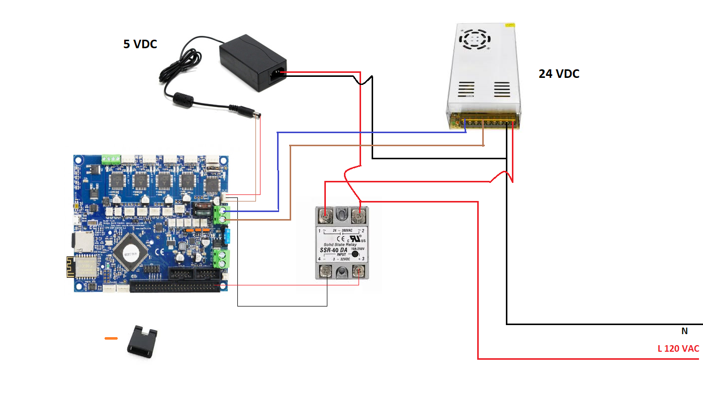
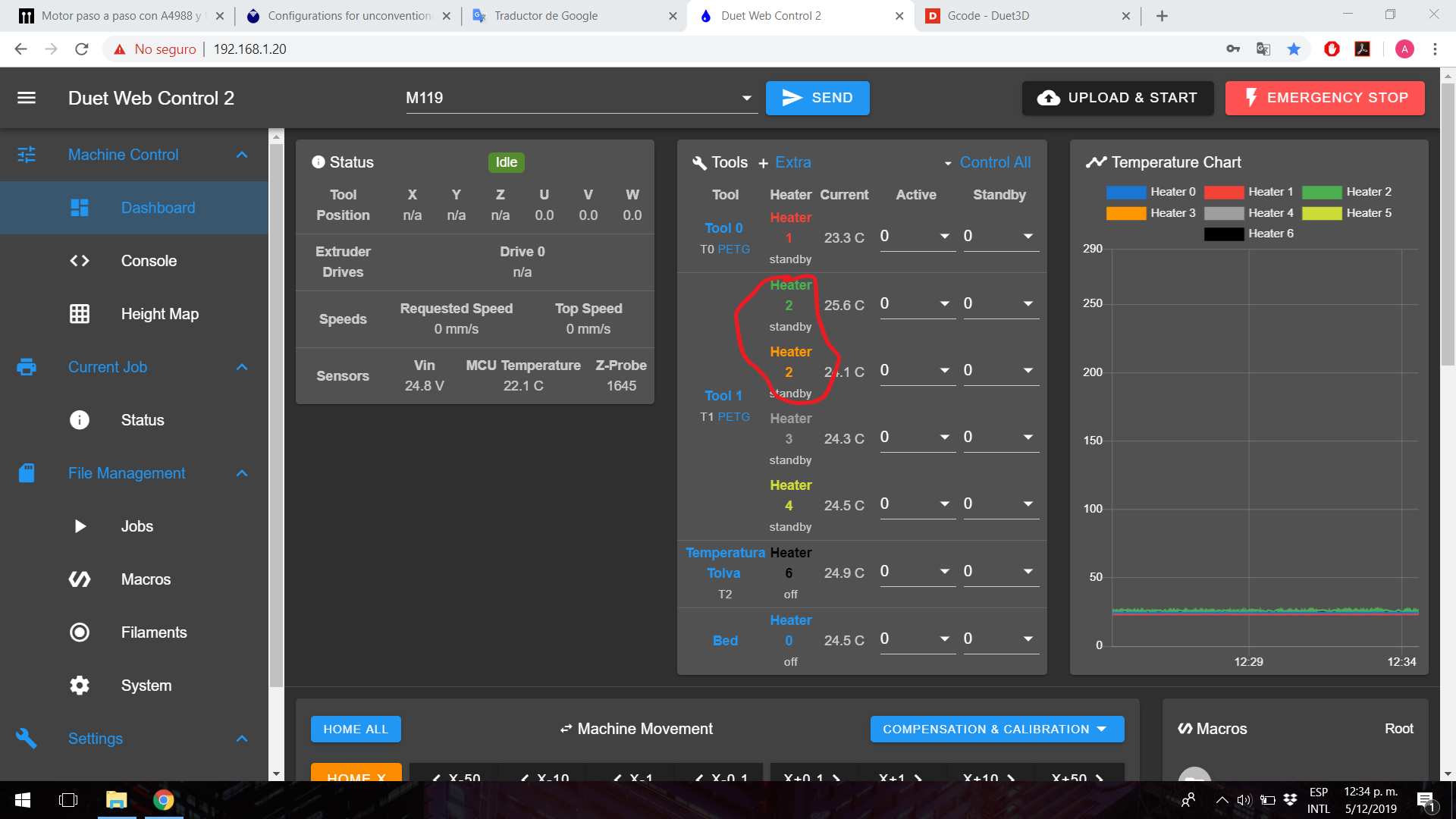
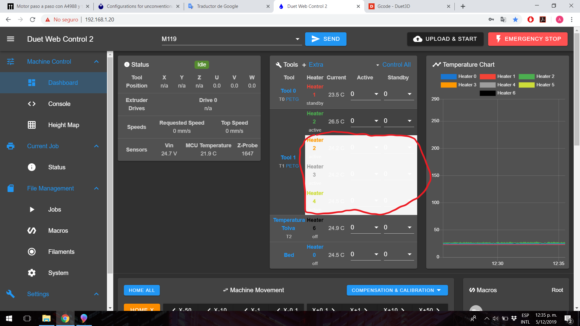
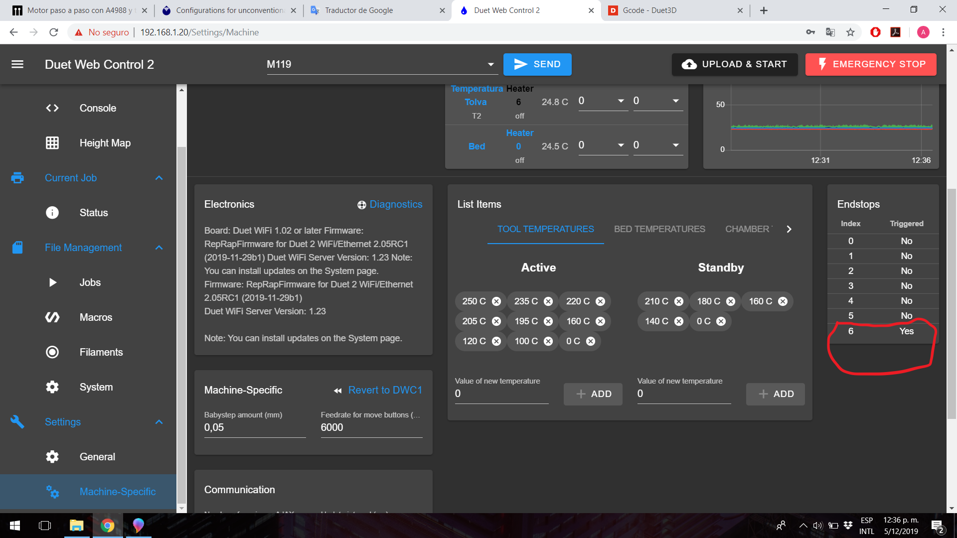
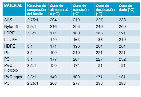
      Hello everyone, I built a pellet extruder and I plan to put it to the test, so it will be available to users to run the tests that occur to them, I hope they help me find the best solution to the problems found in the Road, initially I am testing Polypropylene, the design consists of a nema 23 engine of 2.5Nm of torque, 4.2A, use 48v Dc to power the dq452ma driver, 200 steps / rev and has a 15: 1 speed reducer, use a 460mm full length wood auger and 331mm effective length, I use 4 independent heating zones listed ascending starting at the nozzle, and there is a fifth temperature sensor in the hopper part to monitor the temperature in that area and control the cooling fans, the heaters operate at 110v AC and I use SSR to control them, to calculate the steps per millimeter I have measured the pitch of the auger thread as shown in the attached image of the screw or that measurement gives me a total of 27.3mm so with that data and using x16 micropasses, the steps / mm found are 1758 steps / mm, I have 1.8mm and 2.8mm nozzles, the temperatures are being controlled at the values ​​shown in table 1 for polypropylene (PP).

      0_1566145438333_Screw.png
      0_1566145576815_2019-08-18 (2).png
      Definitions:
      cylinder or sleeve: it is the perforated bar through which the screw or drill passes and it is the one who transfers the heat to the plastic granules

      screw : it is who moves the plastic granules towards the nozzle

      So far I have tried to move the extruder from DWC manually, the temperature is stable and it takes about 10 minutes to reach the temperature with the entire cylinder filled with hard and cold material (polypropylene), the temperature in the part of the hopper, which should be kept as cold as possible, remains at 40 degrees Celsius, the hopper is designed to avoid jams, I'm still looking for an insulating material to wrap the cylinder and prevent some heat from dissipating in the air.

      What worries me now in a preliminary way is that from DWC the highest speed I can send to the engine without losing steps is 10mm / s which seems to be a problem for me, at that speed the amount of material that comes out of the 1.8mm nozzle is very large, but if I'm going to slice an object to send it to print I can't use print speeds greater than 600mm / min because they would cause the extruder to not move due to lack of torque, and according to simplify3d the time of Impression goes from 3 hours using 50mm / s to 6 hours which makes no sense to me.

      as I said is my preliminary observation, so any appreciation or advice in this regard is welcome, I plan to mount an extruder in the printer but I'm a little short of time, by the University, and that will take me some time because I need redesign some parts so that it can support the extruder, I also plan to design a system to vacuum pellet pellets directly from the bulk located to the extruder hopper located about 2 meters high and use some sensor to detect the lack of pellet.

      some prices in dollars on the raw material
      The bulk of transparent polypropylene pellet of transparent color today is 25 kg for 44 dollars

      The pigment bag to give color to the molten pellet costs 4 dollars, weighs 1kg and yields enough to give color to 25kg of pellet

      Attached some photos, if you want to see beyond you can request CAD models or I can disassemble the extruder to a certain part.

      know that there are better motors that can give me more torque and speed, like an AC or DC servomotor, but in this case it is what I had at hand, and I would like to see how feasible this system before making major investments!

      0_1566146484592_IMG_20190818_111844.jpg
      0_1566146689985_IMG_20190818_111857.jpg
      0_1566146826206_IMG_20190818_111915.jpg

      posted in General Discussion pellet extruder tuning
      jhonf441undefined
      jhonf441

    Latest posts made by jhonf441

    • RE: CNC style Pendant

      @FelixH Hello, I don't use pendant but I have noticed that sometimes when I am moving the machine on the Y axis it moves a little on the positive X axis and vice versa

      posted in Hardware wishlist
      jhonf441undefined
      jhonf441
    • RE: can you suggest kinematics for multiple z axis?

      @Phaedrux thanks

      posted in General Discussion
      jhonf441undefined
      jhonf441
    • can you suggest kinematics for multiple z axis?

      Hi, I have a XY core printer with 600mm x 600mm printing area, currently the bed goes up and down, but since the bed is heavy I want to use a real self-leveling and I wanted to know what kinematic couplings they recommend or what they think of an XY core that up and down with the fixed bed.

      I am going to use independent motors with linear guide

      thanks in advance.

      posted in General Discussion
      jhonf441undefined
      jhonf441
    • Tool changer question.

      Hello, I was wondering if it is possible to have a tool changer?, but to have a row of tools in the back and another in the front.

      posted in General Discussion
      jhonf441undefined
      jhonf441
    • RE: Automatic shutdown without ATX

      hi, i have something like this.

      Duet and panelDue remain on after main power is turned off

      cableado.png

      posted in Duet Hardware and wiring
      jhonf441undefined
      jhonf441
    • Strange behavior I don't understand

      i was trying to print and wanted to use micro steps to help adherence but i have noticed and this is not the first time the following

      For example, the first layer and the current one had a height of 0.25mm and I wanted to help with micro steps by decreasing the separation between the bed and the extruder, but since there is no significant change, I reached -0.24mm of micro step and it turns out that the indicated height is z = 0.5mm, what am I missing?
      attached image
      I am using duet wifi with RepRapfirware 2.04, but I have seen that behavior in other firmware versions

      IMG_20200428_221604-min.jpg

      posted in General Discussion
      jhonf441undefined
      jhonf441
    • RE: 3 x Z-Axis - Idea vs Engineering reality

      can you look at this
      https://www.youtube.com/watch?v=a9irK9rOUHY&t=36s

      posted in General Discussion
      jhonf441undefined
      jhonf441
    • RE: Printing Clay at the Resolution of Plastics

      @tom_lauerman hello I would like to know more about the correct calculations to take into account that a 50 mm filament is pushed through a nozzle of approximately 1 mm, how is the calculation?

      posted in My Duet controlled machine
      jhonf441undefined
      jhonf441
    • 7-inch DWC and PanelDue anomalies

      I have the following configuration

      Duet Web Control Version 2.0.4
      FIRMWARE_NAME: RepRapFirmware for Duet 2 WiFi/Ethernet FIRMWARE_VERSION: 2.05RC1 ELECTRONICS: Duet WiFi 1.02 or later FIRMWARE_DATE: 2019-11-29b1

      ; Configuration file for Duet WiFi (firmware version 1.21)
      ; executed by the firmware on start-up
      ;
      ; generated by RepRapFirmware Configuration Tool v2 on Fri Mar 15 2019 23:53:22 GMT-0500 (hora estándar de Colombia)
      
      ; General preferences
      G90                                    		; Send absolute coordinates...
      M83                                     	; ...but relative extruder moves
      G21						; G21 establece las unidades en mm / G20 establece las unidades en pulgadas 
      ; kinematics type
      M669 K1                                		; Select CoreXY mode
      
      ; Network 
      
      
      M552 S1                               	 	; Enable network
      M586 P0 S1                               	; Enable HTTP
      M586 P1 S0                              	; Disable FTP
      M586 P2 S0                               	; Disable  Telnet
      
      ; Drives
      M569 P5 S1                           	 	; Drive 5 goes forwards axis  X
      M569 P6 S0                               	; Drive 6 goes forwards axis Y
      M569 P7 S1                               	; Drive 7 goes forwards Extrusor
      M569 P8 S1                               	; Drive 8 goes forwards Axis z
      M569 P9 S1				 	; Drive 9 goes forwards Axis Z
      M569 P10 S1				 	; Drive 10 goes forwards axis z
      M569 P11 S1 				 	; Drive 11 goes forwards axis z
      M584 X5 Y7 Z8:9:10:11 U9 V10 W11 E6   			; Apply custom drive mapping and four Z motors connected to driver outputs 8, 9, 10 and 11 Z
      M350 X16 Y16 Z16:16:16:16  I1                ; Configure microstepping with interpolation
      M350 E2 
      M350 U16 V16 W16 I1
      M92 X80 Y80 Z400:400:400:400 E311;E2487   E155    E311  	; Set steps per mm
      M92 U400 V400 W400 
      M566 X900 Y900 Z30:30:30:30 E20    	 	; Set maximum instantaneous speed changes (mm/min)
      M566 U30 V30 W30
      M203 X18000 Y18000 Z200:200:200:200 E600  ;E1500	; Set maximum speeds (mm/min)
      M203 U200 V200 W200
      M201 X4000 Y4000 Z100:100:100:100 E100  ;E1000   	; Set accelerations (mm/s^2)
      M201 U100 V100 W100
      M84 S30                                  	; Set idle timeout
      
      ; define posiciones de los tornillos
      M671 X-321:-321:317:317 Y-144:184:184:-144 S4	;agregar parametro F2
      
      ; Axis Limits
      M208 X-267 Y-245 Z0 S1                         	; Set axis minima
      M208 U0 V0 W0 S1
      M208 X267 Y230 Z406 S0                   	; Set axis maxima
      M208 U406 V406 W406 S0
      
      ; Endstops Makerbot Mechanical Endstop v1.2
      M574 X1 Y1 S0                            	; S_ endstop-type: 0 = active low, 1 = active high, 2 = slice-direction-probe, 3 = motor load detection
      ; MicroSiwch
      ;M574 Z1 U1 V1 W1 S1
      M574 Z1 U1 V1 W1 S1


      ; Z-Probe
      ;M574 Z1 S2                               	; Set endstops controlled by probe
      ;M307 H3 A-1 C-1 D-1                             ; Disable heater on PWM channel for BLTouch
      ;M558 P9 H5 F120 T18000 A5 R0.2 B1 		;S0.03   R0.75    Set Z probe type to bltouch and the dive height + speeds
      ;G31 P25 X0 Y33 Z1.13 				; Set Z probe trigger value, offset and trigger height
      ;M557 X-265:265 Y-207:245 S53:113           	;Define mesh grid
      
      ; Heaters
      M305 P0 T100000 B4138 R4700              	; Set thermistor + ADC parameters for heater 0
      M143 H0 S120                             	; Set temperature limit for heater 0 to 120C
      M305 P1 T100000 B4725 C7.060000e-8 R4700        ; Set thermistor + ADC parameters for heater 1
      M143 H1 S250                             	; Set temperature limit for heater 1 to 250C
      M912 P0 S-6.5					; ajuste el calentador 1 ajuste electronico del monitor de temperatura en grados centigrados 
      
      ;m571 consultar
      
      ;Extrusora de tornillo
      M305 P2 T100000 B4100 R4700       ; Set thermistor + ADC parameters for heater 1
      M143 H2 S250                             	; Set temperature limit for heater 1 to 250C
      M305 P3 T100000 B4100 R4700       ; Set thermistor + ADC parameters for heater 1
      M143 H3 S250                             	; Set temperature limit for heater 1 to 250C
      M305 P4 T100000 B4100 R4700        ; Set thermistor + ADC parameters for heater 1
      M143 H4 S250                             	; Set temperature limit for heater 1 to 250C
      M305 P5 T100000 B4100 R4700        ; Set thermistor + ADC parameters for heater 1
      M143 H5 S250                             	; Set temperature limit for heater 1 to 250C
      M305 P6 T100000 B4100 R4700        ; Set thermistor + ADC parameters for heater 1
      M143 H6 S250                             	; Set temperature limit for heater 1 to 250C


      ; Fans
      ;M106 P0 I0; invertir PWM del ventilador 1
      M106 P0 S0 F500 H-1                   		; Set fan 0 value, PWM signal inversion and frequency. Thermostatic control is turned off
      M106 P1 S0 I0 F500 H-1              	; Set fan 1 value, PWM signal inversion and frequency. Thermostatic control is turned on
      M106 P2 S127 I1 F500 H-1                   	; Set fan 2 value, PWM signal inversion and frequency. Thermostatic control is turned off
      
      ; Tools
      M563 P0 D0 H1 S"Extrusora volcano"                       	; Define tool 0
      G10 P0 X0 Y0 Z0                          	; Set tool 0 axis offsets
      G10 P0 R0 S0
      M563 P1 D0 H2:3:4:5 S"Extrusora de Tornillo"  
      G10 P1 X0 Y0 Z0                          	; Set tool 0 axis offsets
      G10 P1 R0:0:0:0 S0:0:0:0                          	; Set initial tool 0 active and standby temperatures to 0C
      M563 P2 H6 S"Temperatura Tolva" 
      G10 P2 X0 Y0 Z0                          	; Set tool 0 axis offsets
      G10 P2 R0 S0
      
      ; Avance de presión unidad extrusora 
      ;M572 D0 S0.06
      
      ; Automatic saving after power loss is not enabled
      M911 S21 R23 P"M913 X0 Y0 G91 M83 G1 Z3 E-5 F1000" ; Set voltage thresholds and actions to run on power loss
      
      ; Custom settings are not configured


      ; activar bltouch
      ;M280 P3 S160 I1 ; Alarm Release and Push-Pin UP
      ;M280 P3 S140 I1; modo 5v logic zmin


      M929 P"eventlog.txt" S1; iniciar el registro en el archivo eventlog.txt
      
      ;LEDs
      ;M307 H4 A-1 C-1 D-1  
      ;M307 H5 A-1 C-1 D-1  
      ;M307 H6 A-1 C-1 D-1
      ;M307 H7 A-1 C-1 D-1    
      
      ; GUI config
      ;M404 N1.75	; display for users nominal-filament-diameter/width of setup, in this case 1.75mm
      
      
      ; seleccionar herramienta
      T0


      ; Load any saved values from last use, that were saved with M500 command
      M501	; Ensure that M501 is at the end of config.g in order for the values in config-override.g to be loaded at startup
      ; config done
      ;M291 P"Config done" S2 T3	; send message
      ;M300 S300 P1000	; beep
      ;M292 ; Hide the message
      M80
      

      The PanelDue the heaters overlap with the macros, it would be better to leave the macros by default only available in the macro button.
      IMG_20191205_123925.jpg

      the DWC sometimes the temperatures are not plotted and when I activate the tool T1 in dark mode it turns white, and the heater is repeated.

      heaters.png heraters1.png

      according to me I don't have a probe, but an activated one appears in the interface

      sonda.png

      It seems that the M80 command is generating a problem, after turning it off and on (M80) it stays in a state where it cannot be used, the same happens if it is sent from the console, it stays charging and does not receive any other command .

      posted in Duet Web Control
      jhonf441undefined
      jhonf441
    • RE: how to move a stepper motor constantly?

      @Danal said in how to move a stepper motor constantly?:

      Not at present. There is only one movement queue (with some exotic exceptions), and G0 G1 with multiple axis perform "coordinated linear motion", ensuring that all axis arrive a the specified point at the same instant in time.

      Future releases will contain both conditional g-code and multiple movement queues, and these MIGHT do what you want.

      What is the use case? There could be a potential range of solutions that involve an IO pin that can be manipulated by gcode on the Duet, that pin then driving an arduino or similar to drive the stepper.

      The use case is a 3mm filament coil extruder, when I am not printing I am manufacturing filament.

      @3mm said in how to move a stepper motor constantly?:

      @jhonf441

      There is a way to do it using additional hardware. Using additional hardware would enable a stepper motor to turn continuosly, and the circuitry to do so could be arranged in many different ways. One strategy might use DUET fan IO pin, (controllable by codes) to gate on/off a nano-arduino driving an A4988 step-stick hooked up to a stepper motor. Another, might use a LM555 timer chip arranged as an astable multivibrator, again gated (drive the RESET line up/down by a DUET fan I/O pin). The output of the timer would be connected to an A4988 stepstick. If you need to control the direction of spin, use another fan pin.

      There is almost always a way to do things. The DUET controllers are excellent.

      See:

      https://www.instructables.com/id/555-TIMER-CIRCUIT-TO-DRIVE-a-STEPPER-MOTOR/

      https://www.makerguides.com/a4988-stepper-motor-driver-arduino-tutorial/

      These are just a few ideas. If you look around a bit I'm fairly certain you are likely to find an actual step-by-step solution, although there is enough information in the above URLs to implement your own solution.

      Good Luck,

      3mm

      Thank you for your answers as well as they have given me ideas, surely use a GPIO pin to control a microcontroller with some...

      @zapta said in how to move a stepper motor constantly?:

      How long is 'constantly' ? A day? a year? 100 years?

      You can have a very long macro file with a larger number of move operations.

      some hours no more than one day.

      posted in General Discussion
      jhonf441undefined
      jhonf441