@coseng @coseng I mostly print Polycarbonate, CFPC, High temp CF nylon, CF PEI. Im constantly tweaking my machine and after I switched from dual z lead screws to 1204 ball screws with more ridged build plate and a ceramic glass bed, once I leveled it with the feeler gauges the bl touch really doesn't offer much other than act as a fancy end stop. It also seemed like there was some
Inconsistencies with the measurement read outs at times, when I relied on the accuracy of the bl touch is when I seemed to have more time diagnosing layer height issues than doing it manually.
Posts made by JPS0284
-
RE: New heated enclosure printerposted in General Discussion
-
RE: New heated enclosure printerposted in General Discussion
@jens55 I run a custom built chilled liquid cooled core-xy machine in a heated chamber with a BL-touch in 100-150C all the time with no issues. I recently upgraded to a 6mm ceramic glass bed from borosilicate, and the ceramic glass has a near perfect uniformity I don’t bother with the mesh bed leveling anymore. I started using feeler gauges between the nozzle and glass on the 4 bed adjusters and it’s been incredibly consistent first layers/line widths. So depending on how you setup your machine it might now be worth the 40 dollars for a fancy end stop.
-
RE: Control the E3D Water Cooling System via a FAN Portposted in Duet Hardware and wiring
My previous setup was comparable to what your describing but used a 360 radiator (3x120mm 12v fans) running thermostatically off Tool 0 linked to the PWM 12/24 pins of my duex5. The pump (24v) was also thermostatically controlled running off Fan2 of the duet linked to Tool0. That configuration caused a few issues, one being I kept forgetting to enable part cooling in the slicer settings and the other was with varying the frequency of the pump. Since I'm typically printing high temp filaments (nylon, pc, pei) I ended up just moving the pump to run off Fan0 (continuous 24v). I'd recommend adding a water flow hall sensor off an endstop to trigger a fault halting the printer. If I'm remembering correctly the e3d cooler is a 80mm radiator setup, which isn't bad if your only interested in cooling the hot end but for nearly the same price you can piecemeal a better setup off amazon. I picked up a 360 cooler for >40$, 24v pump 25-ish, 40mm waterblocks 2 for 10 bucks. IMO from experience, your better off sourcing out individual components rather than some integrated system for future expansion possibilities. I've since replaced my 360 cooler with a homemade chiller setup, went from a 90 100F return temp to a consistent 60F. My steppers are much happier now.
-
RE: Help with adding a second chamber heater to DWC?posted in Duet Web Control
@theruttmeister thanks for the feedback, I tried that already it won’t show up in the UI unless you assign it a extruder drive which just gets messy. Your also right about the UI not allowing for multiples CH’s, when I tired that it confuses the UI and decides to not display anything. An option to add visible thermostats/humidistat like the chamber heater to the UI could open many new options like filament heating/dehumidification, multi-stage heating, chillers, or hepa / exhaust ventilation.
-
RE: Help with adding a second chamber heater to DWC?posted in Duet Web Control
@Phaedrux The way I see it is the"chamber heater" option is nothing more than just a thermostat you can monitor through the UI. It could just as easily be configured to air condition the chamber or anything else temperature sensitive that can run off a SSR and satisfy a thermistor. In my case of adding a second CH my "chamber" is the return side of my chiller sump where the thermistor monitors the returning water temperature. IMO it would be more useful to have an option in the RRF Config Tool to add a thermostat(s) which displays in the UI in the same way as the chamber heater allowing for better set point monitoring / safety controls. My chiller runs well off a remote thermostat but when something fails (pump failure, loss of power, etc) while the printers running at 300+C in a 150C, all my steppers have individual water blocks, yeah... things could get ugly quick.
-
Help / thoughts on how to implement a second chamber heaterposted in Firmware developers
My apologies if this is posted in the wrong category but I’m here to inquire about how difficult would it be to alter the firmware code to allow the use of a second chamber heater for someone who knows only enough to be dangerous?
The problem: Im currently running a liquid cooled dual extruder/ stepper motor setup inside a heated chamber which is typically running at 100-150C. I’ve noticed lately that the return temperatures out of a 120x360 cooler are coming back pretty hot < 100F. Long story short, I removed the 360 cooler and replaced it with a chiller I made which is currently running extremely well @ 65F off a remote thermostat. I’d really like to be able to Integrate the chiller into the DWC with the same functionality as the chamber heater. My thoughts are that all the safety and limit features would directly apply in nearly all the same ways, so theoretically the only change would be is to allow multiple chamber heaters. Any feedback is greatly appreciated.
-
RE: Help with adding a second chamber heater to DWC?posted in Duet Web Control
@phaedrux I'm currently running firmware 3.3RC1, My thought was, adding the chiller as a second chamber heater allows for the same type of set point control and monitoring as you would with a chamber heater. I had the return temp sensor showing up in the DWC under the "extras" tab of the dashboard, but due to the lack of control I removed it from my config. It's currently wired to the same SSR as the chamber heater and running off an independent thermostat so theres not much to show. Ideally the chiller needs the same type of set point control and features (temp limiting, +/- temp faults, etc...) as the chamber heater since their purposes are identical in the way of achieving and maintaining a desired set point. Im sure theres creative ways to add fans and thermistors linked to the chamber heater and use them to control SSR's to achieve what I'm trying to accomplish, but the simplest way would be to run it the way it's configured now or add another chamber heater. So is it possible to do or would it require altering the firmware code?
-
Help with adding a second chamber heater to DWC?posted in Duet Web Control
I'm running a liquid cooled stepper / dual extrusion setup inside a heated chamber which everything's working great. Long story short, I made a chiller system for my liquid cooling loop and I'm having trouble getting it to show up on the DWC. Adding it as a 2nd chamber heater only seems to cancel out my working chamber heater after reloading the DWC. Is there a way to configure it to show up on the DWC? or possibly run it off the heated chambers SSR and add a second thermistor? I made a return temp sensor with a spare PT1000 that I'd like to control the temp with. I also have a Inkbird PID laying around I could use but I thought it'd be fun to integrate everything into the DWC, any ideas would be greatly appreciated.
-
RE: Ghosting/ringing issues with new custom built core xyposted in Tuning and tweaking
@phaedrux thanks for the link I’ll order some up next week
-
RE: Ghosting/ringing issues with new custom built core xyposted in Tuning and tweaking
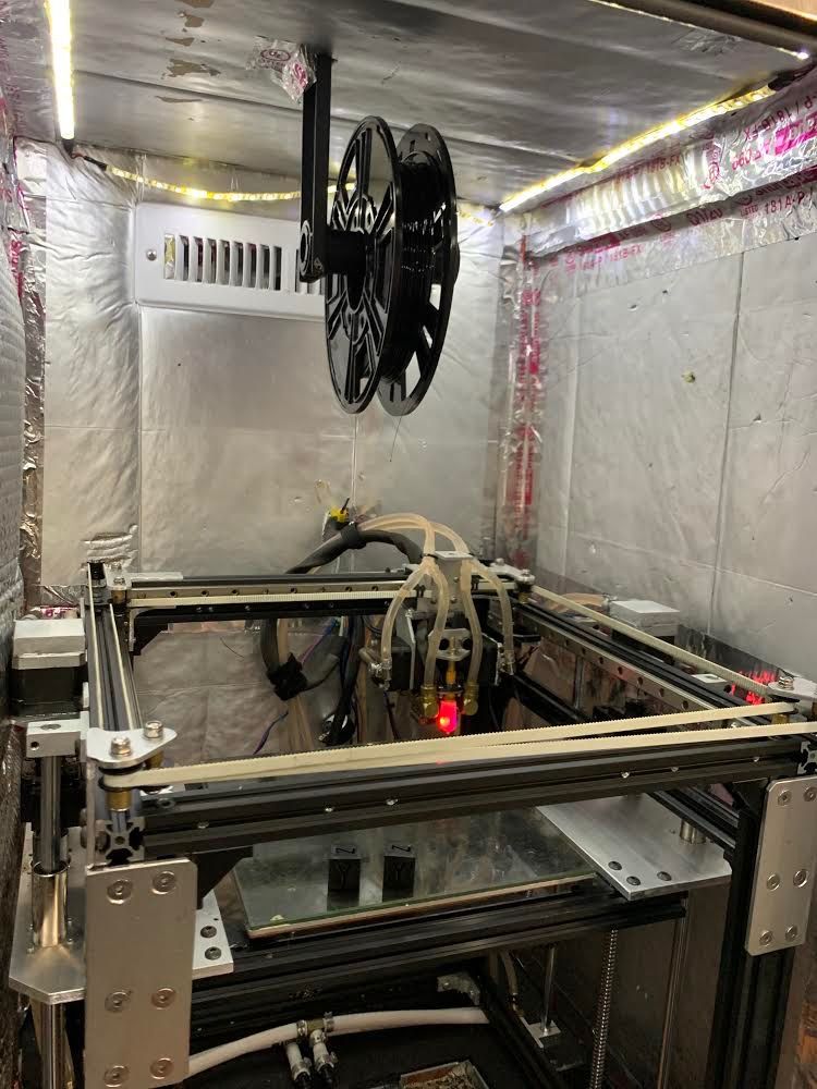
@luke-slaboratory The previous values where nulled out commands above the experiment section. I fabricated all the bracing and bare aluminum components, plus the smaller pre-made 2020 braces. I feel like the frames pretty solid, I used bronze spacers and thrust washers on the pulleys and they seem pretty smooth. Are the jerk values reasonable? should I drop the accel 3500-ish? I posted some pictures, sorry its hard to get any other angles it being inside the enclosure.


-
RE: Ghosting/ringing issues with new custom built core xyposted in Tuning and tweaking
@phaedrux Thanks for the feedback I really appreciate it. I run the steel core belts because I'm usually printing at 100C or more so they seem to hold up better with the heat. Should I try halving the acell? I noticed before I went to work this morning my max speed was way too high I dropped that from 15000 to 7500 and that made a big difference, printed another cube and cut the ringing down substantially on the X axis. I also notice the bed wobbling a little so I took the springs out and switched to some solid silicone bed mounts.
-
Ghosting/ringing issues with new custom built core xyposted in Tuning and tweaking
I’ve been struggling to with ghosting/ringing for the last few days so I thought id reach out for some help. I’ve mostly been toying with the acceleration values, the current values are based off the max acceleration calculator I found on sub thread. My retraction settings in cura are set at the nozzle diameter of 0.4 which is what Slice recommends for this configuration. All the stepper drive motors are set at 70% of their max values. Ill post my config below with some pictures of a calibration cube which is hot off the glass and one from earlier today with the original acceleration values nulled in the config. The cubes are from polycarbonate. Any advice would be greatly appreciated, thanks
; Physical Drive connection
M569 P0 S0 												    	  		                        ; X Drive 0
M569 P1 S0												  		  		                        ; Y Drive 1
M569 P9 S0								                  		  		                ; Z1 Drive 8
M569 P8 S0 									              		  		                  ; Z2 Drive 9 "U"
M569 P3 S1									              		  		                  ; Ex Drive 3
M569 P4 S0										          		  		                    ; Ex Drive 4
M584 X0 Y1 Z8:9 U9 E3:4 P3                                   	  		; Driver 0=X motor, D1= Y motor, D8:9 = Z motors, D3:4 E motors
M671 X110.625:345.625 Y117.5:117.5 S2                     		  		; Leadscrews at left (connected to Z) and right (connected to E1) of X axis
M350 E16:16 I0                                           		  		; configure microstepping without interpolation
M350 X16 Y16 Z16:16 U16 I1	    	        		      	 	  		; configure 16x microstepping with interpolation
M92 X80.00 Y80.00 Z800.00:800.00 U800 E415.00:415.00              		; set steps per mm
;M566 X900.00 Y900.00 Z12.00:12.00 U12.0 E800.00:800.00            		; set maximum instantaneous speed changes (mm/min)
;M203 X12000.00 Y12000.00 Z1000.00:1000.0 U1000.0 E8000.00:8000.0  		; set maximum speeds (mm/min
;M201 X2000.00 Y2000.00 Z20.00:20.0 U20.0 E500.00:500.00           		; set accelerations (mm/s^2)

;----Experimental Settings----
M566 X600 Y600 Z30:30 U30 E3000:3000 									; Set maximum instantaneous speed changes (mm/min)
M203 X15000 Y15000 Z1500:1500 U1500 E6000:6000 							; Set maximum speeds (mm/min)
M201 X4358.98 Y4358.98 Z100:100 U100 E10000:10000						; Set accelerations (mm/s^2) x/y:3000
:-----------------------------
M906 X1400.00 Y1400.00 Z1400.00:1400.00 U1400.00 E800.00:800.00 I30		; motor currents: 70% max (mA) and motor idle factor in per cent
M84 S30                                                  		  		; Set idle timeout

; Axis Limits
M208 X-23 Y0 Z0 U0 S1                                     ; set axis minima
M208 X220 Y220 Z275 U275 S0                               ; set axis maxima

; Endstops
M574 X1 S1 P"xstop"                                       ; configure active-high endstop for low end on X via pin xstop
M574 Y1 S1 P"ystop"                                       ; configure active-high endstop for low end on Y via pin ystop
M574 Z1 S2                                                ; configure Z-probe endstop for low end on Z

; Z-Probe
M950 S0 C"duex.pwm5"                            		      ; create servo pin 0 for BLTouch
M558 P9 C"^zprobe.in" H5 F120 T6000             		      ; set Z probe type to bltouch and the dive height + speeds
G31 P500 X0 Y0 Z1.016                         		      ; set Z probe trigger value. Prev Value: 1.283
M557 X20:200 Y0:130 S20                         		      ; define mesh grid

;Bed Heater
M308 S0 P"bedtemp" Y"thermistor" T100000 B3950     		  ; configure sensor 0 as thermistor on pin bedtemp
M950 H0 C"bedheat" T0                              		  ; create bed heater output on bedheat and map it to sensor 0
M307 H0 B1 S70.00                                  		  ; enable bang-bang mode for the bed heater and set PWM limit
M140 H0                                            		  ; map heated bed to heater 0
M143 H0 S199                                       		  ; set temperature limit for heater 0 to 199C

;Tool 0 Heater
M308 S2 P"duex.e2temp" Y"pt1000" R4700             		  ; configure sensor 2 as PT1000 on pin duex.e2temp
M950 H2 C"duex.e2heat" T2                          		  ; create nozzle heater output on duex.e2heat and map it to sensor 2
M307 H2 B0 S1.00                                   		  ; disable bang-bang mode for heater  and set PWM limit
M143 H2 S500                                       		  ; set temperature limit for heater 2 to 500C

;Tool 1 Heater
M308 S1 P"duex.e3temp" Y"pt1000" R4700             		  ; configure sensor 1 as PT1000 on pin duex.e3temp
M950 H1 C"duex.e3heat" T1                          		  ; create nozzle heater output on duex.e3heat and map it to sensor 1
M307 H1 B0 S1.00                                   		  ; disable bang-bang mode for heater  and set PWM limit
M143 H1 S500                                       		  ; set temperature limit for heater 1 to 500C

;Chamber Heater
M308 S3 P"duex.e4temp" Y"thermistor" T100000 B3950 		  ; configure sensor 3 as thermistor on pin duex.e4temp
M950 H3 C"duex.e4heat" T3                          		  ; create chamber heater output on duex.e4heat and map it to sensor 3
M307 H3 A11 C99000 D2000 B1                        		  ; chamber heater operates in bang-bang mode
;M307 H3 B1 S1.00                                  		  ; enable bang-bang mode for the chamber heater and set PWM limit
M141 H3                                            		  ; map chamber to heater 3
M143 H3 S150                                       		  ; set temperature limit for heater 3 to 150C

;Circulator Pump (24v)
M950 F0 C"fan1" Q500                                      ; create fan 0 on pin fan1 and set its frequency
M106 P0 S.9 L.6 X.8 H1:2:3 T45 C"Circulator Pump"         ; set fan 0 value. Thermostatic control is turned off

;Radiator fans (3:120mm @ 12v)
M950 F1 C"duex.fan3" Q500                      			  ; create fan 1 on pin duex.fan3 and set its frequency
M106 P1 S1 L.3 X1 H1:2:3 T45 C"Radiator fans"             ; set fan 1 value. Thermostatic control is turned off
M950 F1 C"duex.fan4" Q500                      			  ; create fan 2 on pin duex.fan4 and set its frequency
M106 P1 S1 L.3 X1 H1:2:3 T45 C"Radiator fans"             ; set fan 1 value. Thermostatic control is turned off
M950 F1 C"duex.fan5" Q500                      			  ; create fan 3 on pin duex.fan5 and set its frequency
M106 P1 S1 L.3 X1 H1:2:3 T45 C"Radiator fans"             ; set fan 1 value. Thermostatic control is turned off

; Tool 1
M563 P0 S"Extruder 1" D1 H2 F0f:1                     	  ; define tool 1
G10 P0 X0 Y0 Z0                                    		  ; set tool 1 axis offsets
G10 P0 R250 S0                                     		  ; set initial tool 1 active and standby temperatures to 250C

; Tool 0
M563 P1 S"Extruder 2" D0 H1 F0:1                     	  ; define tool 0
G10 P1 X15 Y0 Z0                                   		  ; set tool 0 axis offsets
G10 P1 R250 S0                                     		  ; set initial tool 0 active and standby temperatures to 250C


; Miscellaneous
M911 S12 R20 P"M913 X0 Y0 G91 M83 G1 Z3 E-5 F1000"        ; set voltage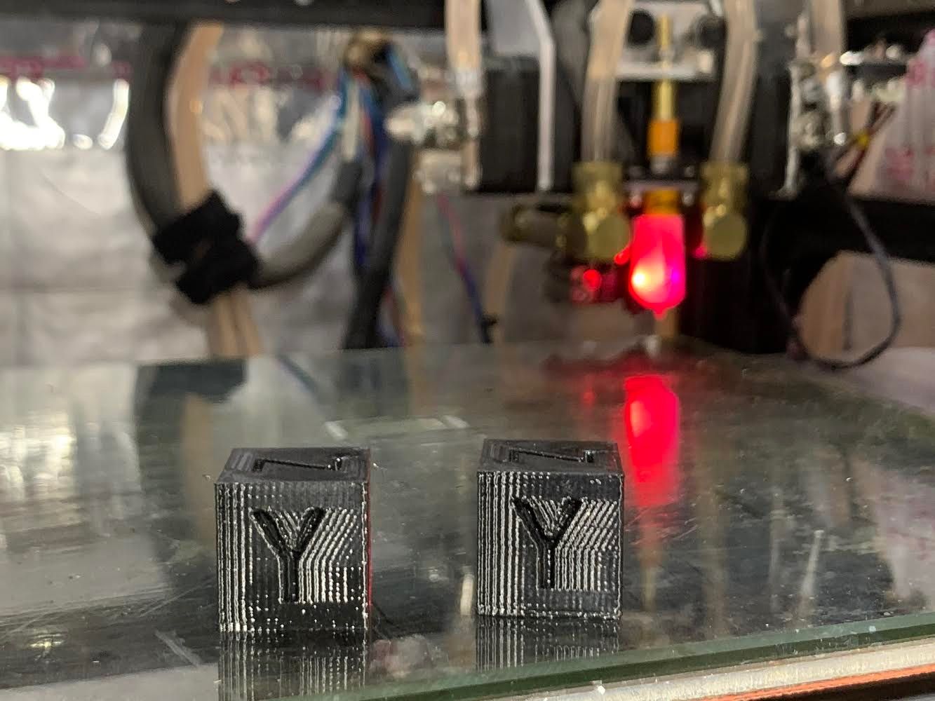
-
Replacement BL touch pins? [High heat printing fails]posted in General Discussion
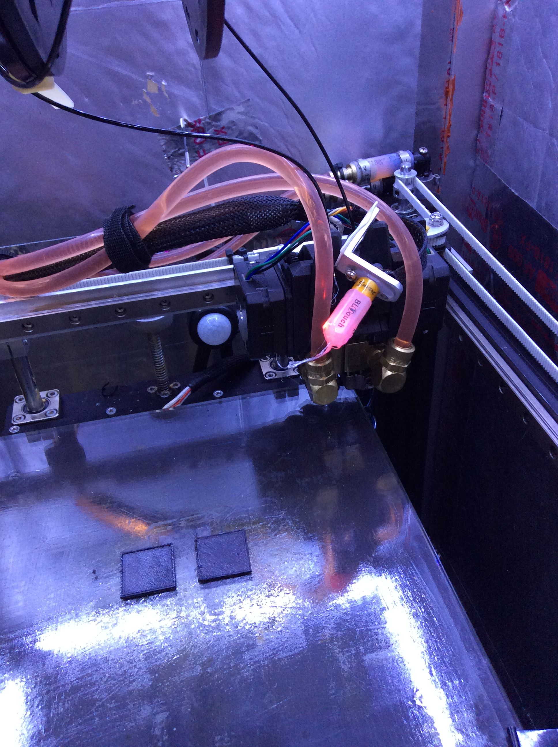
Just testing out my new dual extruder setup started printing some test squares with PC, chamber temp was up to 100C, everything was working extremely well, left the garage for 2 minutes and came back to this lol. If your wondering why my bl touch is two sided taped to the extruder body it’s because I designed a mount based of bondtechs cad model instead of measuring the actual extruder body. I printed the mount last night everything came out perfect other than it doesn’t fit was hoping the tape would of held out a little longer, back to the drawing board!

-
RE: Lead screw nut - brass vs POM and radial clearance/backlashposted in 3D Printing General Chat
You might want to look into 1204 ball screws, that's what's drives cnc machines. Their way more efficient / servicable than any lead screw brass bronze or pom nut. You can get them on amazon or eBay for around 40-50$ a piece
-
RE: High Temperature printingposted in General Discussion
High heat printer builds are like putting out small fires everywhere. As soon as you get a handle on something, something else comes into play. EVERYTHING starts to matter when you start building up that kind of heat. I just tested out my high heat version 3.0 today which went surprisingly well.
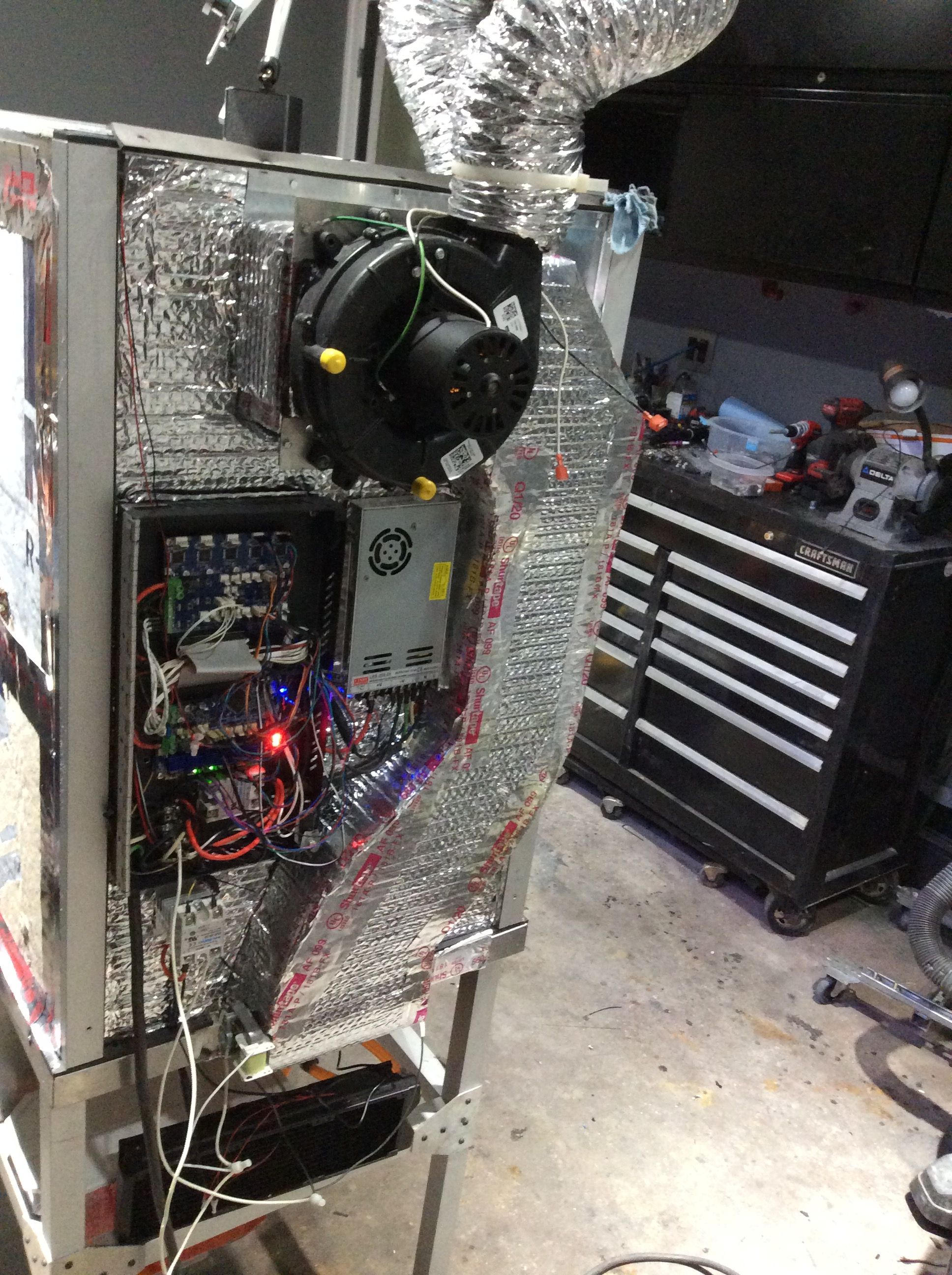
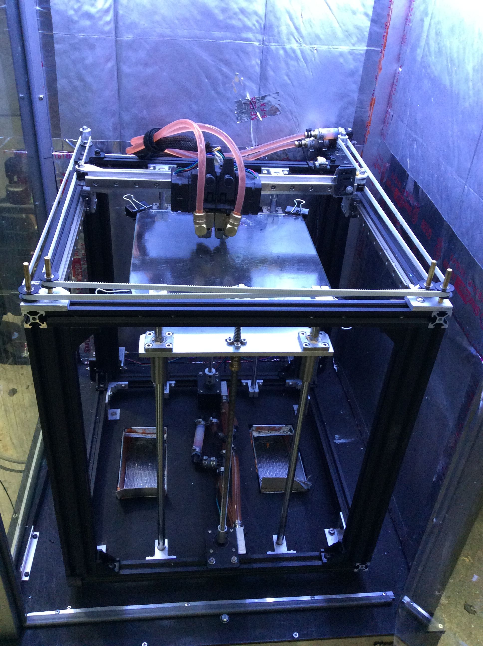
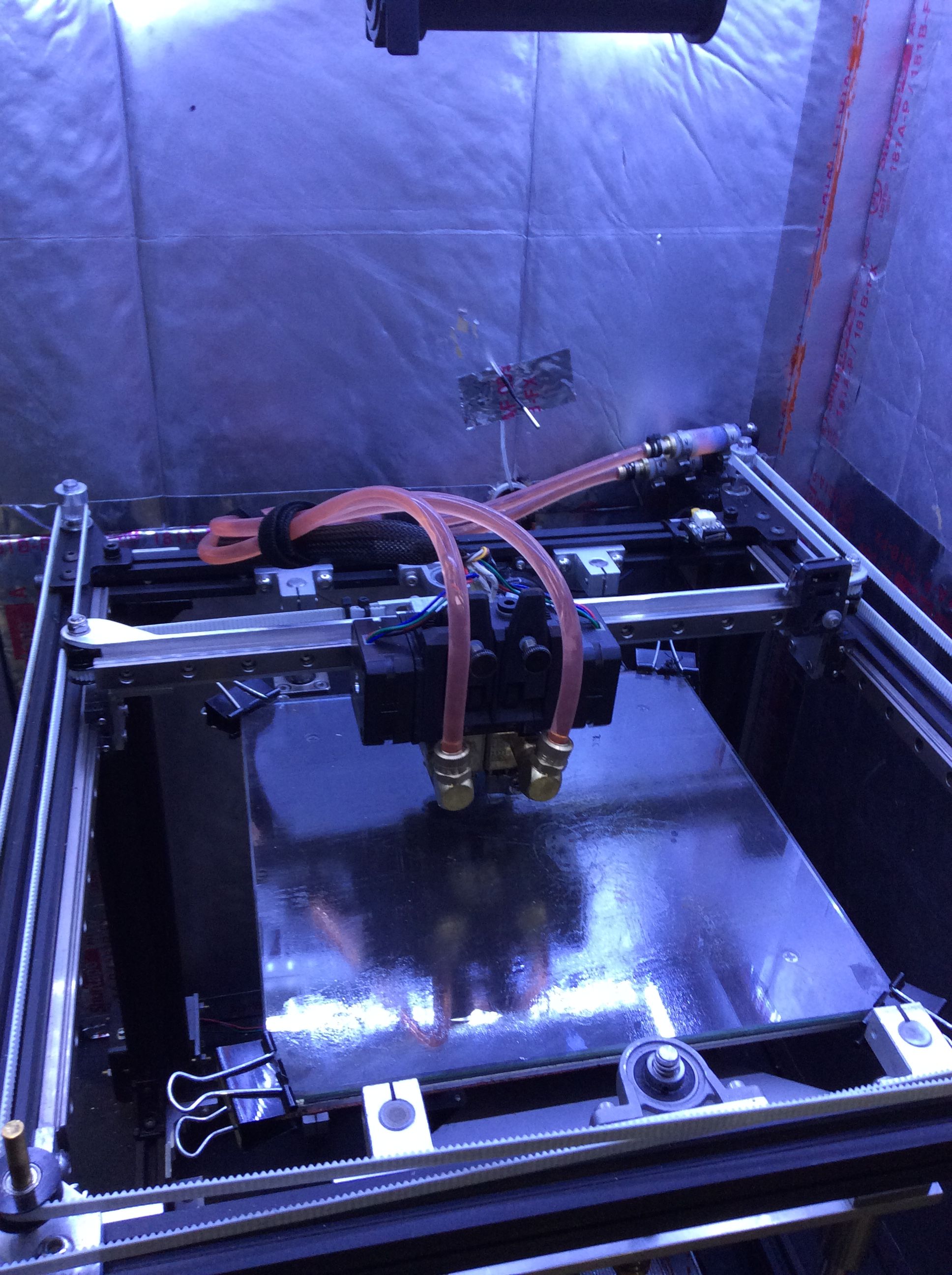 This is my work in progress, I built the enclosure out of aluminum on top of a old stainless toolbox my father-in-law gave me, the enclosure's 24 x 24 x 36. It has a 1400W heater/fan combo I found on amazon for $30 originally for a gas fireplace. Everything's insulated and sealed with fire-foam or high heat silicone. The setup utilizes a main return duct at the top of the enclosure used to recirculate the air, it maxes out at roughly 120C. Insides a Ender 5 that I Frankensteined into a core xy running a BMGX2-M w/ mosquito liquids, you can almost cook an egg on the extruder steppers...Its been a fun project but I feel like I got more wrapped up into the challenge of getting it there than anything. Any questions feel free to reach out.
 -
RE: High temp thermistor suggestionsposted in General Discussion
@bearer I ended up getting a pair on eBay for 16$ a piece, which look near identical to the slice pt1000 for 50.00 a piece. Differently dont have a print Fram just a small machine in a heated chamber.
-
RE: High temp thermistor suggestionsposted in General Discussion
@mendenmh thanks so much for your input sounds like pt1000's it is. Do you have any preferred sources otherwise I'll roll the dice on amazon.
-
RE: High temp thermistor suggestionsposted in General Discussion
Aren't the PT1000's plug-n-play with the duet 2 or would I need the daughterboard?
-
High temp thermistor suggestionsposted in General Discussion
I just upgraded My single bmg/ mosquito magnum to a BMG x-2 M and a pair of mosquito liquids (converted the mag to liq + 1). During the retro fitting process the slice engineering high temp thermistor must of gotten damaged. So now I’m faced with either making the order of 100$ for 2 thermistors...or look for a cheaper alternative to this problem. I mostly print high temp plastics ( Nylon, PC, and the occasional peek pek samples) so the thermistors need to be capable of temps well over 300C. This upgrades been nothing but a snowball of other upgrades to get everything to work properly so any suggestions to help stop the financial bleeding would be greatly appreciated.
-
RE: Thermistor help on new duex5 upgrade.posted in Duet Hardware and wiring
Solved, put an end on a old thermistor and its registering temp on the Duex board, time to tear it all back apart again! ::facetious::YAY!