@jay_s_uk well, i tinkered avery coordinates based fril tge POV of the nozzle, and now, everythink works flowlessly, thanks a lot 
last question :
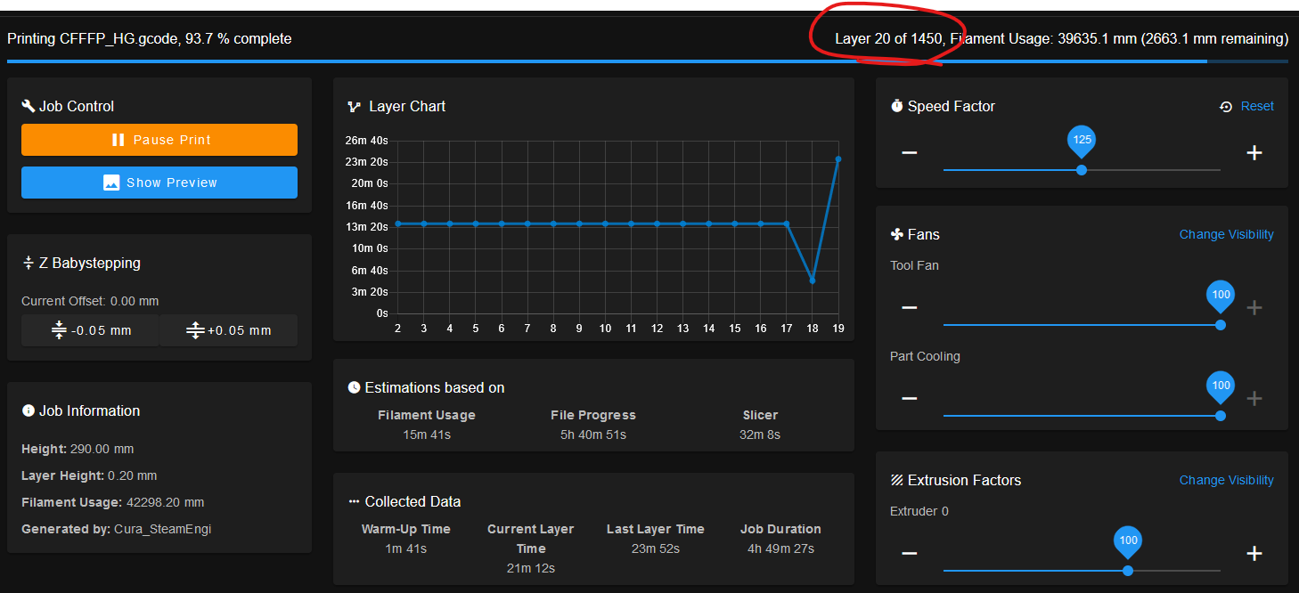
Do you know why my Duet display 1450 layers instead of the 30 of my print ?
@jay_s_uk well, i tinkered avery coordinates based fril tge POV of the nozzle, and now, everythink works flowlessly, thanks a lot 
last question :

Do you know why my Duet display 1450 layers instead of the 30 of my print ?
thanks to all of you, you just made my day.
and specially for the "You should probably update your firmware..." from @mrehorstdmd
I was already on 3.2.2 firmware version but in the RepRapFirmware Configuration Tool i have selected 1.21 ... what a noob mistake ^^
@alankilian yes, when i saw your endstop definition, i realisez they were something wrong with mine.
@Phaedrux I have already did this trick but thanks for the tips anyway.
@fcwilt Hi, i don't know where you see me talking about this piece of code :
M574 X2 S1 P"xstop"                                     ; configure active-high endstop for high end on X via pin xstop

M574 Y2 S1 P"ystop"                                     ; configure active-high endstop for high end on Y via pin ystop

M574 Z2 S1 P"zstop"
But now it works ! Thanks all of you.
Hey !
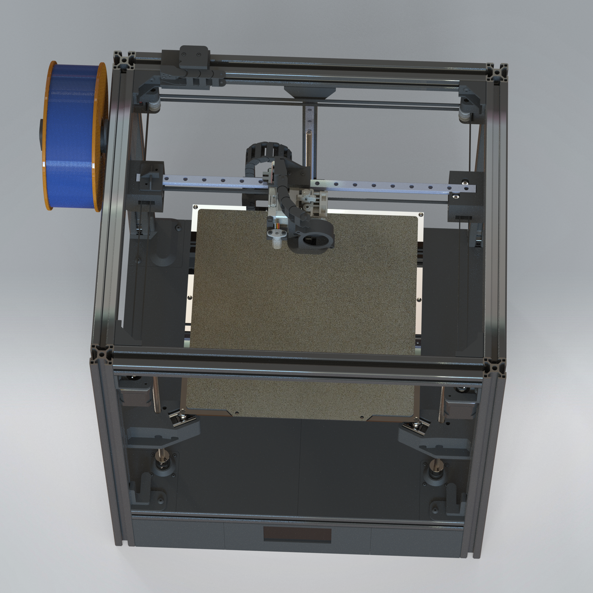
I build my printer from my own CAD, here are some pictures :
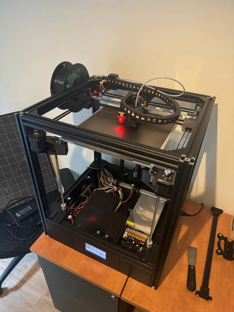
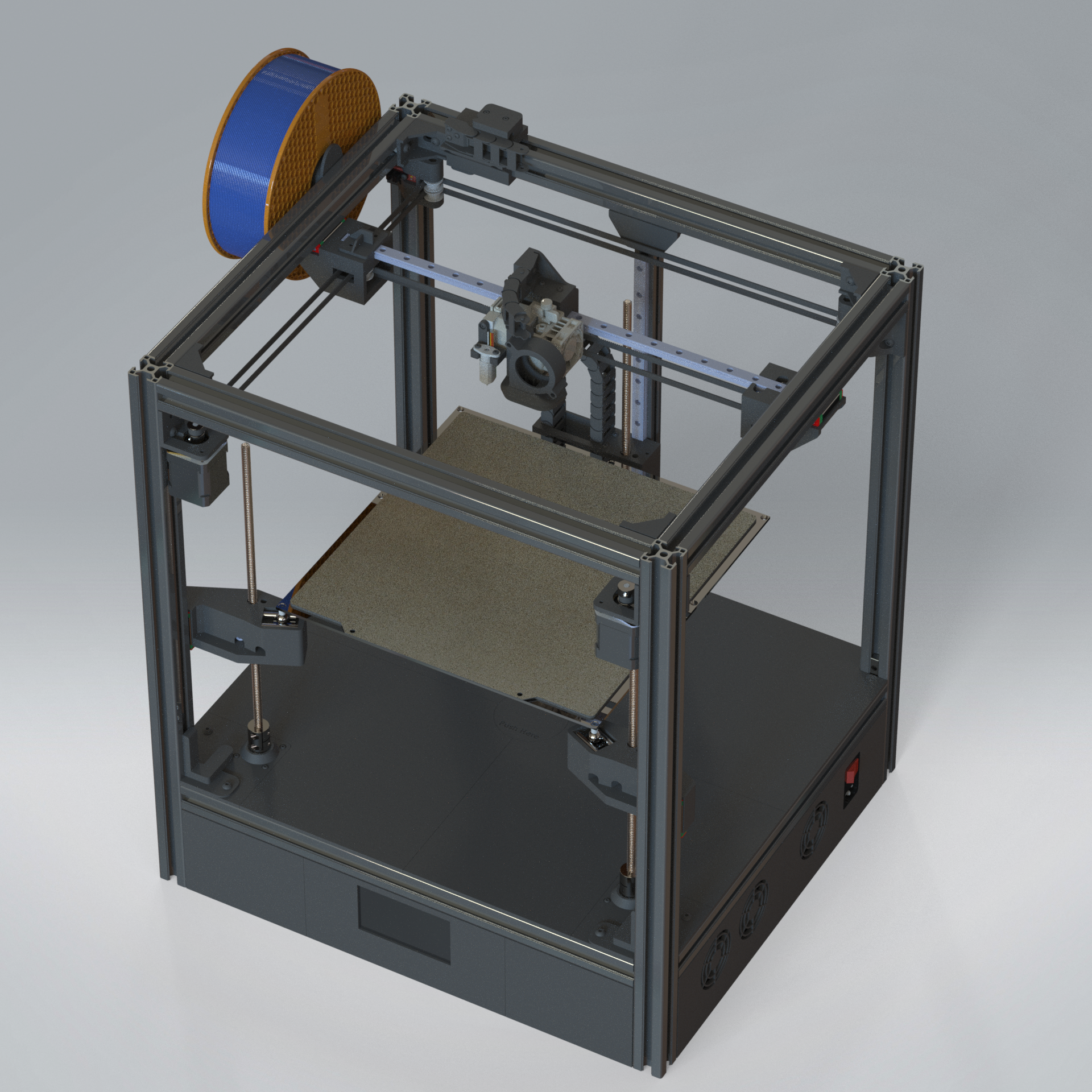
My issue is with my BL Touch and its positioning.
Here is a top View of the cordinates :
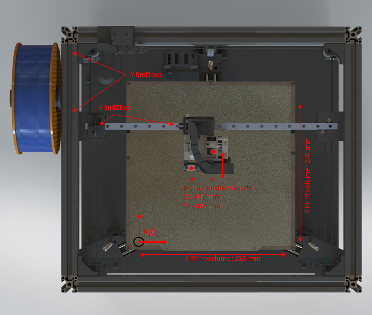
And here is my config.g :
; General preferences
M575 P1 S1 B57600                            ; enable support for PanelDue (Port IO_0)
G90                                          ; send absolute coordinates...
M83                                          ; ...but relative extruder moves
M550 P"HyberCube"                            ; set printer name
M669 K1                                      ; select CoreXY mode

; Network
;M551 P"MDP"                                 ; set password
M552 S1                                      ; enable network
M586 P0 S1                                   ; enable HTTP
M586 P1 S0                                   ; disable FTP
M586 P2 S0                                   ; disable Telnet

; Drives
M569 P0.0 S1                                 ; physical drive 0.0 goes forwards (X/Y Left)
M569 P0.1 S1                                 ; physical drive 0.1 goes forwards (X/Y Right)
M569 P0.3 S1	      						 ; physical drive 0.2 goes forwards (Extruder)
M569 P0.4 S1 D3                              ; physical drive 0.4 goes forwards (Z1 - Front Right)
M569 P0.5 S1 D3                              ; physical drive 0.4 goes forwards (Z2 - Front Left)
M569 P0.6 S1 D3                              ; physical drive 0.4 goes forwards (Z3 - Back)

M584 X0.0 Y0.1 Z0.4:0.5:0.6 E0.3             ; set drive mapping
M350 X16 Y16 Z16 E16 I1                      ; configure microstepping with interpolation
M92 X80.00 Y80.00 Z400.00 E336.00            ; set steps per mm
M566 X600.00 Y600.00 Z120.00 E200.00         ; set maximum instantaneous speed changes (mm/min)
M203 X40000.00 Y40000.00 Z3000.00 E350.00    ; set maximum speeds (mm/min)
M201 X4000.00 Y4000.00 Z150.00 E500.00       ; set accelerations (mm/s^2)
M906 X1000 Y1000 Z1200 E800 I60              ; set motor peak currents (mA) and motor idle factor in per cent (Peak Current = RMS Current x 1.414.)
M84 S30                                      ; Set idle timeout

; Axis Limits
M208 X0 Y0 Z0 S1                             ; set axis minima
M208 X285 Y270 Z290 S0                       ; set axis maxima
;M208 X290 Y275 Z290 S0                      ; Dimention maxi maxi (hors du lit chauffant)

; Endstops
M574 X1 S1 P"io1.in"                         ; configure switch-type (e.g. microswitch) endstop
M574 Y2 S1 P"io2.in"                         ; configure switch-type (e.g. microswitch) endstop

; Z-Probe
M950 S0 C"io3.out"							 ; Create a GPIO/Servo pin index
M558 P9 C"io3.in" H5 F2000:120 T6000         ; set Z probe type to switch and the dive height + speeds

;--------------------------------// Paramétrage Hauteur BLTouch - Buse \\--------------------------

G31 P500 X-41.5 Y-30.5 Z1.20                  ; set Z probe trigger value, offset and trigger height

;Utiliser la Macro "Réglage BL Touch" La valeur de Z qui convient doit être soustraite au Z de la commande ci dessus
;Exemple : Z = -1 pour que le plateau soit ok, Z de G31 = 0 --> 0 - -1 = 1
;Une plus grande valeur de Z = La buse sera plus proche du plateau

;---------------------------------------------------------------------------------------------------

M671 X294:-28:137 Y-8:-8:315 S10			 ; position of bed pivot point at front right, front left and rear middle (Same order as defined in the M584 Command)
M557 X0:285 Y0:270 P5:5						 ; Define probe meshing + number of probing point

; Heaters
M308 S0 P"temp0" Y"thermistor" T100000 B4138 ; configure sensor 0 as thermistor on pin temp0
M950 H0 C"out0" T0                           ; create bed heater output on out0 and map it to sensor 0
M307 H0 R0.232 K0.223:0.000 D1.76 E1.35 S1.00 B0		;PID BED
M140 H0                                      ; map heated bed to heater 0
M143 H0 S100                                 ; set temperature limit for heater 0 to 120C

M308 S1 P"temp1" Y"thermistor" T100000 B4138 ; configure sensor 1 as thermistor on pin temp1
M950 H1 C"out1" T1                           ; create nozzle heater output on out1 and map it to sensor 1
M307 H1 R2.148 K0.597:0.000 D6.12 E1.35 S1.00 B0 V23.9  ;PID NOZZLE
M143 H1 S280                                 ; set temperature limit for heater 1 to 280C

; Fans
M950 F1 C"out4" Q65535
M106 P1 L1 X1 T170 H1:1 C"HotEnd"

M950 F0 C"out5" Q500
M106 P0 L1 X1 H-1 C"Part Cooling"

M950 F2 C"out6" Q65535
M106 P2 T170 H1:1 C"Electronics"

; Tools
M563 P0 S"Print Head" D0 H1 F0               ; define tool 0
M568 P0 R0 S0 A0                             ; set initial tool 0 active and standby temperatures
M572 D0 S0.025								 ; Set pressure advance
T0
my problem is that when I probe the printing plate with my BL Touch (my bed is drived by three independent motors, for automatic correction) I don't know what coordinates I should enter.
my "bed.g" is as follow :
; bed.g
; called to perform automatic bed compensation via G32

;Début G28
G91                   	; relative positioning
G1 H2 Z5 F6000       	; lift Z relative to current position
G1 H1 X-305 Y+305 F6000 ; move quickly to X or Y endstop and stop there (first pass)
G1 H1 X-305             ; home X axis
G1 H1 Y+305             ; home Y axis
G1 X5 Y-5 F6000   	    ; go back a few mm
G1 H1 X-305 F360        ; move slowly to X axis endstop once more (second pass)
G1 H1 Y+305 F360        ; move slowly to Y axis endstop once more (second pass)
G90             	    ; absolute positioning
G1 X184 Y168 F6000   	; go to first probe point (Cordonnées = Centre du plateau du point de vue du BL Touch)
G91                   	; relative positioning
G30 F1200               ; home Z by probing the bed
G90             		; absolute positioning
;Fin G28

G30 P0 X51.5 Y40.5 Z-99999  	; probe near a leadscrew
G30 P1 X316.5 Y40.5 Z-99999  	; probe near a leadscrew
G30 P2 X184 Y290.5 Z-99999 S3  ; probe near a leadscrew and calibrate 3 motors

G1 X150 Y150 Z120 F6000 		; go to first probe point
But i don't know the cordinates to enter in the last three "G30".
I would like to probe 3 point, one neer each leadscrew (X10 ; Y10 / X275 ; Y10 / X142.5 Y260)
Should i enter the coordinates at X10 ; Y10 from the point of view of the nozzle or BL TOUCH ?
I tried many things but it very often ended up with my head crashing in the gantry ^^
Thanks
@jay_s_uk well, i tinkered avery coordinates based fril tge POV of the nozzle, and now, everythink works flowlessly, thanks a lot 
last question :

Do you know why my Duet display 1450 layers instead of the 30 of my print ?
Hey !
I build my printer from my own CAD, here are some pictures :


My issue is with my BL Touch and its positioning.
Here is a top View of the cordinates :

And here is my config.g :
; General preferences
M575 P1 S1 B57600                            ; enable support for PanelDue (Port IO_0)
G90                                          ; send absolute coordinates...
M83                                          ; ...but relative extruder moves
M550 P"HyberCube"                            ; set printer name
M669 K1                                      ; select CoreXY mode

; Network
;M551 P"MDP"                                 ; set password
M552 S1                                      ; enable network
M586 P0 S1                                   ; enable HTTP
M586 P1 S0                                   ; disable FTP
M586 P2 S0                                   ; disable Telnet

; Drives
M569 P0.0 S1                                 ; physical drive 0.0 goes forwards (X/Y Left)
M569 P0.1 S1                                 ; physical drive 0.1 goes forwards (X/Y Right)
M569 P0.3 S1	      						 ; physical drive 0.2 goes forwards (Extruder)
M569 P0.4 S1 D3                              ; physical drive 0.4 goes forwards (Z1 - Front Right)
M569 P0.5 S1 D3                              ; physical drive 0.4 goes forwards (Z2 - Front Left)
M569 P0.6 S1 D3                              ; physical drive 0.4 goes forwards (Z3 - Back)

M584 X0.0 Y0.1 Z0.4:0.5:0.6 E0.3             ; set drive mapping
M350 X16 Y16 Z16 E16 I1                      ; configure microstepping with interpolation
M92 X80.00 Y80.00 Z400.00 E336.00            ; set steps per mm
M566 X600.00 Y600.00 Z120.00 E200.00         ; set maximum instantaneous speed changes (mm/min)
M203 X40000.00 Y40000.00 Z3000.00 E350.00    ; set maximum speeds (mm/min)
M201 X4000.00 Y4000.00 Z150.00 E500.00       ; set accelerations (mm/s^2)
M906 X1000 Y1000 Z1200 E800 I60              ; set motor peak currents (mA) and motor idle factor in per cent (Peak Current = RMS Current x 1.414.)
M84 S30                                      ; Set idle timeout

; Axis Limits
M208 X0 Y0 Z0 S1                             ; set axis minima
M208 X285 Y270 Z290 S0                       ; set axis maxima
;M208 X290 Y275 Z290 S0                      ; Dimention maxi maxi (hors du lit chauffant)

; Endstops
M574 X1 S1 P"io1.in"                         ; configure switch-type (e.g. microswitch) endstop
M574 Y2 S1 P"io2.in"                         ; configure switch-type (e.g. microswitch) endstop

; Z-Probe
M950 S0 C"io3.out"							 ; Create a GPIO/Servo pin index
M558 P9 C"io3.in" H5 F2000:120 T6000         ; set Z probe type to switch and the dive height + speeds

;--------------------------------// Paramétrage Hauteur BLTouch - Buse \\--------------------------

G31 P500 X-41.5 Y-30.5 Z1.20                  ; set Z probe trigger value, offset and trigger height

;Utiliser la Macro "Réglage BL Touch" La valeur de Z qui convient doit être soustraite au Z de la commande ci dessus
;Exemple : Z = -1 pour que le plateau soit ok, Z de G31 = 0 --> 0 - -1 = 1
;Une plus grande valeur de Z = La buse sera plus proche du plateau

;---------------------------------------------------------------------------------------------------

M671 X294:-28:137 Y-8:-8:315 S10			 ; position of bed pivot point at front right, front left and rear middle (Same order as defined in the M584 Command)
M557 X0:285 Y0:270 P5:5						 ; Define probe meshing + number of probing point

; Heaters
M308 S0 P"temp0" Y"thermistor" T100000 B4138 ; configure sensor 0 as thermistor on pin temp0
M950 H0 C"out0" T0                           ; create bed heater output on out0 and map it to sensor 0
M307 H0 R0.232 K0.223:0.000 D1.76 E1.35 S1.00 B0		;PID BED
M140 H0                                      ; map heated bed to heater 0
M143 H0 S100                                 ; set temperature limit for heater 0 to 120C

M308 S1 P"temp1" Y"thermistor" T100000 B4138 ; configure sensor 1 as thermistor on pin temp1
M950 H1 C"out1" T1                           ; create nozzle heater output on out1 and map it to sensor 1
M307 H1 R2.148 K0.597:0.000 D6.12 E1.35 S1.00 B0 V23.9  ;PID NOZZLE
M143 H1 S280                                 ; set temperature limit for heater 1 to 280C

; Fans
M950 F1 C"out4" Q65535
M106 P1 L1 X1 T170 H1:1 C"HotEnd"

M950 F0 C"out5" Q500
M106 P0 L1 X1 H-1 C"Part Cooling"

M950 F2 C"out6" Q65535
M106 P2 T170 H1:1 C"Electronics"

; Tools
M563 P0 S"Print Head" D0 H1 F0               ; define tool 0
M568 P0 R0 S0 A0                             ; set initial tool 0 active and standby temperatures
M572 D0 S0.025								 ; Set pressure advance
T0
my problem is that when I probe the printing plate with my BL Touch (my bed is drived by three independent motors, for automatic correction) I don't know what coordinates I should enter.
my "bed.g" is as follow :
; bed.g
; called to perform automatic bed compensation via G32

;Début G28
G91                   	; relative positioning
G1 H2 Z5 F6000       	; lift Z relative to current position
G1 H1 X-305 Y+305 F6000 ; move quickly to X or Y endstop and stop there (first pass)
G1 H1 X-305             ; home X axis
G1 H1 Y+305             ; home Y axis
G1 X5 Y-5 F6000   	    ; go back a few mm
G1 H1 X-305 F360        ; move slowly to X axis endstop once more (second pass)
G1 H1 Y+305 F360        ; move slowly to Y axis endstop once more (second pass)
G90             	    ; absolute positioning
G1 X184 Y168 F6000   	; go to first probe point (Cordonnées = Centre du plateau du point de vue du BL Touch)
G91                   	; relative positioning
G30 F1200               ; home Z by probing the bed
G90             		; absolute positioning
;Fin G28

G30 P0 X51.5 Y40.5 Z-99999  	; probe near a leadscrew
G30 P1 X316.5 Y40.5 Z-99999  	; probe near a leadscrew
G30 P2 X184 Y290.5 Z-99999 S3  ; probe near a leadscrew and calibrate 3 motors

G1 X150 Y150 Z120 F6000 		; go to first probe point
But i don't know the cordinates to enter in the last three "G30".
I would like to probe 3 point, one neer each leadscrew (X10 ; Y10 / X275 ; Y10 / X142.5 Y260)
Should i enter the coordinates at X10 ; Y10 from the point of view of the nozzle or BL TOUCH ?
I tried many things but it very often ended up with my head crashing in the gantry ^^
Thanks
thanks to all of you, you just made my day.
and specially for the "You should probably update your firmware..." from @mrehorstdmd
I was already on 3.2.2 firmware version but in the RepRapFirmware Configuration Tool i have selected 1.21 ... what a noob mistake ^^
@alankilian yes, when i saw your endstop definition, i realisez they were something wrong with mine.
@Phaedrux I have already did this trick but thanks for the tips anyway.
@fcwilt Hi, i don't know where you see me talking about this piece of code :
M574 X2 S1 P"xstop"                                     ; configure active-high endstop for high end on X via pin xstop

M574 Y2 S1 P"ystop"                                     ; configure active-high endstop for high end on Y via pin ystop

M574 Z2 S1 P"zstop"
But now it works ! Thanks all of you.
I'm struggling with the detection of my optical endstop on my duet 2 Wifi.
EndStop used : https://www.aliexpress.com/item/32861519345.html?spm=a2g0s.9042311.0.0.27426c378PGuhp
I have wired 3 of them this way (on x, y and z) :
V -> 3.3v
S -> Signal
G -> Ground
There is only those 3 optical sensor connected to the board.
With power, the optical switch are correctly powered and the red led on top is On
(this LED)

And the LED on the Duet board are also On (and very bright) and when i toggle the switch, both LED on the switch and the Duet turn off.

But when i try to send M119 (with the sensor triggered or not) i get :
Endstops - X: no endstop, Y: no endstop, Z: no endstop, Z probe: at min stop
What i tryed :
Solder a 220Ohm resistor to the R1 Resistor of my switch to get a 100 Ohm average resistor. -> no difference, the LEDs have the same behaviour and same for M119.
Changing M574 from S1 to S0
Connect the sensor differently :
V -> 5v
S -> Signal
G -> Ground
5V taken here :

No difference, the LEDs still works like a charm but nothing more with the M119 command.
I don't think the issues come from the sensor or the duet board but rather on the firmware side because of the LED working normally.
Here is my my config.g :
; Configuration file for Duet WiFi (firmware version 1.21)
; executed by the firmware on start-up
;
; generated by RepRapFirmware Configuration Tool v3.2.3 on Thu Mar 04 2021 23:01:24 GMT+0100

; General preferences
G90                                     ; send absolute coordinates...
M83                                     ; ...but relative extruder moves
M550 P"HyberCube"                       ; set printer name
M667 S1                                 ; select CoreXY mode

; Network
M551 P"Nice try :)"                     ; set password
M552 S1                                 ; enable network
M586 P0 S1                              ; enable HTTP
M586 P1 S0                              ; disable FTP
M586 P2 S0                              ; disable Telnet

; Drives
M569 P0 S1                              ; physical drive 0 goes forwards
M569 P1 S1                              ; physical drive 1 goes forwards
M569 P2 S1                              ; physical drive 2 goes forwards
M569 P3 S1                              ; physical drive 3 goes forwards
M584 X0 Y1 Z2 E3                        ; set drive mapping
M350 X16 Y16 Z16 E16 I1                 ; configure microstepping with interpolation
M92 X80.00 Y80.00 Z400.00 E420.00       ; set steps per mm
M566 X900.00 Y900.00 Z60.00 E120.00     ; set maximum instantaneous speed changes (mm/min)
M203 X6000.00 Y6000.00 Z180.00 E1200.00 ; set maximum speeds (mm/min)
M201 X500.00 Y500.00 Z20.00 E250.00     ; set accelerations (mm/s^2)
M906 X800 Y800 Z800 E800 I30            ; set motor currents (mA) and motor idle factor in per cent
M84 S30                                 ; Set idle timeout

; Axis Limits
M208 X0 Y0 Z0 S1                        ; set axis minima
M208 X300 Y300 Z300 S0                  ; set axis maxima

; Endstops
M574 X1 Y1 Z1 S1                        ; set active high endstops

; Z-Probe
M558 P5 H5 F120 T6000                   ; set Z probe type to switch and the dive height + speeds
G31 P500 X0 Y0 Z0                       ; set Z probe trigger value, offset and trigger height
M557 X15:215 Y15:195 S20                ; define mesh grid

; Heaters
M305 P0 T100000 B4138 R4700             ; set thermistor + ADC parameters for heater 0
M143 H0 S120                            ; set temperature limit for heater 0 to 120C
M305 P1 T100000 B4138 R4700             ; set thermistor + ADC parameters for heater 1
M143 H1 S280                            ; set temperature limit for heater 1 to 280C

; Fans
M106 P0 S0 I0 F500 H-1                  ; set fan 0 value, PWM signal inversion and frequency. Thermostatic control is turned off
M106 P1 S1 I0 F500 H1 T45               ; set fan 1 value, PWM signal inversion and frequency. Thermostatic control is turned on

; Tools
M563 P0 D0 H1 F0                        ; define tool 0
G10 P0 X0 Y0 Z0                         ; set tool 0 axis offsets
G10 P0 R0 S0                            ; set initial tool 0 active and standby temperatures to 0C

; Custom settings are not defined

; Miscellaneous
M575 P1 S1 B57600                       ; enable support for PanelDue
Thanks a lot if your have ideas to solve this issue, i lost many hours on it...