@droftarts @phaedrux Thank you for your kind remarks to my ignorance.
I finished setting up the M671 today. The result on Bed.g looks like this.
Bed image: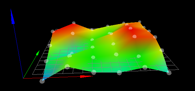
G32Results:G32
Manual corrections required: 0.00 turn up (0.00mm) 0.19 turn down (0.09mm) 0.13 turn down (0.07mm) 0.19 turn down (0.10mm)
Thank you for telling us.
I don't think I could have done so much with my knowledge.
Posts made by kotuo
-
RE: The height map is not created correctlyposted in IR Height Sensor
-
RE: The height map is not created correctlyposted in IR Height Sensor
@phaedrux Thank you for your reply.
I now understand the relationship between X and Y. Thank you. -
RE: The height map is not created correctlyposted in IR Height Sensor
@droftarts Thank you for your reply.
@droftarts said in The height map is not created correctly:
Is the probe in front or behind the nozzle? To the left or the right?
The nozzle is in front of the printer. And the probe is set at 20mm in front from the nozzle.
-
RE: The height map is not created correctlyposted in IR Height Sensor
@droftarts Thank you for your reply.
This picture is taken from the back of the printer.
Y is about -20 places from the maximum
X is about two thirds of the way from the minimum.
In the printer settings, this is the maximum position.
In order to improve the serviceability of the printer, the bed can be moved up to 500mm -
RE: The height map is not created correctlyposted in IR Height Sensor
@droftarts Sorry for the delay in replying.
Thank you for your reply.
I have reworked the parts you pointed out.I rewrote homeall.g and it looks like this.
; homeall.g
; called to home all axes
;
; generated by RepRapFirmware Configuration Tool v3.3.5 on Sun Nov 14 2021 09:23:55 GMT+0900 (日本標準時)
G91                     ; relative positioning
G1 H2 Z5 F6000          ; lift Z relative to current position
G1 H1 X-305 Y-305 F1800 ; move quickly to X and Y axis endstops and stop there (first pass)
G1 H2 X5 Y5 F6000       ; go back a few mm
G1 H1 X-305 Y-305 F360  ; move slowly to X and Y axis endstops once more (second pass)
G1 H1 Z-305 F360        ; move Z down stopping at the endstop
G90                     ; absolute positioning
G1 X150 Y150 Z5 F2000 ; put head over the centre of the bed, or wherever you want to probe
G30 ; lower head, stop when probe triggered and set Z to trigger height


;G92 Z0                  ; set Z position to axis minimum (you may want to adjust this)

; Uncomment the following lines to lift Z after probing
;G91                    ; relative positioning
;G1 Z5 F100             ; lift Z relative to current position
;G90                    ; absolute positioning
As a result, when HomeAll is done, after the X and Y axis hit the limit switch, the carriage moves to the centre and is now Z-probed.
The next question is about the probe offset.
This is a CAD simulation of my probe.
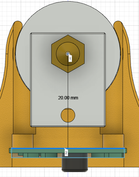
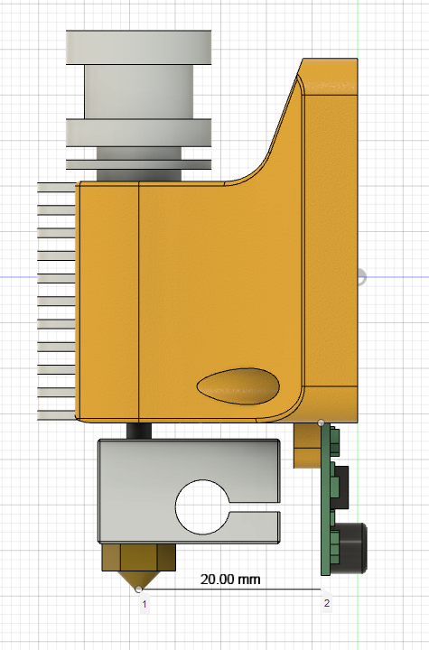
You will probably need to enter X+20 or X-20 as the offset for G31.
I have checked the offset and if I move the probe to where the hot end nozzle is marked, then at +20mm the probe will be in the same position as the nozzle.
I set it to X20 on the G31.
However, I don't think that the Y axis offset is moving from the nozzle to either side. In this case, is it correct to set the Y offset to 0?The next question is about Using the Manual Bed Levelling Assistant.
The prerequisite for Using the Manual Bed Levelling Assistant is
{You need to use the {M671 command to define the X and Y coordinates of the adjusting screw. The M671 command must be specified after the M667 or M669 command in config.g}.
but the adjustment screw on my printer bed is on the inside of the bed.
Is this something I should be concerned about?
Also, there is no M669 in my Config.g. What should I do in this case? -
RE: The height map is not created correctlyposted in IR Height Sensor
@phaedrux Thank you for your reply.
@phaedrux said in The height map is not created correctly:
Do you actually use bed.g? Or call it with G32 at any point?
I ran G32 and found that P1 and P4 were not probed as the probes were sticking out of the bed.
@phaedrux said in The height map is not created correctly:
homeall.gファイルとhomez.gファイルを投稿できますか?
This is Homeall
; homeall.g
; called to home all axes
;
; generated by RepRapFirmware Configuration Tool v3.3.5 on Sun Nov 14 2021 09:23:55 GMT+0900 (日本標準時)
G91                     ; relative positioning
G1 H2 Z5 F6000          ; lift Z relative to current position
G1 H1 X-305 Y-305 F1800 ; move quickly to X and Y axis endstops and stop there (first pass)
G1 H2 X5 Y5 F6000       ; go back a few mm
G1 H1 X-305 Y-305 F360  ; move slowly to X and Y axis endstops once more (second pass)
G1 H1 Z-305 F360        ; move Z down stopping at the endstop
G90                     ; absolute positioning
G92 Z0                  ; set Z position to axis minimum (you may want to adjust this)

; Uncomment the following lines to lift Z after probing
;G91                    ; relative positioning
;G1 Z5 F100             ; lift Z relative to current position
;G90                    ; absolute positioning
This is Homez
; homez.g
; called to home the Z axis
;
; generated by RepRapFirmware Configuration Tool v3.3.5 on Sun Nov 14 2021 09:23:56 GMT+0900 (日本標準時)
G91 ; relative mode
G1 S2 Z5 F200 ; raise head 4mm to ensure it is above the Z probe trigger height
G90 ; back to absolute mode
G1 X150 Y150 F2000 ; put head over the centre of the bed, or wherever you want to probe
G30 ; lower head, stop when probe triggered and set Z to trigger height

;G91               ; relative positioning
;G1 H2 Z5 F6000    ; lift Z relative to current position
;G1 H1 Z-305 F1800 ; move Z down until the endstop is triggered
;G92 Z0            ; set Z position to axis minimum (you may want to adjust this)

; Uncomment the following lines to lift Z after probing
;G91              ; relative positioning
;G1 Z5 F100       ; lift Z relative to current position
;G90              ; absolute positioning
@phaedrux said in The height map is not created correctly:
When the heightmap has such a large offset it's usually because the mesh has been created without the z axis being homed with the probe first.
Now I understand why the height map was made so low.
@phaedrux said in The height map is not created correctly:
Your homing files should home the Z axis with the probe using G30 at the center of the bed to set the Z0 location. Then create a fresh height map.
Does this mean that I need to do a paper filler test in the centre of the bet and then run 「G92 Z0」 and then 「G29」?
-
RE: The height map is not created correctlyposted in IR Height Sensor
@droftarts Thank you for your reply.
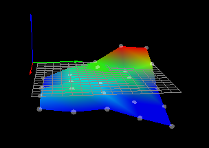
In my printer, the X axis is currently the axis that moves the bed.As @droftarts pointed out, there is a possibility that the large FAN attached to the hot end has a negative effect, so I removed the FAN and measured again.
Here is the resulting image.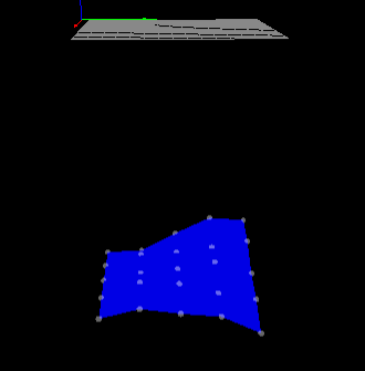
Here are the results after adjusting the height again.
-
RE: The height map is not created correctlyposted in IR Height Sensor
@phaedrux Thank you for your reply.
The shape is very similar to my Prusa printer, so it is a Cartesian type.
Photo:
The printer's bed is usually used with a black paper between a glass plate and an aluminium plate.
photo:
The sensor used is an IR probe.
Photo:
Here is the probe I bought
URL:IRSensor
Finally, here is the Bed.g file.; bed.g ; called to perform automatic bed compensation via G32 ; ; generated by RepRapFirmware Configuration Tool v3.3.5 on Sun Nov 14 2021 09:23:54 GMT+0900 (日本標準時) M561 ; clear any existing bed transform M401 ; deploy Z probe if necessary G30 P0 X60 Y30 Z-99999 ; define 4 points in a clockwise direction around the bed, starting near (0,0) G30 P1 X330 Y30 Z-99999 G30 P2 X330 Y290 Z-99999 G30 P3 X60 Y290 Z-99999 G30 P4 X150 Y150 Z-99999 S0 ; finally probe bed centre, and calculate compensation M402 ; retract the Z probe G1 X0 Y0 F5000 ; move the head to the corner (optional) ;M561 ; clear any existing bed transform ;M401 ; deploy Z probe if necessary ;G30 P0 X10 Y10 Z-99999 ; define 4 points in a clockwise direction around the bed, starting near (0,0) ;G30 P1 X10 Y190 Z-99999 ;G30 P2 X190 Y190 Z-99999 ;G30 P3 X190 Y10 Z-99999 ;G30 P4 X100 Y100 Z-99999 S0 ; finally probe bed centre, and calculate compensation ;M402 ; retract the Z probe ;G1 X0 Y0 F5000 ; move the head to the corner (optional) ;M561 ; clear any bed transform ;G29 ; probe the bed and enable compensation -
RE: The height map is not created correctlyposted in IR Height Sensor
@droftarts said in The height map is not created correctly:
config.g
Thank you for your patience.
Here is my config.g.; Configuration file for Duet WiFi (firmware version 3.3) ; executed by the firmware on start-up ; ; generated by RepRapFirmware Configuration Tool v3.3.5 on Fri Nov 05 2021 01:14:08 GMT+0900 (日本標準時) ; General preferences M575 P1 S1 B57600 ; enable support for PanelDue G90 ; send absolute coordinates... M83 ; ...but relative extruder moves M550 P"kotuo02" ; set printer name ; Network M551 P"kotuo" ; set password M552 S1 ; enable network M586 P0 S1 ; enable HTTP M586 P1 S0 ; disable FTP M586 P2 S0 ; disable Telnet ; Drives M569 P0 S1 ; physical drive 0 goes forwards M569 P1 S1 ; physical drive 1 goes backwards M569 P2 S0 ; physical drive 2 goes backwards M569 P3 S1 ; physical drive 3 goes forwards M584 X0 Y1 Z2 E3 ; set drive mapping M350 X16 Y16 Z16 E16 I1 ; configure microstepping with interpolation M92 X80.00 Y80.00 Z4000.00 E369.00 ; set steps per mm M566 X600.00 Y600.00 Z60.00 E300.00 ; set maximum instantaneous speed changes (mm/min) M203 X6000.00 Y6000.00 Z300.00 E6000.00 ; set maximum speeds (mm/min) M201 X500.00 Y500.00 Z100.00 E500.00 ; set accelerations (mm/s^2) M906 X600 Y600 Z600 E600 I30 ; set motor currents (mA) and motor idle factor in per cent M84 S30 ; Set idle timeout ; Axis Limits M208 X0 Y0 Z0 S1 ; set axis minima M208 X330 Y300 Z300 S0 ; set axis maxima ; Endstops M574 X1 S1 P"xstop" ; configure switch-type (e.g. microswitch) endstop for low end on X via pin xstop M574 Y1 S1 P"ystop" ; configure switch-type (e.g. microswitch) endstop for low end on Y via pin ystop M574 Z1 S1 P"zstop" ; configure switch-type (e.g. microswitch) endstop for low end on Z via pin zstop ; Z-Probe M558 P1 C"zprobe.in" H5 F120 T6000 ; set Z probe type to unmodulated and the dive height + speeds ;M558 H30 ;*** Remove this line after delta calibration has been done and new delta parameters have been saved G31 P500 X20 Y0 Z3.272 ; set Z probe trigger value, offset and trigger height M557 X80:330 Y20:280 S60 ; define mesh grid ; Heaters M308 S0 P"bedtemp" Y"thermistor" T100000 B4138 ; configure sensor 0 as thermistor on pin bedtemp M950 H0 C"bedheat" T0 ; create bed heater output on bedheat and map it to sensor 0 M307 H0 B1 S1.00 ; enable bang-bang mode for the bed heater and set PWM limit M140 H0 ; map heated bed to heater 0 M143 H0 S120 ; set temperature limit for heater 0 to 120C M308 S1 P"e0temp" Y"thermistor" T100000 B4138 ; configure sensor 1 as thermistor on pin e0temp M950 H1 C"e0heat" T1 ; create nozzle heater output on e0heat and map it to sensor 1 M307 H1 B0 S1.00 ; disable bang-bang mode for heater and set PWM limit M143 H1 S260 ; set temperature limit for heater 1 to 260C ; Fans M950 F0 C"fan0" Q500 ; create fan 0 on pin fan0 and set its frequency M106 P0 S0.8 H-1 ; set fan 0 value. Thermostatic control is turned off M950 F1 C"fan1" Q500 ; create fan 1 on pin fan1 and set its frequency M106 P1 S1 H1 T45 ; set fan 1 value. Thermostatic control is turned on ; Tools M563 P0 S"HOT No,0" D0 H1 F0 ; define tool 0 G10 P0 X0 Y0 Z0 ; set tool 0 axis offsets G10 P0 R0 S0 ; set initial tool 0 active and standby temperatures to 0C ; Custom settings are not defined ; Miscellaneous M501 ; load saved parameters from non-volatile memory T0 ; select first tool -
RE: The height map is not created correctlyposted in IR Height Sensor
@droftarts thank you for your reply.
I'm on my way home from school, so I'll post it when I get there. -
RE: The height map is not created correctlyposted in IR Height Sensor
I'm going to be a bit busy, so I may be late in replying.
Also, my English is not very good, so it may take me a while to reply. -
RE: The height map is not created correctlyposted in IR Height Sensor
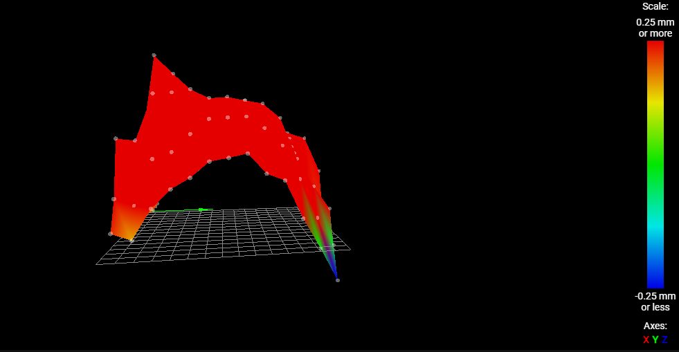
This will be the image of the height map I made for my printer
-
RE: The height map is not created correctlyposted in IR Height Sensor
This is the result of my printer, M122
M122 === Diagnostics === RepRapFirmware for Duet 2 WiFi/Ethernet version 3.3 (2021-06-15 21:44:54) running on Duet WiFi 1.02 or later + DueX5 Board ID: 0JD0M-9X6JA-JUNSN-6JKDJ-3S86N-TTRRU Used output buffers: 3 of 24 (18 max) === RTOS === Static ram: 23876 Dynamic ram: 75772 of which 0 recycled Never used RAM 14768, free system stack 178 words Tasks: NETWORK(ready,13.1%,244) HEAT(delaying,0.0%,314) Move(notifyWait,0.1%,319) DUEX(notifyWait,0.0%,24) MAIN(running,86.3%,449) IDLE(ready,0.4%,29), total 100.0% Owned mutexes: WiFi(NETWORK) === Platform === Last reset 00:02:48 ago, cause: software Last software reset at 2021-12-01 14:47, reason: User, GCodes spinning, available RAM 14768, slot 0 Software reset code 0x0003 HFSR 0x00000000 CFSR 0x00000000 ICSR 0x0041f000 BFAR 0xe000ed38 SP 0x00000000 Task MAIN Freestk 0 n/a Error status: 0x00 Aux0 errors 0,0,0 Step timer max interval 0 MCU temperature: min 30.3, current 31.7, max 32.1 Supply voltage: min 23.8, current 23.9, max 24.1, under voltage events: 0, over voltage events: 0, power good: yes Heap OK, handles allocated/used 0/0, heap memory allocated/used/recyclable 0/0/0, gc cycles 0 Driver 0: position 0, standstill, SG min/max not available Driver 1: position 0, standstill, SG min/max not available Driver 2: position 0, standstill, SG min/max not available Driver 3: position 0, standstill, SG min/max not available Driver 4: position 0, standstill, SG min/max not available Driver 5: position 0, standstill, SG min/max not available Driver 6: position 0, standstill, SG min/max not available Driver 7: position 0, standstill, SG min/max not available Driver 8: position 0, standstill, SG min/max not available Driver 9: position 0, standstill, SG min/max not available Driver 10: position 0 Driver 11: position 0 Date/time: 2021-12-01 14:50:40 Cache data hit count 4294967295 Slowest loop: 7.99ms; fastest: 0.17ms I2C nak errors 0, send timeouts 0, receive timeouts 0, finishTimeouts 0, resets 0 === Storage === Free file entries: 10 SD card 0 detected, interface speed: 20.0MBytes/sec SD card longest read time 0.9ms, write time 0.0ms, max retries 0 === Move === DMs created 83, maxWait 0ms, bed compensation in use: none, comp offset 0.000 === MainDDARing === Scheduled moves 0, completed moves 0, hiccups 0, stepErrors 0, LaErrors 0, Underruns [0, 0, 0], CDDA state -1 === AuxDDARing === Scheduled moves 0, completed moves 0, hiccups 0, stepErrors 0, LaErrors 0, Underruns [0, 0, 0], CDDA state -1 === Heat === Bed heaters = 0 -1 -1 -1, chamberHeaters = -1 -1 -1 -1 Heater 1 is on, I-accum = 0.0 === GCodes === Segments left: 0 Movement lock held by null HTTP is idle in state(s) 0 Telnet is idle in state(s) 0 File is idle in state(s) 0 USB is idle in state(s) 0 Aux is idle in state(s) 0 Trigger is idle in state(s) 0 Queue is idle in state(s) 0 LCD is idle in state(s) 0 Daemon is idle in state(s) 0 Autopause is idle in state(s) 0 Code queue is empty. === DueX === Read count 1, 0.36 reads/min === Network === Slowest loop: 15.86ms; fastest: 0.00ms Responder states: HTTP(0) HTTP(0) HTTP(0) HTTP(0) FTP(0) Telnet(0), 0 sessions HTTP sessions: 1 of 8 - WiFi - Network state is active WiFi module is connected to access point Failed messages: pending 0, notready 0, noresp 0 WiFi firmware version 1.25 WiFi MAC address 3c:61:05:d2:7a:4f WiFi Vcc 3.39, reset reason Turned on by main processor WiFi flash size 4194304, free heap 22472 WiFi IP address 192.168.1.102 WiFi signal strength -47dBm, mode 802.11n, reconnections 0, sleep mode modem Clock register 00002002 Socket states: 0 0 0 0 0 0 0 0 -
The height map is not created correctlyposted in IR Height Sensor
Hello, I am a beginner in electronics.
I've been struggling to make a height map for about a month and I don't think I can solve the problem, so I'm posting this.
I'm hoping that someone with more knowledge can help me.What information do I need to prepare first?
-
RE: What is the IR sensor installation process?posted in Duet Hardware and wiring
@t3p3tony Thank you for your reply.
Thank you for the clear site on C parameters.
I will refer to it. -
What is the IR sensor installation process?posted in Duet Hardware and wiring
Hello!
Please excuse the length of this article.
This is the first time I have installed a Z probe.
So I have done some preliminary research on my own by visiting some websites.
URL
[https://miscsolutions.wordpress.com/mini-height-sensor-board/]
[https://duet3d.dozuki.com/Wiki/Connecting_a_Z_probe#Section_Mode_Num_1]
[https://duet3d.dozuki.com/Wiki/M558]
I would like to know if there are any omissions in the process of installing the IR Sensor.
My printer type will be a Cartesian printer.
Please let us know if there are any errors.This is the sensor used in this project.
URL:[https://ja.aliexpress.com/item/1005001594649470.html?spm=a2g0s.9042311.0.0.10fe4c4duE7tdr]
This sensor is probably based on the DC42Mini height sensor.
Is it correct to wire the sensor as shown in the diagram?
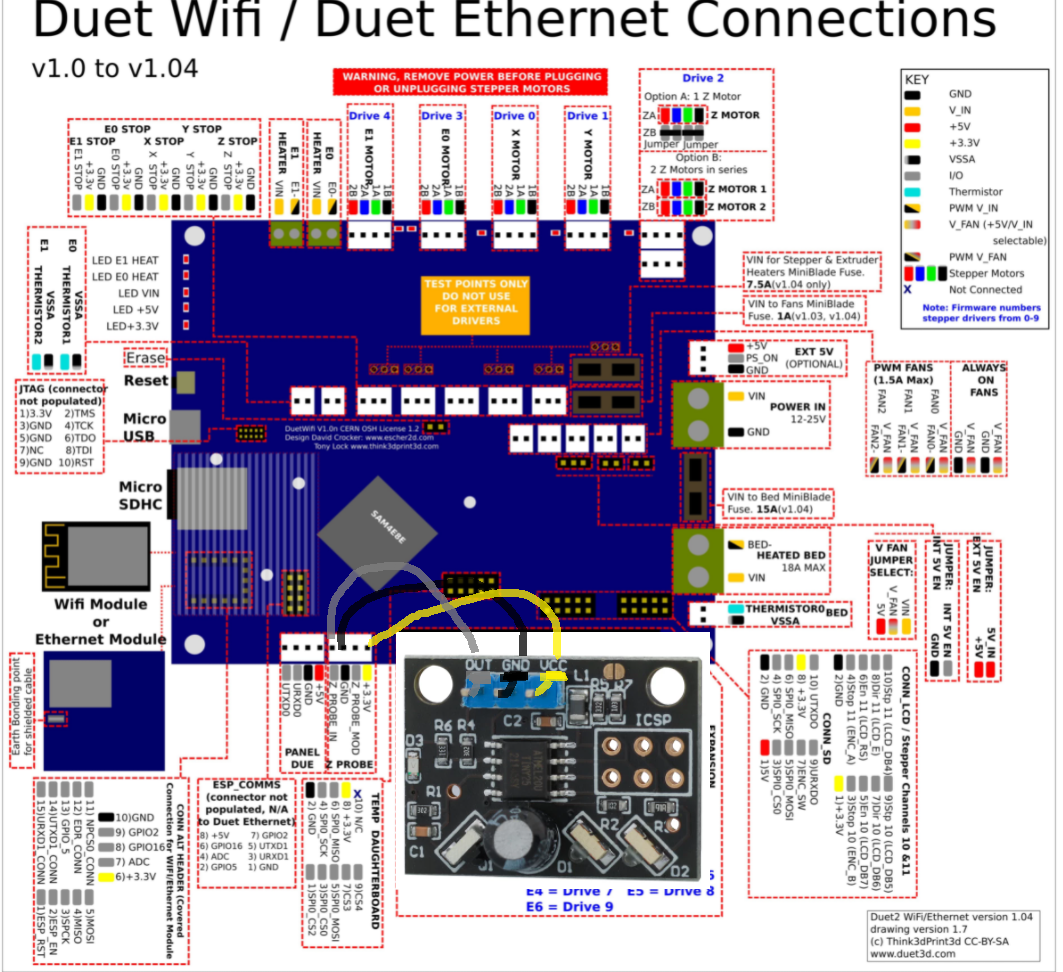
Next, I have a confirmation and a question about the G-code.
My version of Duet2 is here.RepRapFirmware for Duet 2 WiFi/Ethernet version 3.2.2 running on Duet WiFi 1.02 or laterWe are using Duet Web Control 3.3.0.
You will probably need to use the RRF3:M558 code.
Now config.g; Z-Probe M558 P0 H5 F120 T6000 ; disable Z probe but set dive height, probe speed and travel speed M557 X10:220 Y10:220 S20 ; define mesh gridThe modified config.g
; Z-Probe
M558 P1 C??? H10 F60 T60
M557 X10:220 Y10:220 S20
P1 : set to mode 1
H10 : Diving distance of the Z-probe * This is the first time I have set it up, so I set it high.I have a few questions.
I don't understand parameter C. What should I write in parameter C?
The F parameter was described as the probing speed. Does this mean that I can use the speed at which I normally print as the parameter value?
The T parameter was described as the speed of movement to and from the probe point. What is the difference between this and the F parameter?
※My printer is usually running at a maximum speed of 60mm/s. The speed that gives the best combination of accuracy and speed is 40mm/s.I have a question about platforms.
The platform I am using is a transparent glass plate with white masking tape on the back, which is placed on top of an aluminium plate.

Would it be better if I remove the masking tape and put a piece of black paper between the glass and the aluminium plate?Finally, the IR Sensor will be mounted close to the hot end. I don't currently have a silicone boot on my hot end. Should I add a silicone boot?
Thank you for reading to the end of this long article.
-
RE: What is the best way to destroy the Duet2 motor driver?posted in Using Duet Controllers
@dc42 Thank you for your reply!
I will lower the motor current to 600 with RRF and upload the zip file to Duet. -
RE: What is the best way to destroy the Duet2 motor driver?posted in Using Duet Controllers
@dc42 Thank you for your reply.
I am using only one Z axis. -
RE: What is the best way to destroy the Duet2 motor driver?posted in Using Duet Controllers
@veti Thank you for pointing this out.
I have no choice but to change the order of the cables because the cables I am using are twisted on the motor side and I do not have the terminals on the motor side. -
RE: What is the best way to destroy the Duet2 motor driver?posted in Using Duet Controllers
@phaedrux Thank you very much.
It was a short sentence, so typing it by hand was a big mistake.
Here is the result
M98 P "config.g"
HTTP is enabled on port 80
FTP is disabled
TELNET is disabled