Duet3D Logo Duet3D
    • Tags
    • Documentation
    • Order
    • Register
    • Login
    1. Home
    2. MihaiDesigns
    3. Posts
    • Profile
    • Following 0
    • Followers 3
    • Topics 8
    • Posts 22
    • Best 3
    • Controversial 0
    • Groups 0

    Posts made by MihaiDesigns

    • RE: Can this 5-axis FDM be configured with RRF?

      @droftarts said in Can this 5-axis FDM be configured with RRF?:

      @MihaiDesigns I don't think that kinematic type is supported in the 'normal' firmware, but there is work on-going on a version of RRF that, I think, might support it, which is @JoergS5's work: https://docs.duet3d.com/en/User_manual/Machine_configuration/Configuring_RepRapFirmware_for_a_Robot_printer

      The development discussion is here, though focus is more on palletised robots (4 axis arms, basically): https://forum.duet3d.com/topic/17421/robotic-kinematics/383
      This recent thread describes a machine where moves in BC move XYZ too, I think similar to your requirement: https://forum.duet3d.com/topic/35865/voron5x-with-rtcp/

      Hope that helps!

      Ian

      I see that the robot printer still implements only AC and BC (used for the Voron5X).
      Since I need this for a PoC, I guess one somewhat easy solution is to write a gcode processor that calculates the XYZ compensation when rotating A and B. I mean it would anyways be some generated gcode to print basic shapes with steep overhangs (it's one of the reasons I wanted the rotating axes).
      In which case the firmware needs to move some extra axes I suppose, like G1 X Y Z U V? Then it would move all axes at the same time? And my gcode processor segments the moves into very short segments (0.2mm in length or so). Am I going the right direction here?

      posted in CNC
      MihaiDesignsundefined
      MihaiDesigns
    • Can this 5-axis FDM be configured with RRF?

      Posting here since it's 5 axis, but this is for a 3D printer project.
      Only focusing on the rotational axes in this topic, I want to build the illustrated design so that the nozzle can rotate. 91de4d8b-afb3-4454-95f3-c2bd1b9ae5ac-image.png

      At rest position the axis closest to the end effector is parallel to the Y axis, and the next one is parallel to the X axis. Both have offsets (one relative to the other and to the end effector).
      XY axes are CoreXY, Z connected to the carriage, fixed bed. So reading the documentation this would be a XYZAB or something like that? And there should be some way to configure them using M669, but am not sure the firmware has support for all the parameters. It mostly talks about AC/BC configurations where offsets are supported, but doesn't mention offsets for AB and I couldn't find a good example configuration to get inspiration from.

      What I would like to get from the firmware is the IK solving so that when the g-code asks for a motion that involves A and B axes rotation, it will adjust the XYZ position so that the end effector stays in the same place with relation to the bed, but changes angles.

      I'm asking here if this is supported by the firmware so that I don't invest time in building a device that cannot be configured.

      Edit: here are the two vectors I'm wondering how to configure. be3f6702-8a3f-4339-becf-5417e925880c-image.png

      posted in CNC
      MihaiDesignsundefined
      MihaiDesigns
    • Bad surface finish

      PXL_20231024_141157336.jpg PXL_20231024_141151213.jpg PXL_20231024_141133665.jpg PXL_20231024_141125548.jpg

      Left: 1K acceleration without IS.
      Center: 1K acceleration with IS.
      Right: 3K acceleration with IS.
      Printing at 150mm/s speed on a CoreXY about the size of a 400mm cube build volume.

      Is this normal?
      Coextrusion filament. Looks a bit like silk, very shiny, so artifacts are emphasized.
      IS, PA, and jerk are already calibrated (at least to some extent).
      Running RRF 3.5.0-rc.1. (I haven't tried any other version).

      It looks better if I print much slower, but still, the prints look very bad to me. I'm hoping there's a way to improve the surface considerably.

      posted in Tuning and tweaking
      MihaiDesignsundefined
      MihaiDesigns
    • RE: Very low acceleration during printing

      @droftarts indeed it was the E jerk. I had it set to 4. I assumed a high E acceleration would take care of it, but it seems not.

      Edit: For clarification, I meant 4mm/s, which is 240mm/min.

      posted in Tuning and tweaking
      MihaiDesignsundefined
      MihaiDesigns
    • RE: Very low acceleration during printing

      @droftarts yes, I did check M204 and the firmware reports it correctly. X, Y, and E are all set to 15K acceleration.

      posted in Tuning and tweaking
      MihaiDesignsundefined
      MihaiDesigns
    • Very low acceleration during printing

      I'm running a speed test and trying 15K acceleration for infill print moves. X, Y, and E axes all have acceleration limit set to 15K, and print moves are set to 15K acceleration. The interface reports the correct settings. Printing speed is close to 300mm/s. It looks right in the slicer preview (PrusaSlicer). There's no minimum layer time set.

      However, during printing it looks more like under 2000 acceleration. I can't figure out why.

      posted in Tuning and tweaking
      MihaiDesignsundefined
      MihaiDesigns
    • RE: DWC not loading on iPad

      @Phaedrux thanks! I'm running iOS 12. I'll try downgrading the DWC.

      posted in Duet Web Control
      MihaiDesignsundefined
      MihaiDesigns
    • RE: DWC not loading on iPad

      It's an older iPad. I just upgraded to iOS 12.5.7. Still the same issue.

      posted in Duet Web Control
      MihaiDesignsundefined
      MihaiDesigns
    • RE: Issues configuring firmware

      Update: I got sensorless homing working on all 3 axes.
      Someone suggested adjusting stealthchop/spreadcycle like this: M569 P0.3 V40 D3 and it fixed one of the axes. For the Z axis with small motors I had to go back and forth with stall sensitivity and speed. Same for the remaining axis, basically trying random speeds and sensitivities until it worked. It took a while, but it worked eventually.

      @fcwilt thanks for the help.

      Still got that probing offset thing to fix, but that's tomorrow.

      posted in Tuning and tweaking
      MihaiDesignsundefined
      MihaiDesigns
    • RE: Issues configuring firmware

      I tested firmware version 3.4.6 (updated all boards) and sensorless homing is still not working. I suspect I have an error in my configuration but can't figure out what it is.

      posted in Tuning and tweaking
      MihaiDesignsundefined
      MihaiDesigns
    • RE: Issues configuring firmware

      @fcwilt thank you!

      posted in Tuning and tweaking
      MihaiDesignsundefined
      MihaiDesigns
    • RE: Issues configuring firmware

      I wonder if it has something to do with the 3.5.0 RC1 firmware. I'll try a more stable version.

      posted in Tuning and tweaking
      MihaiDesignsundefined
      MihaiDesigns
    • RE: Issues configuring firmware

      @fcwilt the thing is I'd like to avoid adding 6 more switches and wires. Plus, two of the axes home at the far end from the motor position, so not even the same wire path. I used sensorless homing in Marlin on various printers. It shouldn't be hard to configure.

      posted in Tuning and tweaking
      MihaiDesignsundefined
      MihaiDesigns
    • DWC not loading on iPad

      Duet Web Control not loading on iPad.

      Running Duet 3 Mini5+ WiFi.
      DWC is loading on Windows PC and on Android phone (same WiFi).
      Other web pages are loading on the iPad.
      The DWC interface appears to be loading, the title "Duet Web Control" shows up in the title bar, but the page content remains empty.
      I tested on both Safari and Chrome with the same result.
      The iPad is an old model but seems to be working fine.
      Edit: I did try restarting the printer, the router, and the iPad.

      I have no idea what to try next. I was hoping to use this iPad as a screen for the Duet-powered 3D printer.

      posted in Duet Web Control
      MihaiDesignsundefined
      MihaiDesigns
    • RE: Issues configuring firmware

      @fcwilt thanks for the answer.

      I solved the extra axis endstop homing. On Z probing I'll have to read more documentation first.

      Sensorless homing still not working.
      I have 3 axes running 3, 2, and 1 motor respectively. Sensorless homing is not working for any of them. The last two use Nema17 motors, not geared. They are all connected to the Mini 5+ board, two via the small TMC expansion board.
      Here's the relevant config for one of the axes (U) running just one motor:

      config.g

      M569 P0.5 S1
      M584 U0.5
      M350 U16 I1
      M92 U160
      M566 U600
      M203 U24000
      M201 U2000
      M906 U800
      
      M915 P5 S-120 R0 ; I set the sensitivity abnormally low and it still doesn't trigger. Also fails for S0
      
      M208 U0 S1                                        ; set axis minima
      M208 U550 S0                                     ; set axis maxima
      
      M574 U1 S3 ; sensorless endstop
      

      homeu.g

      G91               
      G1 H2 U10 F6000    
      G1 H1 U-30 F1800  ; moving just a little bit for testing (axis starts in the homed position anyways)
      G92 U0            
      
      posted in Tuning and tweaking
      MihaiDesignsundefined
      MihaiDesigns
    • Issues configuring firmware

      I'm configuring a CoreXY 3D printer with an accessory that runs additional axes. (First time configuring a Duet build). Running RRF 3.5.0 RC1 as I will need some of the features there.

      Using Duet 3 Mini 5+ with the 2 stepper expansion board, 3HC expansion, and toolboard. So far the heated beds work (4 zones), the extruder works (toolboard), X and Y axes work and are homing (endstop switches).

      I could use some help fixing the following issues:

      1. I can't get the sensorless homing to work on the Z axis (bed moves on Z via belts and small geared motors). It reaches the end and keeps going trying to move past. I have 3 independent motors connected to ports 0,1,2. I want to home at the bottom. See end of config below.

      M569 P0.0 S0
      M569 P0.1 S0
      M569 P0.2 S1
      M584 X1.0 Y1.1 Z0.0:0.1:0.2 E121.0                        ; set drive mapping
      M350 X16 Y16 Z16 E16 I1                                   ; configure microstepping with interpolation
      M92 X160.00 Y160.00 Z800.00 E710.00                       ; set steps per mm
      M566 X900.00 Y900.00 Z60.00 E120.00                       ; set maximum instantaneous speed changes (mm/min)
      M203 X36000.00 Y36000.00 Z3600.00 E1800.00                ; set maximum speeds (mm/min)
      M201 X2000.00 Y2000.00 Z300.00 E2000.00                   ; set accelerations (mm/s^2)
      M906 X2000 Y2000 Z600 E600 I30                            ; set motor currents (mA) and motor idle factor in per cent
      M84 S30                                                   ; Set idle timeout
      
      ; stall detection
      M915 P0.0 S0 R1 H400
      M915 P0.1 S0 R1 H400
      M915 P0.2 S0 R1 H400
      
      ; axis limits
      M208 X-3 Y0 Z0 S1                                         ; set axis minima
      M208 X370 Y400 Z382 S0                                    ; set axis maxima
      

      For homing I call G1 H1 Z100 F3600.
      I tried M915 P0.x S0 alone, even tried S-50 which is super sensitive and it still fails to trigger. I understand that R1 should log the event, but am not sure where it would get logged. Also tried setting a low motor current to 200mA. Running out of ideas to try.

      2. I cannot home a custom axis. I have an axis called W on an accessory. I can move the axis with G1 Wxx command. There is an endstop switch. I'd like to home that axis using the switch and I can't figure out how. I have the config below and am not sure the last line is allowed:

      M569 P0.6 S0
      M584 U0.5 V0.3:0.4 W0.6                                   ; set drive mapping
      M350 U16 V16 W16 I1                                       ; configure microstepping with interpolation
      M92 U160 V160 W36                                         ; set steps per mm
      M566 U600 V600 W600                                       ; set maximum instantaneous speed changes (mm/min)
      M203 U24000 V12000 W12000                                 ; set maximum speeds (mm/min)
      M201 U2000 V2000 W300                                     ; set accelerations (mm/s^2)
      M906 U1000 V1000 W1000                                    ; set motor currents (mA) and motor idle factor in per cent
      M208 U0 V0 W-90 S1                                        ; set axis minima
      M208 U550 V550 W90 S0                                     ; set axis maxima
      M574 W2 S1 P"^1.io2.in"                                   ; configure switch-type (e.g. microswitch) endstop 
      

      Last line is exactly the same format as the ones for the X and Y endstop switches (M574 X1 S1 P"^1.io0.in").
      I tried homing with something like G1 H2 W200 F360 but it reaches the endstop and keeps trying to move past. I did check the endstop wiring.
      Looking at the documentation, the last line in the code above might not be allowed. M572 specifies parameters X, Y, Z, P, S, K. There's no mention of custom axes such as W. What is the best way to home a custom axis?
      Additionally, I have other custom axes (U and V) which will require sensorless homing, but am hoping to fix the sensorless homing on the Z first.

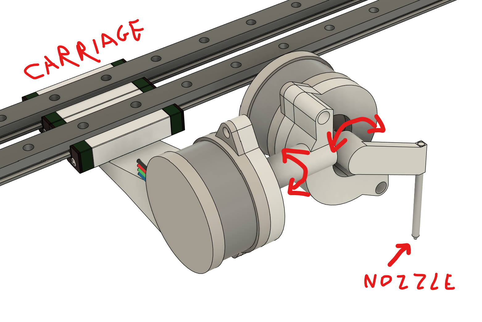
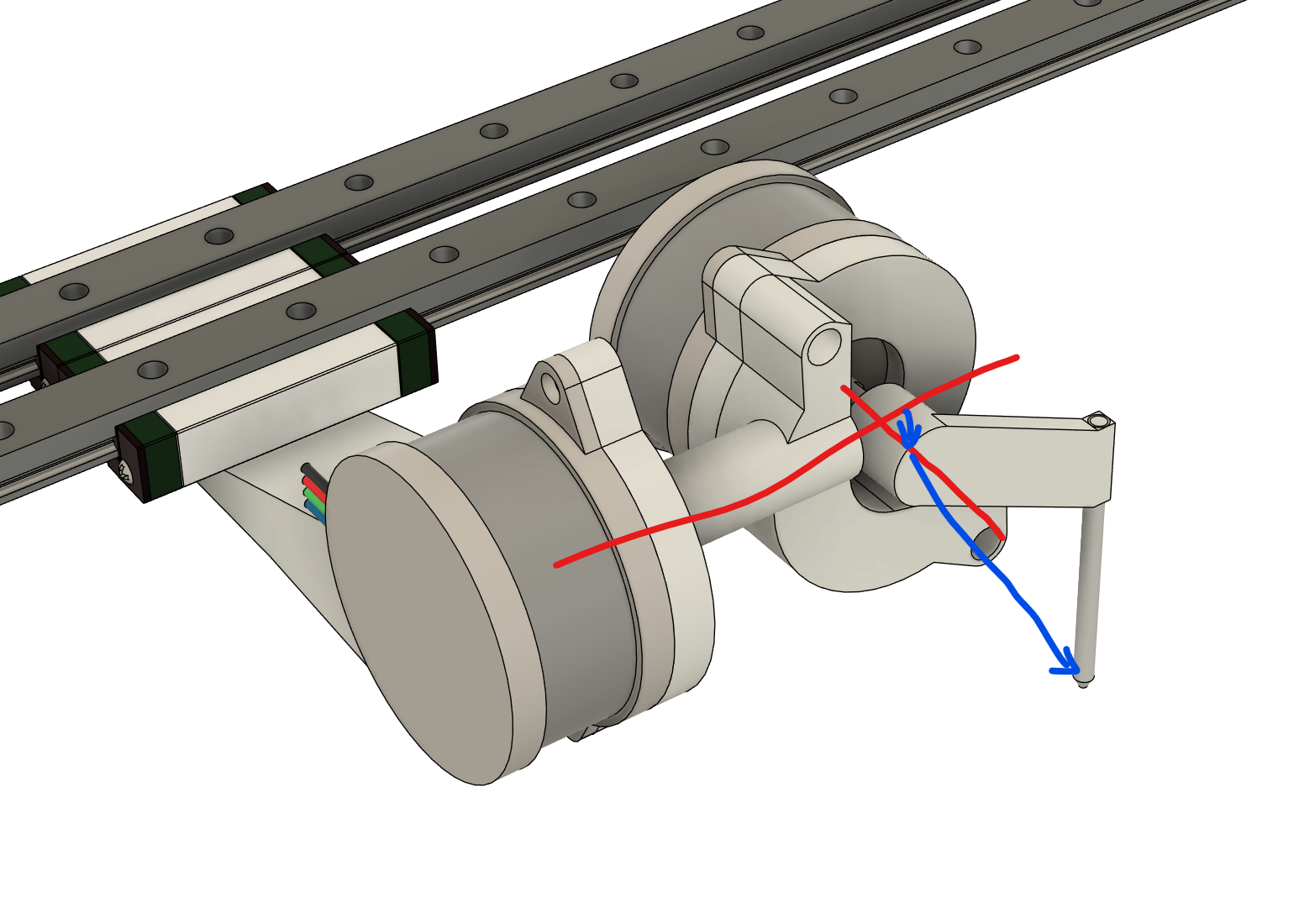
      3. Ideal mesh leveling probe configuration. I have a custom probe, similar in concept to the Klicky probe. Basically a microswitch that attaches via magnets to the underside of the extruder. I can load/unload(park) it. The probe triggers about 14.5mm below the nozzle Z height. I got it working by calling code below after loading the probe:

      G0 Z16
      M557 X10:360 Y0:350 S70  
      G29 S0
      

      (I manually "homed" the Z axis so it sort of knows where it is roughly).
      However, I read in the documentation that I should first establish a Z=0 datum first. So I ran the code:

      G0 Z16 ; lower bed
      G0 X182 Y182 F36000
      M98 P"/macros/probe-load.g"
      G0 X182 Y182 F36000 
      
      G30    ; Establish a Z=0 datum
      G31 P500 X0 Y22.5 Z2   
      
      M557 X10:360 Y0:350 S70  
      
      G29 S0
      

      If I do that, the mesh probing starts at a very high position (~15-20mm above the bed) and slowly moves the bed until it touches. It does this for every probing point. It takes forever! I with it used the Z2 probing distance as instructed.
      I'm not sure how to improve this. I could skip the Z=0 datum, but I feel like there should be a better way.

      I'm also starting toying with G30 S3 (as I run independent motors and kinematic coupled bed) but wanted to finish fixing the homing first.

      Cheers!

      posted in Tuning and tweaking
      MihaiDesignsundefined
      MihaiDesigns
    • RE: Additional external MOSFET without using a heater port

      @dc42 awesome, thank you!

      posted in Duet Hardware and wiring
      MihaiDesignsundefined
      MihaiDesigns
    • Additional external MOSFET without using a heater port

      I'm trying to power an external MOSFET (the generic inexpensive HA210NO6-based extension module) without using a heater port. I have more heaters than heater ports: I'm running a bed with 4 heating zones and 3 additional heaters for other things (think of them as parked hotends that need preheating), aside from the hotend which is running a tool board. Using the boards: Duet 3 Mini 5+ and 3HC. I count 6 power outputs and I need a 7th.

      I was going to drive the external MOSFET module via an IO pin, but I just realized that this board requires at least 6.5V (determined using a lab PSU). Do you have any ideas on how I could connect this MOSFET module to my Duet boards without using the power outputs? Any ideas are welcome.

      posted in Duet Hardware and wiring
      MihaiDesignsundefined
      MihaiDesigns
    • PanelDue cable extension

      I need about 2 meters of cable between the display and the board. I read that I can extend the 4p cable to 2m. Ideally, I'd be able to use the SD card; for that, I need the 10p cable (or so I understand). Would it work to extend that cable as well to 2 meters? I suppose I could give up the SD card support if it's too much trouble, but wanted to check here first.

      posted in Duet Hardware and wiring
      MihaiDesignsundefined
      MihaiDesigns
    • PT100 daughter board 3 wires wiring

      First time using PT100 sensors.
      Docs mention support for 2, 3, and 4 wires. Mine have 3 wires. There are instructions for using 2 wires and 4 wires. Not sure how to go about using 3 wires.
      Docs: https://docs.duet3d.com/User_manual/Connecting_hardware/Temperature_connecting_PT100

      posted in Duet Hardware and wiring
      MihaiDesignsundefined
      MihaiDesigns