I have a standard V6 hot end running on a 1LC toolboard. I would like to switch to a V6 Revo Six hot end. Can I still use this toolboard or do I have to change to the roto toolboard.
Posts made by ortondale
-
Toolboard1LC v Roto Toolboardposted in Duet Hardware and wiring
-
RE: Z scanning probe point errorposted in Duet Hardware and wiring
@ortondale
Hi Thanks for the help, up a running ok.
Looks like a new bed plate called for! -
RE: Z scanning probe point errorposted in Duet Hardware and wiring
@ortondale
What is the effective scanning distance from the bed? With the present scanning the coil is 4mm above the bed, is this distance to great.
Also I notice I’m not using the M558.1 command, not sure the effect this has -
RE: Z scanning probe point errorposted in Duet Hardware and wiring
@ortondale
Specified K0 K1 in G29, G30, G31 commands and removed M375 in config.g
Reset the probe area to within the probe reach.
The bed scanned without any error messages showing 324 points but still no height readings; Z-Probe
M950 S0 C"121.io0.out"
M558 P9 C"121.io0.in" H5 F120 T3000 A5 S0.05 B1
;M558 H30
G31 K0 P500 X30 Y0 Z1.099
;M557 X5:290 Y2:260 S38; Scanning Z Probe
M558 K1 P11 C"120.i2c.ldc1612" F36000 T36000
M308 A"SZP coil" S10 Y"thermistor" P"120.temp0"
G31 K1 Z1.9 X15.796 Y-21.5
M558.2 K1 S16 R131621
M557 X28.7:259.9 Y5:236.2 S13.6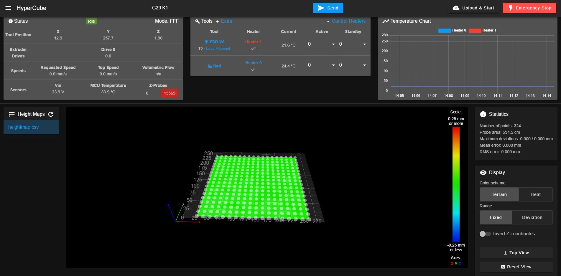
Does this prove that the coil and board are working ok and the error is in the coding?
-
RE: Z scanning probe point errorposted in Duet Hardware and wiring
@Phaedrux ;
Hi
Config files ect: RepRap Firmware and DWC ver 3.5.2
Define mesh M557 X and Y is the position of the coil probe, G31 X and Y being nozzle offset to probe coil.Configuration file for Duet 3 Mini 5+ (firmware version 3.3)
; executed by the firmware on start-up
;
; generated by RepRapFirmware Configuration Tool v3.3.16 on Thu Jul 27 2023 15:43:08 GMT+0200 (Central European Summer Time); General preferences
G90 ; send absolute coordinates...
M83 ; ...but relative extruder moves
M550 P"HyperCube" ; set printer name
M669 K1 ; select CoreXY modeG4 S2 ; Wait a moment for the CAN expansion boards to start
; Network
M552 S1 ; enable network
M586 P0 S1 ; enable HTTP
M586 P1 S0 ; disable FTP
M586 P2 S0 ; disable Telnet; Drives
M569 P0.0 S0 ; physical drive 0.0 goes backward (left hand X Y axis motor)
M569 P0.1 S0 ; physical drive 0.1 goes backward (right hand X Y axis motor)
M569 P0.2 S0 ; physical drive 0.2 goes backward (left hand Z axis motor)
M569 P0.4 S0 ; physical drive 0.4 goes backward (right hand Z axis motor)
M569 P121.0 S0 ; physical drive 121.0 goes backwards (Toolboard) (extruder motor)
M584 X0.0 Y0.1 Z0.2:4 E121.0 ; set drive mapping
M350 X16 Y16 Z16 E16 I1 ; configure microstepping with interpolation
M92 X80.00 Y80.00 Z400.00 E415.00 ; set steps per mm
M566 X600.00 Y600.00 Z50.00 E600.00 ; set maximum instantaneous speed changes (mm/min)
M203 X10000.00 Y10000.00 Z180 E5000 ; set maximum speeds (mm/min)30000
M201 X2000 Y2000 Z650 E3200 ; set accelerations (mm/s^2) Moded from 20 to 200
M906 X1150 Y1150 Z800 E560 I60 ; set motor currents (mA) and motor idle factor in per cent ( moded X Y from 900 to 700) (E 500 to 400)
M84 S30 ; Set idle timeout; Axis Limits
M208 X0 Y0 Z0 S1 ; set axis minima
M208 X290 Y260 Z280 S0 ; set axis maxima; Endstops
M574 X1 S1 P"121.io2.in" ; configure switch-type (e.g. microswitch) endstop for low end on X via pin 121.io2.in
M574 Y2 S1 P"io6.in" ; configure switch-type (e.g. microswitch) endstop for high end on Y via pin io6.in
M574 Z1 S2 ; configure Z-probe endstop for low end on Z; Z-Probe
M950 S0 C"121.io0.out" ; create servo pin 0 for BLTouch
M558 P9 C"121.io0.in" H5 F120 T3000 A5 S0.05 B1 ; set Z probe type to bltouch and the dive height + speeds
;M558 H30 ;*** Remove this line after delta calibration has been done and new delta parameters have been saved
G31 P500 X30 Y0 Z1.099 ; set Z probe trigger value, offset and trigger height
;M557 X5:290 Y2:260 S38 ; define mesh grid; Scanning Z Probe
M558 K1 P11 C"120.i2c.ldc1612" F36000 T36000 ; K1 parameter configures it as Z probe 1 so as to leave primary probe Bltouchh as 0
M308 A"SZP coil" S10 Y"thermistor" P"120.temp0" ; thermistor on coil
G31 K1 Z1.9 X15.796 Y-21.5 ; define probe 1 offset and trigger height
M558.2 K1 S16 R131621 ; set drive current and reading offset
M557 X1.5:260 Y5:255 S13.6 ; define mesh grid for probe 1 (overwrites probe 0 mesh grid); Heaters
M308 S0 P"temp0" Y"thermistor" T100000 B4725 C7.06e-8 ; configure sensor 0 as thermistor on pin temp0
M950 H0 C"out0" T0 ; create bed heater output on out0 and map it to sensor 0
M307 H0 R0.198 K0.244:0.000 D4.63 E1.35 S1.00 B0 ; disable bang-bang mode for the bed heater and set PWM limit
M140 H0 ; map heated bed to heater 0
M143 H0 S70 ; set temperature limit for heater 0 to 70C
M308 S1 P"121.temp0" Y"thermistor" T100000 B4725 C7.06e-8 ; configure sensor 1 as thermistor on pin 121.temp0
M950 H1 C"121.out0" T1 ; create nozzle heater output on 121.out0 and map it to sensor 1
M307 H1 R1.840 K0.414:0.000 D5.70 E1.35 S1.00 B0 V24.2 ; disable bang-bang mode for heater and set PWM limit
M143 H1 S280 ; set temperature limit for heater 1 to 280C; Fans
M950 F0 C"121.out1" Q500 ; create fan 0 on pin 121.out1 and set its frequency
M106 P0 S0 H-1 ; set fan 0 value. Thermostatic control is turned on
M950 F1 C"121.out2" Q500 ; create fan 1 on pin 121.out2 and set its frequency
M106 P1 S1 H1 T45 ; set fan 1 value. Thermostatic control is turned on; Tools
M563 P0 S"E3D V6" D0 H1 F0 ; define tool 0
G10 P0 X0 Y0 Z0 ; set tool 0 axis offsets
G10 P0 R0 S0 ; set initial tool 0 active and standby temperatures to 0C
M955 P121.0 I52 ; Configure Accelerometer
; Tuning
;M593 P"ZVDDD" F60 S0 ; accelerometer setting
;M572 D0 S0.04 ;pressure advance setting
; Accelerometer Settings
; Custom settings are not defined; Miscellaneous
M501 ; load saved parameters from non-volatile memory
M911 S10 R11 P"M913 X0 Y0 G91 M83 G1 Z3 E-5 F1000" ; set voltage thresholds and actions to run on power loss
M375 ; load bed mesh
;G29 S1 ; load bed mesh9/10/2024, 8:51:07 PM M98 P"config.g"
HTTP is enabled on port 80
FTP is disabled
TELNET is disabled
Warning: the height map was loaded when the current Z=0 datum was not determined by probing. This may result in a height offset.
9/10/2024, 8:50:21 PM m122
=== Diagnostics ===
RepRapFirmware for Duet 3 Mini 5+ version 3.5.2 (2024-06-11 17:14:16) running on Duet 3 Mini5plus WiFi (standalone mode)
Board ID: M8JRG-KQ6KL-K65J0-409NL-2B02Z-RK245
Used output buffers: 3 of 40 (22 max)
=== RTOS ===
Static ram: 103368
Dynamic ram: 122864 of which 0 recycled
Never used RAM 12232, free system stack 148 words
Tasks: NETWORK(2,nWait 7,14.6%,203) LASER(5,nWait 7,0.0%,169) HEAT(3,nWait 6,0.0%,350) Move(4,nWait 6,0.1%,278) CanReceiv(6,nWait 1,0.1%,796) CanSender(5,nWait 7,0.0%,336) CanClock(7,delaying,0.0%,348) TMC(4,nWait 6,0.9%,67) MAIN(1,running,83.4%,665) IDLE(0,ready,0.1%,29) AIN(4,delaying,0.9%,259), total 100.0%
Owned mutexes:
=== Platform ===
Last reset 00:11:10 ago, cause: software
Last software reset at 2024-09-10 20:39, reason: User, Gcodes spinning, available RAM 12184, slot 2
Software reset code 0x0003 HFSR 0x00000000 CFSR 0x00000000 ICSR 0x00000000 BFAR 0xe000ed38 SP 0x00000000 Task MAIN Freestk 0 n/a
Error status: 0x00
MCU revision 3, ADC conversions started 670622, completed 670622, timed out 0, errs 0
MCU temperature: min 34.5, current 34.9, max 36.2
Supply voltage: min 23.6, current 23.8, max 23.9, under voltage events: 0, over voltage events: 0, power good: yes
Heap OK, handles allocated/used 99/0, heap memory allocated/used/recyclable 2048/12/12, gc cycles 0
Events: 0 queued, 0 completed
Driver 0: standstill, SG min 0, read errors 0, write errors 1, ifcnt 88, reads 35260, writes 15, timeouts 0, DMA errors 0, CC errors 0
Driver 1: standstill, SG min 0, read errors 0, write errors 1, ifcnt 89, reads 35260, writes 15, timeouts 0, DMA errors 0, CC errors 0
Driver 2: standstill, SG min 0, read errors 0, write errors 1, ifcnt 83, reads 35259, writes 15, timeouts 0, DMA errors 0, CC errors 0
Driver 3: standstill, SG min 0, read errors 0, write errors 1, ifcnt 54, reads 35264, writes 10, timeouts 0, DMA errors 0, CC errors 0
Driver 4: standstill, SG min 0, read errors 0, write errors 1, ifcnt 80, reads 35260, writes 15, timeouts 0, DMA errors 0, CC errors 0
Driver 5: not present
Driver 6: not present
Date/time: 2024-09-10 20:50:17
Cache data hit count 1300134961
Slowest loop: 33.95ms; fastest: 0.15ms
=== Storage ===
Free file entries: 20
SD card 0 detected, interface speed: 22.5MBytes/sec
SD card longest read time 3.6ms, write time 2.8ms, max retries 0
=== Move ===
DMs created 83, segments created 4, maxWait 14712ms, bed compensation in use: mesh, height map offset 0.000, max steps late 0, min interval 0, bad calcs 0, ebfmin 0.00, ebfmax 0.00
no step interrupt scheduled
Moves shaped first try 0, on retry 0, too short 0, wrong shape 0, maybepossible 0
=== DDARing 0 ===
Scheduled moves 357, completed 357, hiccups 0, stepErrors 0, LaErrors 0, Underruns [0, 0, 0], CDDA state -1
=== DDARing 1 ===
Scheduled moves 0, completed 0, hiccups 0, stepErrors 0, LaErrors 0, Underruns [0, 0, 0], CDDA state -1
=== Heat ===
Bed heaters 0 -1 -1 -1, chamber heaters -1 -1 -1 -1, ordering errs 0
=== GCodes ===
Movement locks held by null, null
HTTP is idle in state(s) 0
Telnet is idle in state(s) 0
File is idle in state(s) 0
USB is idle in state(s) 0
Aux is idle in state(s) 0
Trigger is idle in state(s) 0
Queue is idle in state(s) 0
LCD is idle in state(s) 0
SBC is idle in state(s) 0
Daemon is idle in state(s) 0
Aux2 is idle in state(s) 0
Autopause is idle in state(s) 0
File2 is idle in state(s) 0
Queue2 is idle in state(s) 0
Q0 segments left 0, axes/extruders owned 0x0000007
Code queue 0 is empty
Q1 segments left 0, axes/extruders owned 0x0000000
Code queue 1 is empty
=== CAN ===
Messages queued 6443, received 19161, lost 0, errs 0, boc 0
Longest wait 2ms for reply type 6053, peak Tx sync delay 60, free buffers 26 (min 24), ts 3353/3352/0
Tx timeouts 0,0,0,0,0,0
=== Network ===
Slowest loop: 11.50ms; fastest: 0.00ms
Responder states: MQTT(0) HTTP(0) HTTP(0) HTTP(0) HTTP(0) FTP(0) Telnet(0)
HTTP sessions: 1 of 8
=== WiFi ===
Interface state: active
Module is connected to access point
Failed messages: pending 0, notrdy 0, noresp 0
Firmware version 2.1.0
MAC address c4:5b:be:ce:95:c3
Module reset reason: Power up, Vcc 3.46, flash size 2097152, free heap 42632
WiFi IP address 192.168.1.246
Signal strength -44dBm, channel 1, mode 802.11n, reconnections 0
Clock register 00002001
Socket states: 0 0 0 0 0 0 0 0 -
RE: Z scanning probe point errorposted in Duet Hardware and wiring
@oliof Hi, running latest ver. 3.5.2
-
Z scanning probe point errorposted in Duet Hardware and wiring
Z scanning probe point error
Finally got the Z probe to scan the bed but not returning a reading. At each probe point the message
(Skipping grid point X=# Y=# because the Z probe cannot reach it). The height map shows 0 at each point across the bed. Can someone point me in the right direction? -
Scanning Z probe coils with Bltouchposted in Duet Hardware and wiring
About to add Z probe scanning on next upgrade
At Formnect 23 Tony Lock introduced the SZP board along with three coil types, one of which was a design to allow a Bltouch to probe through the centre of the coil before scanning the bed. The other two coil types are the ones currently being supplied with the board. Can anybody tell me if the Bltouch coil is available, if so where from, or did Duet drop the idea.
If using one of the supplied coils is it workable to drill a hole in the centre and probe through the coil. -
Scanning Z probe coilsposted in General Discussion
Scanning Z probe coils
About to add Z probe scanning on next upgrade
At Formnect 23 Tony Lock introduced the SZP board along with three coil types, one of which was a design to allow a Bltouch to probe through the centre of the coil before scanning the bed. The other two coil types are the ones currently being supplied with the board. Can anybody tell me if the Bltouch coil is available, if so where from, or did Duet drop the idea.
If using one of the supplied coils is it workable to drill a hole in the centre and probe through the coil. -
RE: Parts fan always onposted in Duet Hardware and wiring
@ortondale Hi Phaedrux
I don’t want it to run all the time
I require it to run say on second or third layer. Should the black negative be on pin out1 for this to happen or on out1.tach. -
Parts fan always onposted in Duet Hardware and wiring
Sorry to bother you kind folks again
On testing my new install with Duet3 Mini5+ and toolboard 1LC v1.3, I find the parts cooling fan run continuously from power up. The hot end fan is ok coming on at temp 45c.Connected fan to OUT5 on main board and it worked ok, coming on at second layer.
Have I got the wrong pins connected on the toolbord?
Should it be +VOUT and out1 pins not GND and +VOUTToolboard
![DSCN1733[1].jpg](/assets/uploads/files/1690801939976-dscn1733-1.jpg)
Config.g
; Fans
M950 F0 C"121.out1" Q500
M106 P0 S0 H-1
M950 F1 C"121.out2" Q500
M106 P1 S1 H1 T45Also in Web Controller both fans show up, but when I adjust /move one slider the other slider moves the same.
Any advice would be appreciated. -
RE: Lost WiFi communicationposted in Duet Hardware and wiring
You are right about the SD card. Had taken it out to check this allusive macro file that might cause problems and forgot to put it back.
I have had another go at making sense of the Yat readings and I think I’ve found the problem.
I have two internet speeds with slightly differing address. It seems the board doesn’t like the 5 GHz address. When I entered the slow speed address the board connected ok.
Now just waiting to see how long it stays connected. -
RE: Lost WiFi communicationposted in Duet Hardware and wiring
Phaedrux
Thanks for pointing to respond guide
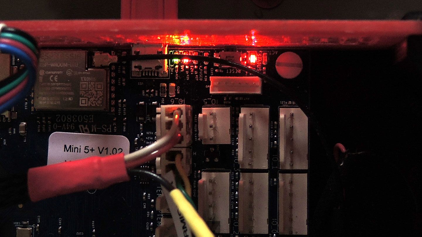
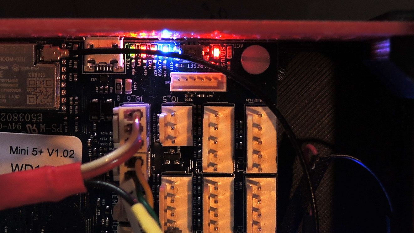
As you can see from photo´s all LED conform to guide, with red status flashing
On USB power 12v, V fused and ACT LED not on. WiFi ESP not on
On 24v power ACT LED not on. WiFi ESP not on.
Question : When is the green LED for the WiFi modual supposed to be active, is it when power is supplied, or when the modual receives a signal. At the moment this LED does not light upUSB Cable
24v Power
Port reported in Device Manager when connected to USB
Connected to YAT using the same port terminal.Result of commands sent in YAT
M115
FIRMWARE_NAME: RepRapFirmware for Duet 3 Mini 5+ FIRMWARE_VERSION: 3.4.5 ELECTRONICS: Duet 3 Mini5plus WiFi FIRMWARE_DATE: 2022-11-30 19:41:16M552 S-1
Error: M552: Network-related commands are not supported when using an attached Single Board ComputerFirst time this has shown up. Only board connected is a Toolboard 1LC.
Duet3 Mini5+ V1.02 Toolboard V1.3, Both purchased six weeks ago.
Your thoughts appreciated
-
RE: Lost WiFi communicationposted in Duet Hardware and wiring
@KenW Just checked my copy and have the same macro file.
Are you saying this deletes the config.g file? -
RE: Lost WiFi communicationposted in Duet Hardware and wiring
@KenW Went through the set up procedure for new board while connected to USB to PC as per Duet instructions, using saved copy RepRap Configurator files.
Now it doesn’t even respond in YAT -
Lost WiFi communicationposted in Duet Hardware and wiring
Duet 3 Mini 5+ WiFi
Just installed new duet3 WiFi board. After a couple of days lost connection and had to reload files over USB.
Again today loss connection, but this time unable to connect over USB.
Noticed that the ESP Led next to the WiFi module is not illuminated as it should be. Have I to assume that the module has given up. All other Led on the board are on ok.
If so how do I go about getting it sorted. -
RE: Hoe to invert endstopsposted in General Discussion
@deckingman
Many thanks for the info works a treat -
Hoe to invert endstopsposted in General Discussion
Core XY
Duet 3 mini 5+ firmware 3.4.5
ToolBoard 1LC
Just upgraded printer with above boards replacing a Duet 2 Maestro set up.
At the same time upgraded to latest firmware
Require home to be back left corner as per old set up
Y axis homes to the back, but x axis homes to the right, not the left as required
Config.g
; Endstops
M574 X1 S1 P"121.io2.in" ; Running on 1LC board
M574 Y2 S1 P"io6.in" ; Running on Duet 3 mini board
As I understand by putting ! in the command line it should invert the end stop position
M574 X1 S1 P"!121.io2.in"
This results in the X axis moving 5mm to the left then stoppinghomex.g
G91 ; relative positioning
G1 H2 Z5 F3000 ; lift Z relative to current position
G1 H1 X235 F1800 ; move quickly to X axis endstop and stop there (first pass)
G1 X-5 F3000 ; go back a few mm
G1 H1 X235 F360 ; move slowly to X axis endstop once more (second pass)
G1 H2 Z-5 F3000 ; lower Z again
G90 ; absolute positioning
homeall.g
G91 ; relative positioning
G1 H2 Z5 F3000 ; lift Z relative to current position
G1 H1 X235 Y215 F1800 ; move quickly to X or Y endstop and stop there (first pass)
G1 H1 X235 ; home X axis
G1 H1 Y215 ; home Y axis
G1 X5 Y-5 F3000 ; go back a few mm
G1 H1 X235 F360 ; move slowly to X axis endstop once more (second pass)
G1 H1 Y215 ; then move slowly to Y axis endstop
G1 H1 Z-205 F360 ; move Z down stopping at the endstop
G90 ; absolute positioning
G92 Z0 ; set Z position to axis minimum (you may want to adjust this)Any help to solve this problem would be much appreciated at 78 years of age the old grey matter is getting a bit thin.
-
RE: Mirror image and homing on x axisposted in General Discussion
Problem Solved
Switched motor plugs around on X and Y
Reversed motor direction
Changed end stop to X1
Home X axis changed from G1 H1 X255 to G1 H1 X-255
Go back a few mm changed from X-5 to X5
Reset probe point and mesh bed configuration
All is well
Big thanks to Veti, fcwilt and Phaedrux (moderator) for the advice pointing me in the right direction. Great Forum