• Tags
  • Documentation
  • Order
  • Register
  • Login
Duet3D Logo Duet3D
  • Tags
  • Documentation
  • Order
  • Register
  • Login
  1. Home
  2. owlfab
  3. Posts
  • Profile
  • Following 1
  • Followers 0
  • Topics 3
  • Posts 19
  • Best 2
  • Controversial 0
  • Groups 0

Posts made by owlfab

  • RE: Microstepping (interpolation)

    Noise is the biggest thing for me.

    Would you guys expect much of a noise difference between 16x with interpolation and 256x assuming the CPU can keep up? I'm on a Duet2 running 0.9 degree steppers and rapid movements get limited when I go to 256x. For whatever it's worth, I feel like the Prusa mk3 machines are quieter than mine for rapids, but I realize there are a lot of other variables as well.

    posted in General Discussion
    undefined
    owlfab
    24 Jan 2021, 21:25
  • RE: Slice RepRap Heat Break in E3Dv6

    When the printer retracts to make a rapid travel move, it then has to un-retract before it can keep putting down plastic. By re-extrusion, I guess what I really mean is the un-retraction event and the extrusion immediately after.

    I found that after the un-retraction, it would often take some time for the plastic to start flowing again, but the printer would already be started on the perimeter or whatever. This would tend to leave gaps and thin spots. The problem was worse with PLA, as you would expect with heat creep.

    posted in 3D Printing General Chat
    undefined
    owlfab
    7 Aug 2020, 23:08
  • RE: Slice RepRap Heat Break in E3Dv6

    @jens55 said in Slice RepRap Heat Break in E3Dv6:

    I am assuming that you are trying this to improve heat break performance ?

    Pretty much this. With the previous hotend I had problems with re-extrusion after retraction. It was one of the early E3Dv6 models, and I know some of those had issues. Maybe a new standard heat break would be fine, but I wanted to give the bi-metal one a try. The boron nitride is still drying, but I'll run some PLA through it this weekend and report.

    posted in 3D Printing General Chat
    undefined
    owlfab
    7 Aug 2020, 22:54
  • Slice RepRap Heat Break in E3Dv6

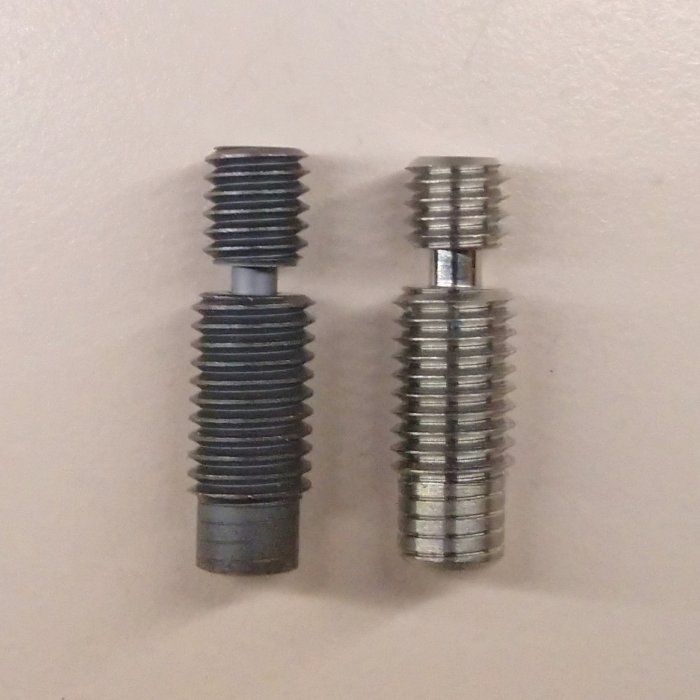
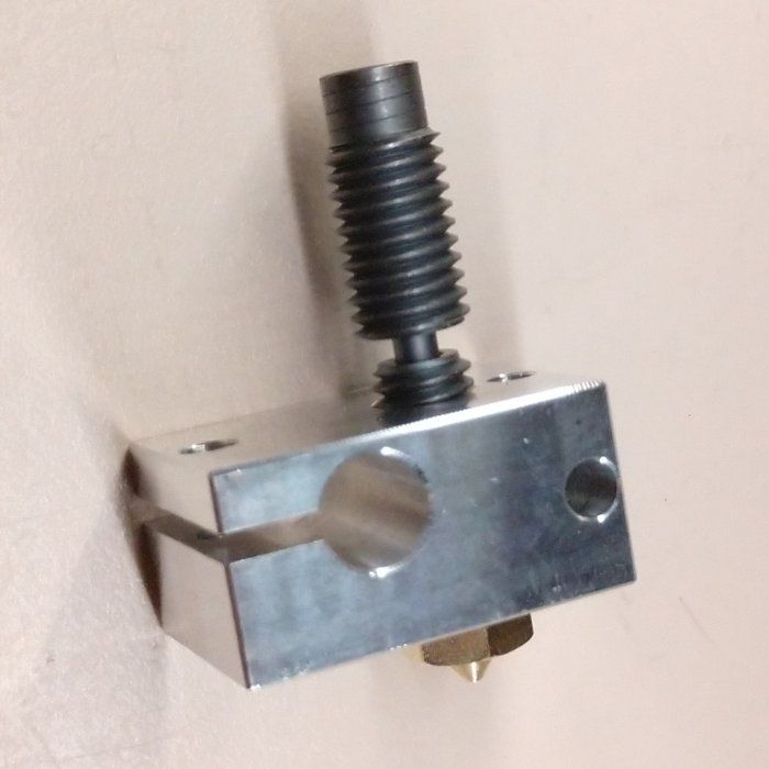
    Has anyone tried using the RepRap version of the Slice Copperhead heat break in an E3Dv6? Mine just came. Apparently the Copperhead heater block has a longer threaded section than E3D. It sticks out a bit, but I'm going to to grease it with boron nitride and try it anyway.
    side-by-side.jpeg

    installed.jpeg

    posted in 3D Printing General Chat
    undefined
    owlfab
    6 Aug 2020, 16:26
  • RE: What limits the homing feed rate?

    Thanks guys. I am running 3.1.1 now with 16x microstepping (with interpolation) and it is working fine. I noticed that this version can't handle full speed on X and Y at 256x microstepping like version 2.02 did, but it sounds like 16x is kind of the norm.

    In retrospect, that was really old firmware. I just didn't think to check, since the board was a relatively new purchase.

    posted in Tuning and tweaking
    undefined
    owlfab
    2 Aug 2020, 20:28
  • RE: What limits the homing feed rate?

    Maybe I answered my own question. I'm going to upgrade the FW to 3.0 and see what happens.

    posted in Tuning and tweaking
    undefined
    owlfab
    2 Aug 2020, 18:54
  • RE: What limits the homing feed rate?

    The behavior occurs if I run the macro after a reset, home Z, and execute a G0 Z10 to provide room for travel. Using H1 vs. S1 doesn't make a difference.

    My firmware version is 2.02(RTOS) (2018-12-24b1)

    Config file:

    ; General preferences
    G90                                     ; send absolute coordinates...
    M83                                     ; ...but relative extruder moves
    M550 P"OwlFab1000"                      ; set printer name


    M667 S1                                 ; select CoreXY mode
    
    ; Network
    M552 S1                                 ; enable network
    M586 P0 S1                              ; enable HTTP
    M586 P1 S0                              ; disable FTP
    M586 P2 S0                              ; disable Telnet
    
    ; Remove these for DHCP
    M552 S0 
    M552 S1 P192.168.0.10
    
    ; Drives
    M569 P0 S1                          
    M569 P1 S0                        
    M569 P2 S1                             
    M569 P3 S1                             
    M569 P4 S1                              
    M584 X0 Y1 Z2:4 E3                         ; set drive mapping
    M350 X256 Y256 Z256 E16 I0                 ; configure microstepping without interpolation
    M92 X2560.00 Y2560.00 Z25600.00 E268.63    ; set steps per mm M203 X9000.00 Y9000.00 Z1000.00 E3000.00   ; max speed (mm/min)
    M566 X800.00 Y800.00 Z150.00 E1500.00      ; jerk (mm/min)
    M203 X9000.00 Y9000.00 Z1000.00 E3000.00   ; max speed (mm/min)
    M201 X1000.00 Y1000.00 Z150.00 E1800.00    ; set accelerations (mm/s^2)
    M906 X800 Y800 Z1200 E1200 I30             ; set motor currents (mA) and motor idle factor in per cent
    ;M906 X500 Y500 Z600 E600 I30              ; stealth mode
    M84 S10                                    ; Set idle timeout
    
    ; Axis Limits
    M208 X0 Y0 Z0 S1                        ; set axis minima
    M208 X250 Y195 Z268 S0                  ; set axis maxima
    
    ; Endstops
    M574 X1 Y1 Z2 S1                        ; set active high endstops
    
    ; Z-Probe
    M558 P0 H5 F120 T6000                   ; disable Z probe but set dive height, probe speed and travel speed
    M557 X15:215 Y15:195 S20                ; define mesh grid
    
    ; Heaters
    M305 P0 T100000 B4138 R4700             ; set thermistor + ADC parameters for heater 0
    M143 H0 S120                            ; set temperature limit for heater 0 to 120C
    M305 P1 T100000 B4138 R4700             ; set thermistor + ADC parameters for heater 1
    M143 H1 S280                            ; set temperature limit for heater 1 to 280C
    
    ; Fans
    M106 P0 S0 I0 F500 H-1                  ; set fan 0 value, PWM signal inversion and frequency. Thermostatic control is turned off
    M106 P1 S1 I0 F500 H1 T45               ; set fan 1 value, PWM signal inversion and frequency. Thermostatic control is turned on
    
    ; Tools
    M563 P0 D0 H1 F0                        ; define tool 0
    G10 P0 X0 Y0 Z0                         ; set tool 0 axis offsets
    G10 P0 R0 S0                            ; set initial tool 0 active and standby temperatures to 0C
    
    
    T0                                      ; select first tool 
    M203 X9000.00 Y9000.00 Z1000.00 E3000.00   ; max speed (mm/min)
    ; Stall detection
    ; M915 X Y S5 R2 
    
    ; Pressure advance
    M572 D0 S1.
    

    My Z home macro is:

    ; homez.g
    ; called to home the Z axis
    ;
    ; generated by RepRapFirmware Configuration Tool v2.1.8 on Tue Mar 31 2020 14:27:47 GMT-0700 (Pacific Daylight Time)
    G91              ; relative positioning
    ;G1 S2 Z5 F600   ; lift Z relative to current position
    G0 S1 Z295 F800  ; move Z up until the endstop is triggered
    G92 Z268         ; set Z position to axis maximum 
    G1 S2 Z-5 F6000  
    G90              ; absolute positioning
    
    posted in Tuning and tweaking
    undefined
    owlfab
    2 Aug 2020, 18:20
  • What limits the homing feed rate?

    Something is limiting my Z homing feed rate, and I can't figure out what. Is there anything other then the G0/G1 F argument or G203 that could do this? I made a macro that demonstrates my issue:

    G91              
    G0 S1 Z100 F1000  ; This seems to run at about 500 mm/min
    G90 
    
    G0 Z0 F1000  
    
    G91              
    G0 Z100 F1000     ; This runs at full speed      
    G90 
    
    G0 Z0 F1000
    
    posted in Tuning and tweaking
    undefined
    owlfab
    2 Aug 2020, 17:15
  • RE: 600mm bowden setup pressure advance calibration

    @Phaedrux
    Thanks for the tip. I will give it a try.

    @Slzer
    It does seems weird that your towers look the same. When I was printing the hollow towers, the main thing I was watching was the corner where the layer transition happened. On my printer, I was getting a blob there without using advance. Turning it up too high resulted in a gap. If it wasn't for that blob, I probably wouldn't have even bothered.

    posted in Tuning and tweaking
    undefined
    owlfab
    28 Jul 2020, 15:57
  • RE: 600mm bowden setup pressure advance calibration

    One thing I appreciate about the Duet is that you can change most of the motion settings on the fly. If you paste it into the web interface while printing, you can observe the effects immediately without having to start a new print. Then when you have something that works, you can edit config.

    I just replaced all of my steppers. Things are still kind of in flux, but the benchy printing right now looks good so far. Here are the relevant lines from my config.g. As you can see, I went down to S1.

    M584 X0 Y1 Z2:4 E3                         ; set drive mapping
    M350 X256 Y256 Z256 E256 I0                ; configure microstepping without interpolation
    M92 X2560.00 Y2560.00 Z25600.00 E4298      ; set steps per mm 
    M566 X1000.00 Y1000.00 Z500.00 E1000.00    ; jerk (mm/min)
    M203 X18000.00 Y18000.00 Z1000.00 E3000.00 ; max speed (mm/min) 
    M201 X2000.00 Y2000.00 Z300.00 E1200.00    ; accelerations (mm/s^2)
    M906 X800 Y800 Z1200 E1200 I30             ; set motor currents (mA) and motor idle factor in per cent
    M84 S10                                    ; Set idle timeout
    
    ; Pressure advance
    M572 D0 S1
    

    Edit: I should say that my extruder max speed probably needs to be reduced, since I'm seeing some missed steps.
    posted in Tuning and tweaking
    undefined
    owlfab
    28 Jul 2020, 03:01
  • RE: 600mm bowden setup pressure advance calibration

    @Slzer said in 600mm bowden setup pressure advance calibration:

    Have i done something wrong here?

    That was pretty much my feeling when I set up pressure advance, and I'm still not completely convinced. FWIW I have a similar length bowden (can't measure it because I'm at work). I ended up converging on S1.4 just by printing some square towers and watching the corners. I'm replacing the stepper though, so that could change soon. For background, my extruder is non-geared, 1.75mm, and currently uses a 1.8 degree stepper that is barely strong enough.

    I had the same observation that the E stepper kind of goes crazy on small areas. High S values can be demanding. I found that it is very important to dial in E axis current/speed/acceleration/jerk properly. If the stepper can't keep up, the E axis can become the limiting factor for overall print speed, or it can miss steps.

    posted in Tuning and tweaking
    undefined
    owlfab
    24 Jul 2020, 20:23
  • RE: High Temperature printing

    Really interesting thread here.

    How about using lead screws for high temp chambers? It seems like you could adapt the Ultimaker style x/y mechanism to use lead screws instead of rods and belts, and thus keep everything sensitive outside the chamber. It could be made cheap and simple, except that you would probably need to make some custom metal parts.

    posted in General Discussion
    undefined
    owlfab
    23 Jul 2020, 15:56
  • RE: 5V regulator failure (U3)

    @bearer said in 5V regulator failure (U3):

    Its worth taking into account that the board is 2oz copper (assuming genuine duet), the failed chip is in one of the most densly populated areas with heavy ground planes in 4 layers.

    Yeah, that actually sounds really unpleasant. Removing L3 and L2 would probably be easier, but it is still tight.

    posted in Duet Hardware and wiring
    undefined
    owlfab
    22 Jul 2020, 22:26
  • RE: 5V regulator failure (U3)

    From experience, trying to find shorts on power rails can be a pain, so good luck!

    posted in Duet Hardware and wiring
    undefined
    owlfab
    22 Jul 2020, 19:51
  • RE: 5V regulator failure (U3)

    I guess I was confused because it sounded like you had it up and running on external 5V. You are right, if U3 is slag, it could be pulling down the 5V rail.

    If you are not going to replace U3, you should isolate if from the rails. Looking at the actual board and the schematic again, I think the best way would be to remove L3 (not L1 like I originally suggested). While you are at it, remove L2 to isolate it from the input rail. Then check the 5V rail again.

    On the other hand, if you want to try to replace U3 and you suspect D2, you would probably do best to desolder it and check it out of circuit. Or you could desolder U3 since you know it is bad, and then check D2 in-circuit.

    posted in Duet Hardware and wiring
    undefined
    owlfab
    22 Jul 2020, 19:49
  • RE: 5V regulator failure (U3)

    Personally I would try to replace U3, but I have a hot air station. If you don't have experience with QFNs, it is going to be tricky.

    Using an external 5V source is an interesting idea. The one possible limitation I see is that you will be limited to 1A instead of 2A on the +5 rail, due to D14 (note on the schematic). Also, if you can't remove U3, you might want to remove L1 and L2 so you don't end up powering or backfeeding the damaged U3. On the other hand, if you already have it running it might not matter.

    duet2_snip.png

    posted in Duet Hardware and wiring
    undefined
    owlfab
    22 Jul 2020, 17:00
  • RE: Fan8 output weird stuff

    I'm assuming you have the jumper set to 5V?

    If you are measuring 4.95V across the pins with the fan turned off, that seems wrong.

    However, neither of the fan pins is actually tied to GND. One of the fan pins is always going to show 5V/12V/VIN relative to GND (selectable by jumber). The other one is pulled closer to GND the higher the fan speed is set.

    All that is to say, your measurements almost make sense if you are measuring the low-side pin relative to actual GND. Maybe you could just attach a fan and see if it works?

    posted in Duet Hardware and wiring
    undefined
    owlfab
    22 Jul 2020, 16:08
  • RE: Fan8 output weird stuff

    How exactly are you measuring the voltage? Across the two connector pins, or relative to ground? Is the fan connected?

    posted in Duet Hardware and wiring
    undefined
    owlfab
    21 Jul 2020, 21:48
  • Help choosing the quieter motor

    I'm upgrading my the x/y and e steppers on my homebrew corexy, and I'm looking for some advice. I've narrowed it down to:
    LDO-42STH60-2004MAC
    MT-1704HSM168RE aka E3D High Torque Axis Motor

    I am sure either one would do the job, but I want to keep the printer as quiet as reasonably possible. It seems like the LDO is going to be louder, since it is acting against a higher rotor inertia. Does that seem like a reasonable assumption?

    For background, I'm running about 15V on a Duet2. The extruder end is non-geared. My pressure advance is set pretty high, which means there are a lot of fast extruder movements.

    posted in Duet Hardware and wiring
    undefined
    owlfab
    19 Jul 2020, 00:14
Unless otherwise noted, all forum content is licensed under CC-BY-SA