@t3p3tony thanks, now it only has to become available at a European reseller 

Best posts made by pixelpieper
-
RE: Announcement: Duet 3 Toolboard revision v1.1posted in Duet Hardware and wiring
-
RE: Configuring 12864 LCD on Maestro?posted in Duet Hardware and wiring
Hi, First post here, I thought that may help you guys out a bit...

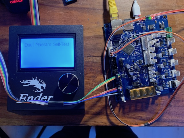
If anyone else wants a simple clean way to create a single ribbon cable which does not involve dupont connectors: You can easily crimp yourself a cable, just get yourself some connectors (like this one, no affiliation with sparkfun). You can either reuse the existing cable or, simpler, get some rainbow ribbon cable which allows you to follow this color scheme:

All connectors as seen from the top, i.e. the order in which the pins are on the connectorsCrimp the cable on the LCD side with all wires, if using a rainbow ribbon align the marker (small triangle) with the brown wire so that the colors match up the illustration. Carefully cut the ribbon after two wires, in the center and finally just before the outer two wires. For the EXP1 connector align the first two and last two wires identical to their position on the LCD side. Take the second three wire pair and align it flipped over with the first wires. The top "bridge" of the connector has some indentations which helps with the proper alignment. You should have three remaining wires, these go into the exp2 connector, again flipped over. make sure to skip the first two positions and you should be fine.
Happy crimping!
--Edit--
Configuration when using this wiring to have the wheel inputs properly working:
M918 P1 E-4 -
RE: Non Duet Hardware with RRF ?posted in Duet Hardware and wiring
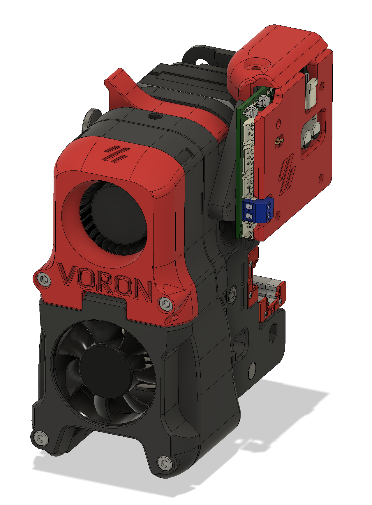
@Herve_Smith I have this experimental one which mounts the 1LC in the flap, leaves just enough room to allow for the chain and exposes the two buttons which I have programmed to extrude/retract


-
Neopixel support on 1LC?posted in Firmware wishlist
Would it be possible to add neopixel support to the 1LC firmware on IO0? I am aware that I will likely need to add a buffer as a level shifter and that I won’t be able to drive more than maybe three or four pixels, but it would simplify adding lights to the toolhead.
-
RE: RESOLVED. WAS: thermistor bug in 3.2beta 2 on Duet Maestroposted in Beta Firmware
Sorry for the confusion, it seems I might have had a wiring or crimp issue which by chance developed in parallel to playing with the beta. Having it seamingly disappear while downgrading did not help either...

I will replace all my hotend thermistors with PT1000, a wire fault resulting in to low a temperature reading is to dangerous in my opinion, so the upgraded sensors will give me some peace of mind.
-
RE: Heater Monitor Setup (M143)posted in Duet Hardware and wiring
Nevermind, Fixed it - Problem was the order of my commands, I now moved the M140 and M307 to before the M143 definition:
;; thermal ------------------------------------------------- ; Sensors -------------------------------------------------- M308 S0 P"bedtemp" Y"thermistor" T100000 B3950 A"Bedmat"; configure sensor 0 as thermistor on pin temp0 M308 S1 P"e0temp" Y"pt1000" A"Hotend" ; configure sensor 1 as thermistor M308 S2 P"ctemp" Y"thermistor" T100000 B3950 A"Chamber" ;Chamber fan M308 S3 Y"mcu-temp" A"Board" M308 S4 P"e1temp" Y"thermistor" T100000 B3950 A"Bedplate" ; Heaters -------------------------------------------------- ;Bed M950 H0 C"bedheat" T4 ; create bed heater output on out0 and map it to sensor 4 M950 H1 C"e0heat" T1 ; create nozzle heater output on e0heat and map it to sensor 1 M140 H0 ;PID Settings M307 H0 A301.0 C845.3 D1.4 S1.00 V23.6 B0 M307 H1 A482.6 C291.7 D5.5 S1.00 V23.6 B0 ;V6 ; Monitors & Limits M143 H0 P1 T0 A2 S110 C0 ; Regulate (A2) bed heater (H0) to have pad sensor (T0) below 110°C. Use Heater monitor 1 for it M143 H0 P2 T0 A0 S120 C0 ; Fault (A0) bed heater (H0) if pad sensor (T0) exceeds 120°C. Use Heater monitor 2 for it M143 H0 P0 S110 ; Set bed heater max temperature to 120°C, use implict monitor 0 which is implicitly configured for heater fault M143 H1 S400 ; set temperature limit for heater 1 to 275C -
RE: Comparing klipper and RRF input shaper data collectionposted in Beta Firmware
One thing I should have mentioned: these are two fundamentally different approaches to achieve the same thing.
-
Klipper does a sweep where they try to stimulate the system at different frequencies. The ideal input signal for this measurement is a perfect sinusoidal not containing other frequency components, the unknown factor here is how well the sinusoid is approximated by the acceleration/deceleration curves.
-
RRF measures an impulse response based on a fast movement. The ideal input signal here is a very fast acceleration which equally contains all the frequency components of interest. The question here is how well that is achieved.
Both should come to a similar conclusion.
-
-
Duet 2 Maestro and FYSETC Mini12864posted in Duet Hardware and wiring
After creating my third Maestro Mini12864 wiring loom I thought it might be time to create a Pinout for others to reuse...

This is for the Mini12864 in Version 1.2 without RGB - tested with RC1 of Version 3.2


-
RE: Comparing klipper and RRF input shaper data collectionposted in Beta Firmware
@gloomyandy said in Comparing klipper and RRF input shaper data collection:
Folks, please be aware that if you use this script with a the current version of RRF (V3.4beta6) or a previous version then you will only be able to collect a maximum of 64K samples (so approx 50 seconds of data, with a sample rate of approx 1320), given that the gcode generated by this script runs for longer than this you may not have good coverage of higher frequencies (as they come later in the test sequence). In my tests I am using a modified (and currently unreleased) version of RRF. Later versions of RRF may make it possible to collect more samples but that is up to @dc42. You may be able to experiment with a capturing the full range by setting your accelerometer to use a lower sampling rate, but this is not something I have tried.
It's been a while since I have had my signal processing classes, so feel free to correct any mistakes, but based on theory each acceleration and deceleration contain all the frequency components. (Ok, this is only true for an infinite acceleration / deceleration, but a fast move should be close enough to capture the frequency range of interest.)
The Klipper approach wiggling the head about is mainly giving you more data and hence a higher resolution of the spectrum which is why you see more noise in the plot.
Btw,. reducing the sampling rate "to capture the full range" will have the opposite effect: the Nyquist–Shannon sampling theorem applies and reducing the sampling rate reduces the maximum frequency that can be sampled which is f_sampling/2.
-
RE: Announcement: Duet 3 Toolboard revision v1.1posted in Duet Hardware and wiring
Any chance we can get a STEP for the new Version? I am trying to do a mount for a tight space, would be useful to have a complete 3d model. Guesstimates from the 1.0-Step wont work well as the connectors changed and the new board is slightly larger...
-
RE: 12864 display (ST7920) on Duet 3 Mini5+posted in Duet Hardware and wiring
@diy-o-sphere I would change it by more - maybe half the default. Otherwise this might break again with small environmental changes in temperature or humidity or just over time...
-
RE: Announcement: Duet 3 Toolboard revision v1.1posted in Duet Hardware and wiring
@dc42 Totally understandable. Nevertheless, I would be happy to pay 5-10 euro more for V1.1 to finance someone else getting the same amount off on a V1.0...
-
RE: Duet 2 Pro 4 Uposted in Hardware wishlist
@bot Modern drivers with Stealthchop, more Memory, Raspberry-Pi interface, Neopixel-Support
-
RE: Duet 3 Mini 5+ : Initial announcementposted in General Discussion
@dc42 Very happy to see the shift to allow for using the Mini 12864 display, will it support the Neopixel backlight variants without a custom cable? Support of this display was the last bit missing for full support of the Voron 2.4!
I would be happy to buy a prototype of this board + the three stepper extension for beta testing so that a manual & example configuration for the Voron 2.4 can be ready as soon as it hits the market
-
RE: RESOLVED. WAS: thermistor bug in 3.2beta 2 on Duet Maestroposted in Beta Firmware
Unlikely, I swapped the whole hotend and I have seen the issues with both now. Also, the Molex MicroFit connectors are very reliable. And in the drag chain I have Heluflon Teflon coated cable which is well suited for this application... - will anyway replace the drag chain cable tomorrow and twist the thermistor wire.
-
RE: Swapping Ender 3 Control Board with Duet 2 Maestroposted in Duet Hardware and wiring
Been there, done that. I replaced the case fan and the hotend cooling fan with noctua NF-A4x10 5V - the maestro board allows you to jumper the fans to 5V. This significantly dropped the machine noise. No need to do so however from the start, the fans used by Creality are actually 24V models.
For the wiring of the display: this is the relevant thread where I posted an instruction to create an adapter cable
You should get new connectors with your maestro board, get yourself a proper crimping tool and just replace the JST plugs with the Würth ones - a bit annoying, but it is literally a one to one connection for everything but the end stops.
-
RE: Damaged mosfets on Duex?posted in General Discussion
@educatingsavvas for E3 and E4 it’s completely normal that one of the Pins is always at VIN - the MOSFETs switch the ground side.
-
[Bug / Feature Request]: negative temperatures in chartposted in Duet Web Control wishlist
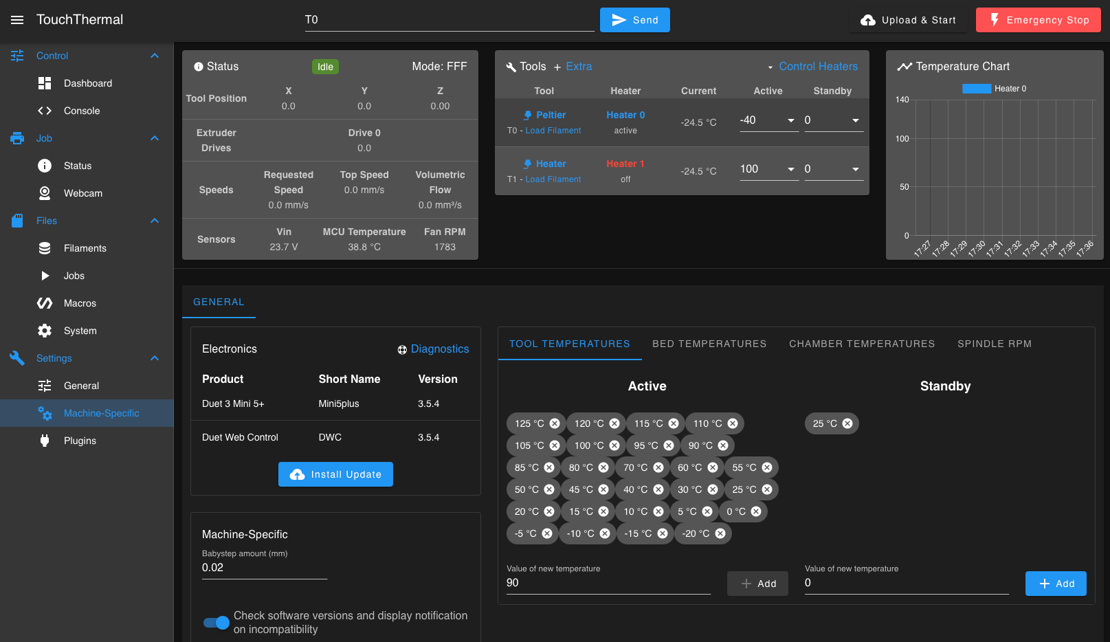
I am using a Duet board as a temperature controller for a measurement setup, using a peltier element for subzero temperatures. Unfortunately the temperature chart in DWC doesn't scale down to negative temperatures right now:

My proposal would be to extend the lowest temperature down to either
min(0, min(active_tooltemp_list),min(active_bedtemp_list),min(active_chambertemp_list))or
min(0, active_tool_temperature,active_bed_temperature, active_chamber_tamperature)This keeps the behavior as is for normal users while extending the chart down if required.
-
RE: Duet 2 Maestro and FYSETC Mini12864posted in Duet Hardware and wiring
@bearer said in Duet 2 Maestro and FYSETC Mini12864:
Could you just add which of the two chipsets that display uses? ST7920 or ST7565 iirc.
The Mini12864 uses the ST7565. Displays with the ST7920 such as the reprep discount one are natively supported without the need of a dedicated wiring loom.
Configuration needed:
; Enable LCD M918 P2 E-4 -
RE: What would you build if you were starting again now?posted in General Discussion
@diy-o-sphere I have an inductive Superpinda on my V2 connected to the 1LC, works beautifully.
