Duet3D Logo Duet3D
    • Tags
    • Documentation
    • Order
    • Register
    • Login
    1. Home
    2. Red Sand Robot
    3. Posts
    • Profile
    • Following 0
    • Followers 1
    • Topics 25
    • Posts 113
    • Best 14
    • Controversial 0
    • Groups 0

    Posts made by Red Sand Robot

    • RE: Autotramming minor issue (Cartesian machine)

      @Phaedrux @engikeneer

      ;Z-Probe
      M307 H3 A-1 C-1 D-1	             ; Enables usage of expansion header pins for BL Touch 
      M558 P9 H3 F150 T5500 R0.2 A15 S0.01 ; BLTouch, set dive height, probe speed, travel speed, 
      				     ;number of times to probe a single point, tolerance when probing multiple times
      G31 X-16 Y-42 Z1.49 P25              ; X,Y offset, Z trigger height, P is signal threshold
      M557 X-74:74 Y-42:42 S37:21          ; Define mesh grid
      M376 H2.2			     ; Define mesh taper height (2.2mm), removes compensation above this height
      
      ; Axis Limits
      M584 X0 Y1 Z4:2 E3 	       ; two Z motors connected to driver outputs Z and E1
      M671 X-158:152 Y0:0            ; leadscrews at left (connected to Z) and right (connected to E1) of X axis
      M208 X-102 Y-106 Z-0.05 S1     ; Set axis minima and low homing switch position
      M208 X100 Y100 Z200 S0         ; Set axis maxima
      

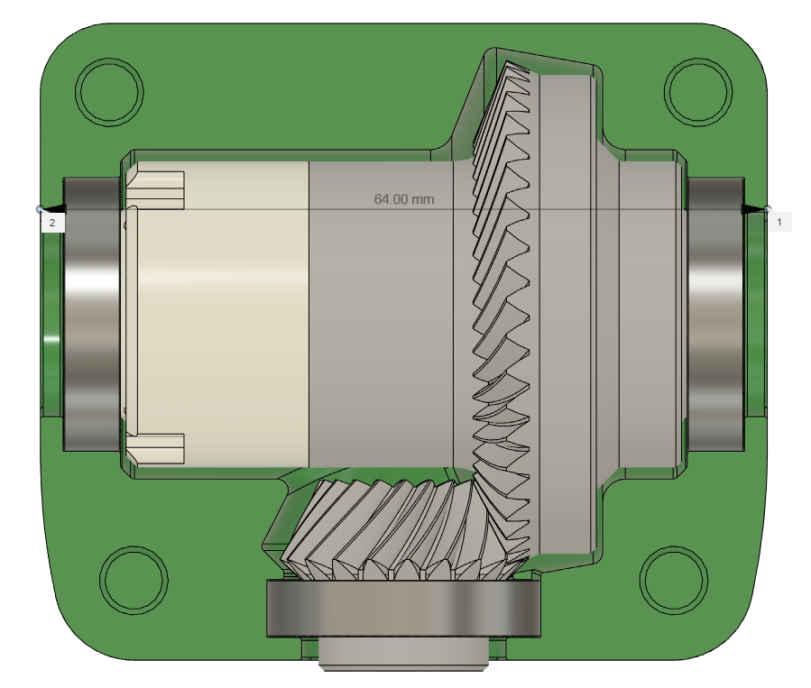
      Lead screw positions are relative to 0,0, and by buildplate is slightly off center. Possibly this is the main issue?

      ; bed.g
      ; called to perform automatic bed compensation via G32
      ;
      M561 ; clear any bed transform
      G30 P0 X-100 Y0 Z-99999    ; probe near a leadscrew, half way along Y axis
      G30 P1 X84 Y0 Z-99999 S2 ; probe near a leadscrew and calibrate 2 motors
      
      ; --> Start G-code <--
      G21     ;metric values
      G90     ;absolute positioning
      M107    ;start with the fan off
      G29 S2  ;clears existing bed heightmap
      G28     ;home all 
      G32     ;motorized gantry plane correction
      G32     ;
      G32     ;repeated 3 times 
      G29     ;mesh bed compensation 
      G1 Z20 F6000 ;move the nozzle to Z=20mm
      G1 F100 E5 ;extrude 5mm of filament
      G92 E0  ;zero the extruded length
      
      posted in Tuning and tweaking
      Red Sand Robotundefined
      Red Sand Robot
    • RE: Autotramming minor issue (Cartesian machine)

      @engikeneer

      The heightmap is cleared before every print as a start, and mesh leveling only happens after homing and tramming. However, I am not resetting my z-axis zero after every tramming command. I can see now how that would be an issue. Probe offsets should be optimal, as well as leadscrew positions.

      First thing I will try will be to insert a G28 Z command after every tramming attempt and see if that solves the issue.

      It is strange, though, as I do not remember this being an issue when I first switched to independent dual z-axis stepper control.

      If that does not work I will post relevant files to see if someone can spot an error in what I have configured.

      posted in Tuning and tweaking
      Red Sand Robotundefined
      Red Sand Robot
    • Autotramming minor issue (Cartesian machine)

      Hello all,

      Wondering if anyone has any suggestions for me: currently my pre-print routine consists of zeroing all axes, running an autotramming of the gantry 3x times, and then running a mesh bed compensation.

      What I have noticed is that the right side of my build plate is always closer to the nozzle, and the left side farther away at the beginning of the print. I am using a BLtouch, multiple probes per point. I had assumed probing multiple times per point, along with autotramming three times, would ensure that my gantry is planar to my build plate, but it seems this is not the case.

      Does this seem like a mechanical issue, or possible due to the multiple probings/accuracy issues with the BLtouch?

      posted in Tuning and tweaking bed leveling auto tramming cartesian
      Red Sand Robotundefined
      Red Sand Robot
    • RE: Fusion 360 FFF Slicer: G2/G3 Generation Now in Preview

      It is a real shame that Autodesk's personal use policies have detracted from the addition of a barebones 'arc fit' function for their slicer in F360. I just thought it was a neat addition, and implemented very quick compared to other features, but it got overshadowed immediately by removal of features. I feel the better direction would have been to stagger some features behind cheaper paywalls (i.e. $10 USD/month for 5-axis CAM, $10USD/month for simulation, etc) vs locking everything behind a commercial subscription when it is likely a majority of their current user base are not commercial.

      (edit: spelling)

      posted in 3D Printing General Chat
      Red Sand Robotundefined
      Red Sand Robot
    • RE: Fusion 360 FFF Slicer: G2/G3 Generation Now in Preview

      @bot said in Fusion 360 FFF Slicer: G2/G3 Generation Now in Preview:

      They already removed importing of "professional" cad formats last year or early this year. So, no more STEP, IGES or SLDPRT/ASM for free users.

      Actually, STEP/IGES are still allowed.

      https://www.autodesk.com/products/fusion-360/pricing?_ga=2.5665779.1578081928.1600206184-2086964182.1571363456

      Interestingly enough, apparently you can still export to an Inventor part/assembly file, but not import! Very odd.

      posted in 3D Printing General Chat
      Red Sand Robotundefined
      Red Sand Robot
    • RE: Fusion 360 FFF Slicer: G2/G3 Generation Now in Preview

      @bearer Screenshot 2020-09-16 105658.png

      There is no mention of changing import options, so you could conceivably still import .step or.iges files. Also, Fusion project files can still be exported, so a workaround for storage of only 10 projects could be exporting the project and archiving it on a local storage solution and then re-uploading it when needed. Not sure what archived/active means, I don't see the difference between continually 'archiving' and then making a document 'active' unless the process is annoying enough to make it an unwanted step in the modeling workflow.

      I think these changes were brought about from people abusing the personal license for commercial uses. Even then, a yearly subscription for Fusion 360 is only around USD $500, which is a lot cheaper than the major CAD/CAM players (Solidworks, Inventor, Solidedge, etc). (Yes, cheaper is relative, five hundred dollars isn't an insignificant amount of money)

      posted in 3D Printing General Chat
      Red Sand Robotundefined
      Red Sand Robot
    • RE: Fusion 360 FFF Slicer: G2/G3 Generation Now in Preview

      @littlehobbyshop
      I think I got it to work. There are two lines of sneaky variables that I missed the first time I copied the blocks over, had to do with the var iOutput = createReferenceVariable({prefix:"I", force:true}, xyzFormat); // circular output1 and
      var jOutput = createReferenceVariable({prefix:"J", force:true}, xyzFormat); // circular output variables being missing in my initial modification to your post.

      For whatever reason, it is not working with a custom print profile, but I changed over to the stock "ABS 1.75mm" print profile and it was generating G3 commands for a flat donut shape.

      unofficial rrf machine with arc smoothing.cps

      1032.gcode

      I think modifying the stock print profiles in certain ways may affect the curve fitting.

      @bot I agree, fitting after the fact is not optimal but it is a step in the right direction. Probably leverage existing code from their CAM workspace to make it work.

      posted in 3D Printing General Chat
      Red Sand Robotundefined
      Red Sand Robot
    • RE: Fusion 360 FFF Slicer: G2/G3 Generation Now in Preview

      @Phaedrux @arhi Scratch that, those additions aren't quite enough. Using the Prusa post however does generate G3 moves! It cut a roughly 1100kb file to around 500kb. Still trying to get the 'rrf' post to function correctly

      posted in 3D Printing General Chat
      Red Sand Robotundefined
      Red Sand Robot
    • RE: Fusion 360 FFF Slicer: G2/G3 Generation Now in Preview

      @Phaedrux @arhi @littlehobbyshop

      Look for this line in the RRF post processor (or your own custom one):

      capabilities = CAPABILITY_ADDITIVE;
      highFeedrate = (unit == MM) ? 6000 : 236;
      

      Beneath that, copy and paste this block:

      // used for arc support or linearization
      tolerance = spatial(0.002, MM); // may be set higher i.e 0.02?
      minimumChordLength = spatial(0.25, MM);
      minimumCircularRadius = spatial(0.4, MM);
      maximumCircularRadius = spatial(1000, MM);
      minimumCircularSweep = toRad(0.01);
      maximumCircularSweep = toRad(180);
      allowHelicalMoves = false; // disable helical support
      allowSpiralMoves = false; // disable spiral support
      allowedCircularPlanes = 1 << PLANE_XY; // allow XY circular motion
      

      And farther below that, in the functions section, paste this below the onLinearExtrude function.

      function onCircularExtrude(_clockwise, _cx, _cy, _cz, _x, _y, _z, _f, _e) {
        var x = xOutput.format(_x);
        var y = yOutput.format(_y);
        var z = zOutput.format(_z);
        var f = feedOutput.format(_f);
        var e = eOutput.format(_e);
        var start = getCurrentPosition();
        var i = iOutput.format(_cx - start.x, 0); // arc center relative to start point
        var j = jOutput.format(_cy - start.y, 0);
        
        switch (getCircularPlane()) {
        case PLANE_XY:
          writeBlock(gMotionModal.format(_clockwise ? 2 : 3), x, y, i, j, f, e);
          break;
        default:
          linearize(tolerance);
        }
      }
      

      Those are the only differences I can currently see between the generic FFF post processor and the Prusa post processor.

      Note: I still have not tested this yet. Also, it may be worth looking in to the variables defining circular moves, i.e. minimumChordLength and seeing what those may change.

      posted in 3D Printing General Chat
      Red Sand Robotundefined
      Red Sand Robot
    • RE: Fusion 360 FFF Slicer: G2/G3 Generation Now in Preview

      @Phaedrux Not quite sure, as I haven't tried to use it yet (was planning on later today). Hoping it's easy enough to reconfigure the Prusa post-processor for a Duet compatible output while retaining arc support.

      posted in 3D Printing General Chat
      Red Sand Robotundefined
      Red Sand Robot
    • Fusion 360 FFF Slicer: G2/G3 Generation Now in Preview

      As the title says, the slicer in Fusion 360, while still a little rough, now has the ability to apply 'Arc Fit Optimization' for models. Screenshot_20200914-192846.jpg
      Super stoked about this development, and I am actually surprised they got around to implementing it this quickly given how slow they have been with other needed updates for other environments (namely adding weld symbols in the drawing environment)

      posted in 3D Printing General Chat arc moves fusion360 slicer
      Red Sand Robotundefined
      Red Sand Robot
    • RE: Неправильная работа оси Z.

      @Phaedrux Those are in the first post, along with a sample g-code that the issue was being seen with.

      posted in General Discussion
      Red Sand Robotundefined
      Red Sand Robot
    • RE: Неправильная работа оси Z.

      @Maks
      После того, как ось z была перемещена в исходное положение, можете ли вы переместить ось z, если печать не выполняется?

      Cura - единственное программное обеспечение, предоставляющее вам файлы с g-кодом, у которых есть эта проблема, или вы пробовали Prusaslicer, Slic3r или другие?

      (Используется Google Translate)

      posted in General Discussion
      Red Sand Robotundefined
      Red Sand Robot
    • Fusion 360 working on adding G2/G3 Support

      I was reading the current roadmap blog post for Fusion 360, and it seems they are working on implementing G2/G3 support. (Also adding support for resin printers but I think the vast majority of Duets are used with filament printers.

      Fused Filament Fabrication (FFF) Improvements

      After the March 2020 update, Fusion 360 became a slicer for FFF printers overnight. As awesome as this release was for FFF, it had a couple of kinks. The team has, since then, been working hard at improving the usability and fixing any and all reported issues. You can expect to see a continued investment in this area. We are adding new printers, new post files and new functionality update after update. Some of the key projects that excites us are around G2/G3 support, new infill types, dual extrusion improvements and overall increased performance around toolpath generation.

      Stereolithography (SLA) / Digital light projector (DLP) 3D Printing

      FFF and metal powder bed fusion printers are great and all, but 3D printer processes are very diverse, and we want Fusion 360 to support all kinds of printing techniques. We are working on enabling SLA and DLP print preparation such as integrating printer workspaces, SLA/DLP specific support generation methods, packing parts within the platform, and slicing models for these types of printers. We can’t wait to see what you design and print using Fusion 360.

      https://www.autodesk.com/products/fusion-360/blog/fusion-360-roadmap-update-2020/#Additive

      (They do have a section on their forum for adding feedback for the FFF slicer part of Fusion 360, so I would think a fair amount of Duet users could give them some good, critical feedback on the quality of toolpath generation, needed features, issues, etc.)

      posted in General Discussion
      Red Sand Robotundefined
      Red Sand Robot
    • RE: Cura Script to Automatically Probe Only Printed Area

      @zapta Would --meshable=-100:100,-100:100 go after the output path specification in PrusaSlicer? I just manually changed the default in the script.

      parser.add_argument('--meshable',
                          default="-100:100,-100:100",
                          help='Bed meshable area x1:x2,y1:y2')
      

      Here is the .gcode file. I have my 0,0 point in the center of the build plate. I know that you previously added support for negative positional values so I don't think that would be the issue
      flex_tube_support2.gcode

      posted in General Discussion
      Red Sand Robotundefined
      Red Sand Robot
    • RE: Cura Script to Automatically Probe Only Printed Area

      @zapta Figured out that my main issue was that I never changed the meshable area parameters to match my machine. I guess I just assumed when it says "default" that the script would also parse that stuff from the slicer, but in hindsight the script doesn't function that way, it only looks at the .gcode file after it has been output by the slicer.

      Leaving output up as an example of what it looks like the user does not properly define the meshable area in regards to their machine. My machine has -100:100,-100:100 for a meshable area.

      C:\Users\Jack>C:\Users\Jack\AppData\Local\Programs\Python\Python38-32\python.exe C:\Users\Jack\Documents\3D-Printing\PrusaSlicerScript\duet3d_automesh.py C:\Users\Jack\Documents\3D-Printing\Stuff\flex_tube_support2.gcode
      MESHABLE area: 30.0:280.0,30.0:280.0
      Opening gcode file: C:\Users\Jack\Documents\3D-Printing\Stuff\flex_tube_support2.gcode
      Read 33095 lines
      Parsing state = ParsingState.WAITING_FOR_LAYER1
      ; Automesh: begin layer 0
      Parsing state = ParsingState.IN_LAYER1
      ; Automesh: begin layer 1
      Parsing state = ParsingState.LAYER1_DONE
      First layer print areas: -13:13,-48:48
      printArea: -13:13,-48:48
      Traceback (most recent call last):
        File "C:\Users\Jack\Documents\3D-Printing\PrusaSlicerScript\duet3d_automesh.py", line 371, in <module>
          main()
        File "C:\Users\Jack\Documents\3D-Printing\PrusaSlicerScript\duet3d_automesh.py", line 218, in main
          mesh_area.clip_to(MESHABLE_AREA)
        File "C:\Users\Jack\Documents\3D-Printing\PrusaSlicerScript\duet3d_automesh.py", line 165, in clip_to
          self.x_span.clip_to(other_rect.x_span)
        File "C:\Users\Jack\Documents\3D-Printing\PrusaSlicerScript\duet3d_automesh.py", line 126, in clip_to
          self.__check()
        File "C:\Users\Jack\Documents\3D-Printing\PrusaSlicerScript\duet3d_automesh.py", line 105, in __check
          fatal_error(f'Invalid range value: {self}')
        File "C:\Users\Jack\Documents\3D-Printing\PrusaSlicerScript\duet3d_automesh.py", line 83, in fatal_error
          raise Exception('Fatal error: ' + message)
      Exception: Fatal error: Invalid range value: 30.0:23
      
      posted in General Discussion
      Red Sand Robotundefined
      Red Sand Robot
    • RE: Cura Script to Automatically Probe Only Printed Area

      @zapta Yes, I work on windows. Haven't made the jump to attempt to learn Linux or associated stuff yet though I suppose I should if I ever want to use a RPI for anything useful.

      When I ran the script from the command prompt window, I received this output:

      C:\Users\Jack>AppData\Local\Programs\Python\Python38-32\python.exe "C:\Users\Jack\Documents\3D Printing\PrusaSlicerScript\duet3d_automesh.py"
      usage: duet3d_automesh.py [-h] [--meshable MESHABLE] [--margin MARGIN] [--spacing SPACING]
                                [--min_points {2,3,4,5,6,7,8,9,10,11,12,13,14,15,16,17,18,19,20,21,22,23,24,25,26,27,28,29,30,31,32,33,34,35,36,37,38,39,40,41,42,43,44,45,46,47,48,49}]
                                [--max_points {2,3,4,5,6,7,8,9,10,11,12,13,14,15,16,17,18,19,20,21,22,23,24,25,26,27,28,29,30,31,32,33,34,35,36,37,38,39,40,41,42,43,44,45,46,47,48,49}]
                                [--first_layer_start FIRST_LAYER_START] [--first_layer_end FIRST_LAYER_END]
                                file_path
      duet3d_automesh.py: error: the following arguments are required: file_path
      

      Does that look like it is functioning correctly? I'm guessing that the file_path argument is talking about the .gcode file, but if not that would indicate an error with how I'm calling the script from what I understand.

      posted in General Discussion
      Red Sand Robotundefined
      Red Sand Robot
    • RE: Cura Script to Automatically Probe Only Printed Area

      @zapta Command line? As in my computer or PrusaSlicer? Sorry, the programming side of things isn't my forte.

      posted in General Discussion
      Red Sand Robotundefined
      Red Sand Robot
    • RE: Cura Script to Automatically Probe Only Printed Area

      I'm also having an issue when getting the post processing script to run. I am getting this:

      Post-processing script C:\Users\Jack\AppData\Local\Programs\Python\Python38-32\python.exe "C:\Program Files\PrusaSlicer-2.2.0+win64-202003211145\PrusaSlicer-2.2.0+win64-202003211145\duet3d_automesh.py" on file C:\Users\Jack\Documents\3D Printing\Stuff\Flex Tube Support.gcode failed.
      Error code: 1
      

      Any ideas on what I may be doing wrong?
      This is my full start gcode script:

      M82 ;absolute extrusion mode
      G21 ;metric values
      G90 ;absolute positioning
      M82 ; set extruder to absolute mode
      M107 ;start with the fan off
      G29 S2; clears existing bed heightmap
      
      ; For automesh
      M557 TBD  ; parameters will be set automatically
      G28; home all
      
      G32; motorized gantry plane correction
      G32;
      G32; Repeated 3 times to ensure its correct
      
      G29  Mesh Bed compensation 
      
      G1 Z20 F6000 ;move the platform down 15mm
      G1 F100 E9 ;extrude 9mm of feed stock
      G92 E0 ;zero the extruded length
      
      
      posted in General Discussion
      Red Sand Robotundefined
      Red Sand Robot
    • RE: Vertical Hole Compression: Possible Solution

      @mrehorstdmd said in Vertical Hole Compression: Possible Solution:

      I printed a similar gearbox by splitting it into two pieces and printing both with the worm gear bearing slots facing up. Everything fit together quite well. In your gearbox, there would be only one bearing slot for the worm.

      What layer height did you use for that, and did you include any offsets to account for tolerances of your printer? I have seen your printers, and know they are rock solid - but machines extruding melted plastic have their limits.

      diff r3 4.png

      I am printing all three bearing slots facing up, as you did with the work gear bearing slots. Unfortunately for my micro differential, the shape of the bevel gear pairing makes it difficult to successfully split in a different configuration, unless I split it in to four pieces (two for the differential and two to constrain the pinion bearing, to prevent it from shifting forward) - but then alignment issues between the teeth of the pinion and wheel gear could occur.

      posted in General Discussion
      Red Sand Robotundefined
      Red Sand Robot