@dc42
Hi, that did the Trick.
Thanks fo the wise answer.
Posts made by S1lencer
-
RE: Precision Piezo on a Toolchanger with a Roto Boardposted in Third-party add-ons
-
Precision Piezo on a Toolchanger with a Roto Boardposted in Third-party add-ons
Hi,
I am a little bit lost at the moment.
I have a universal precision piezo Board mounted on the Head of an e3d-Style Toolchanger.
The complete Toolchangehead (Stepper, Z-endstop = Precision-Piezo on Pin io0.in , and y-Endstop on Pin io1.in) is controlled over a roto Toolboard with CAN Address 24.My Problem lies now in the two "Z-Probes".
First off, I would like to use the Precision-Piezo in digital mode on Pin io0.in. At the moment the Cables are connected as follows, ground -> io0.ground, V+ -> io0.+5v, and signal -> io0.info the Code in the config I added the following line:
; Z-Probe
M558 K0 P1 R1.0 C"!24.io0.in" H7 F500 T10000                                     ; set Z probe type to effector and the dive height + speeds
G31 K0 P500 X0 Y0 Z0                                                             ; set Z probe trigger value, offset and trigger height
For the Scanning Z-Probe on the Roto Toolboard, i have the following added to the Config:
; Scanning Z probe
M558 K1 P11 C"24.i2c.ldc1612" F36000 T36000          ; configure SZP as probe 1, type 11, on CAN address 120
M308 A"SZP coil" S10 Y"thermistor" P"24.temp0"       ; thermistor on coil
G31 K1 Z2 Y-10                                       ; define probe 1 offsets and trigger height
M558.2 K1 S15 R101133                                ; set drive current and reading offset
M557 X10:590 Y10:590 S10                           ; Define mesh grid for probe 1 (overwrites probe 0 mesh grid)
My Questions now are how can i test if everything works correctly? I have at the moment the problem that my Precision-Piezo boart triggers correctly but where can i see if the signal goes through to the duet itself? The same goes for the Moment for the Y-endstop on pin io1.in + io1.+3,3v (simple Omron switch).
Is there anywhere a dashboard, where I can see if the Signals will be picked up correctly by the duet?
Fo Example, on my CNC-Mill software i have an simplified IO-Signal overview of all the inputs witch a light witch goes on when triggered.Greetings an thanks for the Help.
-
RE: Designing a PWM to Analog mini board for fansposted in Tuning and tweaking
Hi, i have 6 preassembled boards left over from my last Batch.
They are from Egons gerber Files and work like a charm.
Feel fre to contact me about it. -
RE: Prusa new kitchen sink XL printerposted in General Discussion
Besides the cycloidal geard extruder, the filament path looks like pain in the arse to fiddle the filament in
") .
.
An as an mechanical engineer i am not a huge fan of unsupported beams of aluminum hanging in mid air trying to hold up the linear rails and hole printheadassebly.
But ohterwise i am curios to see what else prusa will bring to the table with this printer. Looks like an interesting design of the docking for the tools. -
RE: Toolboard V1.1 issueposted in Duet Hardware and wiring
It is also possible that the switch suffers from the heat. The springs inside are mostly out of metal and the dimensions of these an thus also the springrate changes with temperature slightly. Is the reapeated reading under the same temperature the same?
-
RE: Motion Limit Switchesposted in Using Duet Controllers
Hi, had the same question at some point where i was using swithes instead of the stallguard homing.
My approach was to use some kind of IR-Probe style switches witch would spit out an analog signal and would slow down the axis like in the z-Probing movement with davids IR-Probe but only for X and Y.
Dont know i that is possible though.
-
RE: And here we go again G29 Bed Mesh leveling going bonkersposted in Tuning and tweaking
@fcwilt said in And here we go again G29 Bed Mesh leveling going bonkers:
So Z2 is at X-60.5 and Z4 is at X360.5?
I had a friend who was having a similar problem and it turned out that he had the Z motors wired the opposite of what he thought and thus each leveling pass made it worse.
It wouldn't hurt to double check your printer.
In your M92 command you have Z1600.00:1600. While I doubt this is a problem the correct syntax would just be Z1600 or Z1600.00 if you prefer the trailing zeros.
And just to make sure, Z1600 would be correct for 2mm (lead and pitch) lead screws - is that what you are using?Yes all of it is correct an i corrected the M92.
Motors are correcly connected and i tried to plug them the other way around, that made things way worse as you and @Nurgelrot described.
But these things did sadly not help.What did the trick was to reduce the Probingspeeds to this:
M558 P1 R0.5 C"zprobe.in" H5 F600 T50000 ; set Z probe type to effector and the dive height + speedsand to give the steppers a little bit more juice upped the game hier from 1400 to 1600 and upped the drivespeed of the steppers to a max rate of 1600.
Now i finaly have a Mesh Level wich i can trust:

Thanks for all your thougts an the help.
Will mark this thread as solved.Greetings
Kai -
RE: And here we go again G29 Bed Mesh leveling going bonkersposted in Tuning and tweaking
Hi to you both,
@phaedrux said in And here we go again G29 Bed Mesh leveling going bonkers:
Does your probe require deploying and retracting? If not, remove the M401 and M402 lines.
no it doess not and is now removed.
@phaedrux said in And here we go again G29 Bed Mesh leveling going bonkers:
You should probably also add M561 to the start of your bed.g to clear any compensations, etc before starting.
Ok is added
@phaedrux said in And here we go again G29 Bed Mesh leveling going bonkers:
What happens if you probe the same point over and over with G30 S-1? Does the reported trigger height increase as well?
19.6.2021, 20:33:08	G30 S-1
Stopped at height 0.181 mm
19.6.2021, 20:33:06	M120 G91 G1 Z5 F6000 G90 M121
Stopped at height 0.156 mm
19.6.2021, 20:33:06	G30 S-1
Stopped at height 0.156 mm
19.6.2021, 20:33:04	G30 S-1
Stopped at height 0.151 mm
19.6.2021, 20:33:02	M120 G91 G1 Z5 F6000 G90 M121
Stopped at height 0.106 mm
19.6.2021, 20:33:02	G30 S-1
Stopped at height 0.106 mm
19.6.2021, 20:33:00	G30 S-1
Stopped at height 0.094 mm
19.6.2021, 20:32:57	G30 S-1
Stopped at height 0.076 mm
19.6.2021, 20:32:54	G30 S-1
Stopped at height 0.031 mm
19.6.2021, 20:32:50	G30 S-1
Stopped at height -0.001 mm
19.6.2021, 20:32:45	G30 S-1
Stopped at height -0.024 mm
19.6.2021, 20:32:41	G30 S-1
Stopped at height -0.049 mm
19.6.2021, 20:32:37	G30 S-1
Stopped at height -0.074 mm
Does the same as if meshbedleveling.
@fcwilt said in And here we go again G29 Bed Mesh leveling going bonkers:
Is Z16 the stepper driving the lead screw at X-60.5 and Z15 the stepper driving the lead screw at 360.5?
Thanks for leading me to it, the microstepping of 15 was a typo.
Corrected that and tried evrything again, but to no avail. Same problem persists.
And yes first z-motor is at x-60,5 and y 150 end the second at X360.5 and y150. -
And here we go again G29 Bed Mesh leveling going bonkersposted in Tuning and tweaking
Hi,
on my second Printer i redid the wirering and tydied some things up.
Flashed the new 3.3 Firmware on the Duet2Wifi and thougt it would be a good idear to redo the Bedleveling since a new heatbet alongside a new Heater and a springsteel plate war installed.Since then i think i must have do something wrong with the Leveling cause the Mesh process adds to evry probing step some tens of a millimeter.
So the bed looks completly funky and starts at 0.034 and continusly climbs to 2.091mm and that simply cant be true.
It seems if the probe ist constantly adding a specific Value after echt probing.


Looks like some serpentine roads in the Alps
But that is sadly not usable.
Here are my config.g; Configuration file for Duet WiFi (firmware version 3) ; executed by the firmware on start-up ; ; generated by RepRapFirmware Configuration Tool v3.2.3 on Fri Jun 18 2021 23:45:09 GMT+0200 (Mitteleuropäische Sommerzeit) ; General preferences G90 ; send absolute coordinates... M83 ; ...but relative extruder moves M550 P"HeVo_Rail" ; set printer name M669 K1 ; select CoreXY mode ; Network M552 S1 ; enable network M586 P0 S1 ; enable HTTP M586 P1 S0 ; disable FTP M586 P2 S0 ; disable Telnet ; Drives M569 P0 S1 ; physical drive 0 goes forwards M569 P1 S1 ; physical drive 1 goes forwards M569 P2 S1 ; physical drive 2 goes forwards M569 P3 S1 ; physical drive 3 goes forwards M569 P4 S1 ; physical drive 4 goes forwards M584 X0 Y1 Z2:4 E3 ; set drive mapping M350 X16 Y16 Z16:15 E16 I1 ; configure microstepping with interpolation M92 X80.00 Y80.00 Z1600.00:1600 E5236.00 ; set steps per mm M566 X1200.00 Y1200.00 Z500:500 E40 ; set maximum instantaneous speed changes (mm/min) M203 X35100.00 Y35100.00 Z1200:1200 E6000.00 ; set maximum speeds (mm/min) M201 X3000.00 Y3000.00 Z400:400 E120.00 ; set accelerations (mm/s^2) M906 X1800 Y1800 Z1400:1400 E1200 I30 ; set motor currents (mA) and motor idle factor in per cent M84 S30 ; Set idle timeout ; Stall Detection M915 X Y S5 F0 H400 R4700 ; X / Y Axes ; Axis Limits M208 X-3 Y-30 Z0 S1 ; set axis minima M208 X300 Y300 Z300 S0 ; set axis maxima ; Endstops M574 X1 S1 P"xstop" ; configure active-high endstop for low end on X via pin xstop M574 Y2 S1 P"ystop" ; configure active-high endstop for high end on Y via pin ystop M574 Z1 S2 ; configure Z-probe endstop for low end on Z ; Z-Probe M558 P1 R0.5 C"zprobe.in" H5 F1800 T24000 ; set Z probe type to effector and the dive height + speeds G31 P200 X0 Y0 Z-0.12 ; set Z probe trigger value, offset and trigger height M557 X5:295 Y5:295 S40 ; define mesh grid ; Heaters ; Bed M308 S0 P"bedtemp" Y"thermistor" T100000 B4559 C9.764201e-8 ; configure sensor 0 as thermistor on pin bedtemp M950 H0 C"bedheat" T0 ; create bed heater output on bedheat and map it to sensor 0 M307 H0 B0 S1.00 ; disable bang-bang mode for the bed heater and set PWM limit M140 H0 ; map heated bed to heater 0 M143 H0 S90 ; set temperature limit for heater 0 to 90C ;Hotend M308 S1 P"e0temp" Y"thermistor" T100000 B4725 C7.06e-8 ; configure sensor 1 as thermistor on pin e0temp M950 H1 C"e0heat" T1 ; create nozzle heater output on e0heat and map it to sensor 1 M307 H1 B0 S1.00 ; disable bang-bang mode for heater and set PWM limit M143 H1 S300 ; set temperature limit for heater 1 to 300C ; Fans M950 F0 C"fan0" Q25000 ; create fan 0 on pin fan0 and set its frequency M106 P0 S0 H1 T45 ; set fan 0 value. Thermostatic control is turned on M950 F1 C"!fan1" Q500 ; create fan 1 on pin fan1 and set its frequency M106 P1 S1 H-1 ; set fan 1 value. Thermostatic control is turned off M950 F2 C"fan2" Q25000 ; create fan 2 on pin fan2 and set its frequency M106 P2 S1 H1 T45 ; set fan 2 value. Thermostatic control is turned on ; Tools M563 P0 S"T0" D0 H1 F0 ; define tool 0 G10 P0 X0 Y0 Z0 ; set tool 0 axis offsets G10 P0 R0 S0 ; set initial tool 0 active and standby temperatures to 0C ; Custom settings M671 X-60.5:360.5 Y150:150 ; Z leadscrews are at (-15,220), (100,-20) and (215,220)0 ; Miscellaneous M575 P1 S1 B57600 ; enable support for PanelDue M501 ; load saved parameters from non-volatile memory M911 S22 R23 P"M913 X0 Y0 G91 M83 G1 Z3 E-5 F1000" ; set voltage thresholds and actions to run on power loss T0 ; select first tool M376 H5 ; Set bed compensation TaperHere is my bed.g:
; bed.g
; called to perform automatic bed compensation via G32
;
; generated by RepRapFirmware Configuration Tool v3.2.3 on Fri Jun 18 2021 23:45:09 GMT+0200 (Mitteleuropäische Sommerzeit)
G28                                                ; home
M401                                               ; deploy Z probe (omit if using bltouch)

; Pass 1
G30 P0 X2 Y150 Z-99999                             ; probe near a leadscrew, half way along Y axis
G30 P1 X298 Y150 Z-99999 S2                        ; probe near a leadscrew and calibrate 2 motors

;Pass 2
G30 P0 X2 Y150 Z-99999                             ; probe near a leadscrew, half way along Y axis
G30 P1 X298 Y150 Z-99999 S2                        ; probe near a leadscrew and calibrate 2 motors

;Pass 3
G30 P0 X2 Y150 Z-99999                             ; probe near a leadscrew, half way along Y axis
G30 P1 X298 Y150 Z-99999 S2                        ; probe near a leadscrew and calibrate 2 motors

;Pass 4
G30 P0 X2 Y150 Z-99999                             ; probe near a leadscrew, half way along Y axis
G30 P1 X298 Y150 Z-99999 S2                        ; probe near a leadscrew and calibrate 2 motors

G28 Z

M402                                               ; retract probe (omit if using bltouch)
here is my homeall.g:
; homeall.g
; called to home all axes
;
; generated by RepRapFirmware Configuration Tool v3.2.3 on Fri Jun 18 2021 23:45:09 GMT+0200 (Mitteleuropäische Sommerzeit)
G91                    ; relative positioning
G1 H2 Z5 F30000        ; lift Z relative to current position
G1 H1 X-308 Y335 F1800 ; move quickly to X or Y endstop and stop there (first pass)
G1 H1 X-308            ; home X axis
G1 H1 Y335             ; home Y axis
G1 X5 Y-5 F30000       ; go back a few mm
G1 H1 X-308 F360       ; move slowly to X axis endstop once more (second pass)
G1 H1 Y335             ; then move slowly to Y axis endstop
G90                    ; absolute positioning
G1 X150 Y150 F30000    ; go to first bed probe point and home Z
G30                    ; home Z by probing the bed
an last but not least the homez.g:
; homez.g
; called to home the Z axis
;
; generated by RepRapFirmware Configuration Tool v3.2.3 on Fri Jun 18 2021 23:45:09 GMT+0200 (Mitteleuropäische Sommerzeit)
G91 			     	; Relative mode
G1 H2 Z5 F5000			; Lower the bed
G90				        ; back to absolute positioning

G1 X150 Y150 F50000		; Position the endstop above the bed centre

G91 				    ; Relative mode

G4 P1000				; wait 1000msec
G30                     ; Probe the bed at the current XY position.
                        ; When the probe is triggered, set the Z coordinate
						; to the probe trigger height.
G90                     ; absolute positioning
and the higmap:
RepRapFirmware height map file v2 generated at 2021-06-19 11:38, min error 0.034, max error 2.205, mean 1.143, deviation 0.671
xmin,xmax,ymin,ymax,radius,xspacing,yspacing,xnum,ynum
5.00,295.00,5.00,295.00,-1.00,40.00,40.00,8,8
  0.034,  0.051,  0.062,  0.073,  0.112,  0.152,  0.171,  0.213
  0.532,  0.471,  0.465,  0.434,  0.424,  0.371,  0.311,  0.252
  0.592,  0.610,  0.653,  0.692,  0.753,  0.792,  0.831,  0.854
  1.132,  1.092,  1.032,  1.046,  1.045,  0.992,  0.985,  0.952
  1.167,  1.185,  1.206,  1.232,  1.314,  1.352,  1.413,  1.472
  1.593,  1.592,  1.572,  1.586,  1.575,  1.552,  1.532,  1.506
  1.632,  1.712,  1.753,  1.831,  1.889,  1.952,  2.012,  2.085
  2.205,  2.192,  2.172,  2.172,  2.152,  2.159,  2.132,  2.091
I tried a lot in the past days, but i can't figure the hell out what i did wrong.
Would be nice if someone of you could take a look at these files ant determen if i did something catastrophicly wrong :).By the way i use a Piezo Probe for probing the bed with the Nozzle of the printhead directly.
Firmware 3.3 and Bed is mechanically OK in levelGreetings from Germany
Kai -
RE: Strange highmap problemposted in Tuning and tweaking
@phaedrux said in Strange highmap problem:
Your homez uses the z endstop to homez. The z min height is -6mm. There's your 6mm offset.
You should use the probe to home z with a G30 before doing the mesh with G29 so that it has an accurate Z0 position that matches the probe offset.
Thx fo the info will try that and report the results but it sounds plausible ;).
Edit: Some 30min later, the Problem is solved, thank you very much.
-
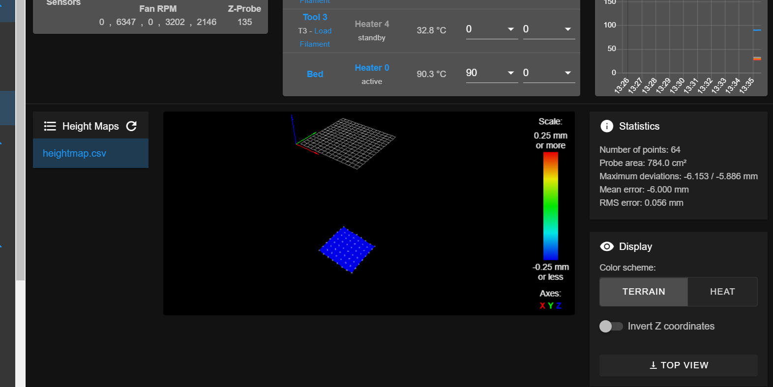
Strange highmap problemposted in Tuning and tweaking
Hi i have a slight problem adjusting my bed via meshbedleveling. Out of some strange behavior my G29 responds with a highmap some 5 or 6mm too deep. Mean deviation is acceptable, but i don't now if this works for printing in Case of compensating.
Here is a picture of the highmap:
Here is my config:
; Configuration file for Duet 3 (firmware version 3)
; executed by the firmware on start-up
;
; generated by RepRapFirmware Configuration Tool v3.2.3 on Fri Mar 12 2021 17:14:12 GMT+0100 (Mitteleuropäische Normalzeit)

; General preferences
G4 S1
G90                                                                        ; send absolute coordinates...
M83                                                                        ; ...but relative extruder moves
M550 P"ToolChanger"                                                        ; set printer name
M669 K1                                                                    ; select CoreXY mode

; Network
M552 P192.168.178.111 S1                                                           ; enable network and acquire dynamic address via DHCP
M586 P0 S1                                                                 ; enable HTTP
M586 P1 S0                                                                 ; disable FTP
M586 P2 S0                                                                 ; disable Telnet

; Drives
M569 P0.0 S1                                                               ; physical drive 0.0 goes forwards 				Drive 0 X
M569 P0.1 S1                                                               ; physical drive 0.1 goes forwards 				Drive 1 Y
M569 P0.2 S1                                                               ; physical drive 0.2 goes forwards 				Drive 2 Z
M569 P121.0 S1                                                             ; physical drive 121.0 goes forwards 			Drive Toolboard 121 E0
M569 P122.0 S1                                                             ; physical drive 122.0 goes forwards 			Drive Toolboard 120 E1
M569 P0.3 S0                                                               ; physical drive 0.3 goes forwards 				Drive 3 E2
M569 P0.4 S0                                                               ; physical drive 0.4 goes forwards 				Drive 4 E3
M569 P0.5 S0                                                               ; physical drive 0.5 goes forwards 				Drive 5 Coupler


M584 X0.0 Y0.1 Z0.2 C0.5 E121.0:122.0:0.3:0.4                              ; set drive mapping

M350 C8 I0                                                                 ; configure microstepping without interpolation
M350 X16 Y16 Z16 E16:16:16:16 I1                                           ; configure microstepping with interpolation
M92 X80.14 Y80.14 Z1600.00 C100 E417.10:417.10:466.793:466.793             ; set steps per mm
M566 X400 Y400 Z8.00 C2 E40:40:6000:6000                                       ; set maximum instantaneous speed changes (mm/min)
M203 X35000 Y35000 Z1200 C5000 E6000:6000:6000:6000                        ; set maximum speeds (mm/min)
M201 X6000.00 Y6000.00 Z400.00 C400 E1200.00:1200.00:6500.00:6500.00       ; set accelerations (mm/s^2)
M906 X1800 Y1800 Z1330 C400 E1200:1200:1200:1200 I30                       ; set motor currents (mA) and motor idle factor in per cent
M84 S120                                                                   ; Set idle timeout

;Stall Detection
M915 C S5 F0 H200 	  												    	; Coupler

;Stall Detection
M915 X Y S4 F0 H400 												     	; X / Y Axes

; Axis Limits
M208 X-56.5 Y-57.5 Z-6 C0 S1                                               ; set axis minima
M208 X353.5 Y360 Z308 C260 S0                                                ; set axis maxima

; Endstops
M574 X1 S3                                                                 ; configure sensorless endstop for low end on X
M574 Y1 S3                                                                 ; configure sensorless endstop for low end on Y
M574 Z1 S2				                                                   ; configure active-high endstop for low end on Z via pin io2.in

; Z-Probe
;M558 P1 R1 C"!io3.in" H10 F2400 A4 S0.05 T6000                                      ; set Z probe type to effector and the dive height + speeds NORMALERWEISE S0.03
M558 P1 R1.0 C"!io3.in" H7 F500 T10000                                      ; set Z probe type to effector and the dive height + speeds
G31 P500 X0 Y0 Z0                                                         ; set Z probe trigger value, offset and trigger height
M557 X5:295 Y5:295 S40                                                     ; define mesh grid

; Heaters
;Bed
M308 S0 P"temp0" Y"pt1000"                                                 ; configure sensor 0 as PT1000 on pin temp0
M950 H0 C"out0" T0                                                         ; create bed heater output on out0 and map it to sensor 0
M307 H0 B0 S1.00                                                           ; disable bang-bang mode for the bed heater and set PWM limit
M140 H0                                                                    ; map heated bed to heater 0
M143 H0 S125                                                               ; set temperature limit for heater 0 to 125C

;Extruder 0
M308 S1 P"121.temp0" Y"pt1000"                                             ; configure sensor 1 as PT1000 on pin 121.temp0
M950 H1 C"121.out0" T1                                                     ; create nozzle heater output on 121.out0 and map it to sensor 1
M307 H1 B0 S1.00                                                           ; disable bang-bang mode for heater  and set PWM limit
M143 H1 S350                                                               ; set temperature limit for heater 1 to 350C

;Extruder 1
M308 S2 P"122.temp0" Y"pt1000"                                             ; configure sensor 2 as PT1000 on pin 122.temp0
M950 H2 C"122.out0" T2                                                     ; create nozzle heater output on 122.out0 and map it to sensor 2
M307 H2 B0 S1.00                                                           ; disable bang-bang mode for heater  and set PWM limit
M143 H2 S350                                                               ; set temperature limit for heater 2 to 350C

;Extruder 2
M308 S3 P"spi.cs0" Y"rtd-max31865"                                         ; configure sensor 3 as thermocouple via CS pin spi.cs0
M950 H3 C"out1" T3                                                         ; create nozzle heater output on out1 and map it to sensor 3
M307 H3 B0 S1.00                                                           ; disable bang-bang mode for heater  and set PWM limit
M143 H3 S350                                                               ; set temperature limit for heater 3 to 350C

;Extruder 3
M308 S4 P"spi.cs1" Y"rtd-max31865"                                         ; configure sensor 4 as thermocouple via CS pin spi.cs1
M950 H4 C"out2" T4                                                         ; create nozzle heater output on out2 and map it to sensor 4
M307 H4 B0 S1.00                                                           ; disable bang-bang mode for heater  and set PWM limit
M143 H4 S350                                                               ; set temperature limit for heater 4 to 350C

; Fans
M950 F0 C"121.out2+out2.tach" Q2500                                        ; create fan 0 on pin 121.out1 and set its frequency
M106 P0 C"Tool 1 Lüfter" S1 H1 T45                                         ; set fan 0 name and value. Thermostatic control is turned on

M950 F1 C"122.out2+out2.tach" Q2500                                        ; create fan 1 on pin 121.out2 and set its frequency
M106 P1 C"Tool 2 Lüfter" S1 H2 T45                                         ; set fan 1 name and value. Thermostatic control is turned on

M950 F2 C"out9" Q500													   ; create fan 2 on pin out7 and set its frequency
M106 P2 C"Bauteilkühlung 1" S0 H-1                                         ; set fan 2 name and value. Thermostatic control is turned off

M950 F3 C"out5+out5.tach" Q500                                             ; create fan 3 on pin out8 and set its frequency
M106 P3 C"Bauteilkühlung 2" S0 H-1                                         ; set fan 3 name and value. Thermostatic control is turned off

M950 F4 C"out8" Q2500                                                      ; create fan 4 on pin out9 and set its frequency
M106 P4 C"Tool 3 Lüfter" S1 H3 T45                                         ; set fan 4 name and value. Thermostatic control is turned on

M950 F5 C"out7" Q2500                      		                           ; create fan 5 on pin out4 and set its frequency
M106 P5 C"Tool 4 Lüfter" S1 H4 T45                                         ; set fan 5 name and value. Thermostatic control is turned on

M950 F6 C"out4+out4.tach" Q25000                                           ; create fan 5 on pin out5 and set its frequency
M106 P6 C"Boardkühlung 1" S1 H1:2:3:4 T45                                  ; set fan 6 name and value. Thermostatic control is turned on

M950 F7 C"!out6+out6.tach" Q25000                                          ; create fan 6 on pin out6 and set its frequency
M106 P7 C"Gehäusekühlung" S1 H1:2:3:4 T45                                  ; set fan 7 name and value. Thermostatic control is turned on

; Tools
M563 P0 D0 H1 F0:2:3                                                       ; define tool 0
G10 P0 X0 Y0 Z0                                                            ; set tool 0 axis offsets
G10 P0 R0 S0                                                               ; set initial tool 0 active and standby temperatures to 0C

M563 P1 D1 H2 F0:2:3                                                       ; define tool 1
G10 P1 X0 Y0 Z0                                                            ; set tool 1 axis offsets
G10 P1 R0 S0                                                               ; set initial tool 1 active and standby temperatures to 0C

M563 P2 D2 H3 F0:2:3                                                       ; define tool 2
G10 P2 X0 Y0 Z0                                                            ; set tool 2 axis offsets
G10 P2 R0 S0                                                               ; set initial tool 2 active and standby temperatures to 0C

M563 P3 D3 H4 F0:2:3                                                       ; define tool 3
G10 P3 X0 Y0 Z0                                                            ; set tool 3 axis offsets
G10 P3 R0 S0                                                               ; set initial tool 3 active and standby temperatures to 0C

; Custom settings
M593 F50					                                               ; cancel ringing at 50Hz (https://forum.e3d-online.com/threads/accelerometer-and-resonance-measurements-of-the-motion-system.3445/)
M376 H15					                                               ; bed compensation taper

;tool offsets
G10 P0 X19.8 Y58 Z-3.275		                                           ; T0 Hemera 0.5mm Nozzle
G10 P1 X18.8 Y58 Z-3.1				                                       ; T1 Hemera 0.4mm Nozzle
G10 P2 X-9 Y39 Z-3.44				                                       ; T2 E3D V6 Bondtech 0.4mm Nozzle
G10 P3 X-9 Y39 Z-5.39				                                       ; T3 Prometheus Bondtech 0.4mm Nozzle

; Deselect tools
T-1

; Pressure Advance
M572 D0 S0.05 					                                           ; pressure advance T0
M572 D1 S0.05 					                                           ; pressure advance T1
M572 D2 S0.2 					                                           ; pressure advance T2
M572 D3 S0.2 					                                           ; pressure advance T3

; Heater model parameters
M307 H0 B0 R0.162 C1661.3 D30.91 S1.00 V24.0
M307 H1 B0 R2.147 C289.1:220.0 D5.22 S1.00 V23.7
M307 H2 B0 R2.322 C197.6:173.7 D5.69 S1.00 V23.6
M307 H3 R1.607 C273.7:225.8 D6.01 S1.00 V23.9
M307 H4 R2.114 C239.508:194.630 D7.77 S1.00 V23.9 B0 I0

; Miscellaneous
M575 P1 S1 B57600                                                          ; enable support for PanelDue
M501                                                                       ; load saved parameters from non-volatile memory
M911 S20 R23 P"M913 X0 Y0 G91 M83 G1 Z3 E-5 F1000"                         ; set voltage thresholds and actions to run on power loss
here is my bed.g:
; Bed Mesh Leveling

G28 Z

G1 S2 Z3 F500		; lift Z 3mm

;G31 P{sensors.probes[0].value[0] + 15}							;for analog reading of precision Piezo
G29

;disable mesh leveling, needs to be enabled at the start of your print and disabled again when finished.
G29 S2

; Park the head
G1 X-20 Y0 F50000
here is my homeall:
; homeall.g
; called to home all axes

M98 Phomec.g			; Home C (ToolHead)

M98 Phomey.g			; Home Y

M98 Phomex.g			; Home X

M98 Phomez.g			; Home Z

G1 X-20 Y-0 Z5 F15000		; Park
here is my homec:
; homec.g
; called to home the C axis (coupler)

;crashc
G92 C260
M913 C50			; C MOTOR TO 40% CURRENT
G1 C-260 F2400  ; drive the C-axis to the stop
M913 C100			; C MOTOR TO 100% CURRENT
G1 C1 F50000
G92 C0

;Open Coupler
M98 P/macros/Coupler - Unlock
here is my homex:
; homex.g
; called to home the x axis

G91 			; use relative positioning

G1 H2 X0.5 Y-0.5 F10000		; energise to avaoid false triggers during sensorless homing

M400 			; make sure everything has stopped before we make changes
G4 P100			; wait 100ms

M913 X30 Y30 		; drop motor currents to 50%
M915 H200 X Y S2 R0 F0 	; set X and Y to sensitivity 3, do nothing when stall, unfiltered

G1 H2 Z3 F5000		; lift Z 3mm
G1 H1 X-400 F3000 	; move left 400mm, stopping at the endstop
G1 H1 X2 F2000 		; move away from end
G1 H2 Z-3 F1200		; lower Z
G90 			; back to absolute positioning

M400 			; make sure everything has stopped before we reset the motor currents
G4 P100			; wait 100ms
M913 X100 Y100 		; motor currents back to 100%
here is my homey:
; homey.g
; called to home the Y axis

G91 			; use relative positioning

G1 H2 X0.5 Y-0.5 F10000		; energise to avaoid false triggers during sensorless homing

M400 			; make sure everything has stopped before we make changes
G4 P100			; wait 100ms

M913 X30 Y30 		; drop motor currents to 20%
M915 H200 X Y S2 R0 F0 	; set X and Y to sensitivity 3, do nothing when stall, unfiltered


G1 H2 Z3 F5000		; lift Z 3mm
G1 H1 Y-400 F3000 	; move to the front 400mm, stopping at the endstop
G1 H1 Y2 F2000 		; move away from end
G1 H2 Z-3 F1200		; lower Z
G90 			; back to absolute positioning

M400 			; make sure everything has stopped before we reset the motor currents
G4 P100			; wait 100ms
M913 X100 Y100 		; motor currents back to 100%
here is my homez:
; homez.g
; called to home the Z axis

T-1       ;just in case there is a tool coupled, go try to drop it at the dock

M98 P/macros/Coupler - Unlock	;Open Coupler

G91 				; Relative mode
G1 H2 Z5 F5000			; Lower the bed
G90				; back to absolute positioning

G1 X150 Y150 F50000		; Position the endstop above the bed centre

G91 				; Relative mode

G4 P1000				; wait 500msec
;G31 P{sensors.probes[0].value[0] + 15}
;G30                     ; Probe the bed at the current XY position.
                        ; When the probe is triggered, set the Z coordinate
						; to the probe trigger height.
G1 Z-300 H1 F500		; Move Z down until the switch triggers (first pass)

G4 P100				; wait 100msec
G1 Z5 F2400			; Lift Z

G4 P1000				; wait 100msec
;G31 P{sensors.probes[0].value[0] + 50}
;G30                     ; Probe the bed at the current XY position.
                        ; When the probe is triggered, set the Z coordinate
						; to the probe trigger height.
G1 Z-300 H1 F500		; Move Z down until the switch triggers (second pass)

G4 P100				; wait 100msec
G1 Z5 F5000			; Drop the Bed

G90				; Back to absolute positioning
and here is for example my tool0 pre, post and free:
; tfree0.g
; called when tool 0 is freed

;Drop the bed
G91
G1 Z4 F1000
G90

;mesh levelling off
G29 S2

;Purge nozzle
;M98 Ppurge_r.g

;Move In
G53 G1 X320.9 Y280 F50000
G53 G1 Y307 F50000
G53 G1 Y332.5 F5000

;Open Coupler
M98 P/macros/Coupler - Unlock

;fan off
M106 P2 S0

;Move Out
G53 G1 Y280 F50000
; tpost0.g ; called after tool 0 has been selected ;heatup M116 P0 ;prime nozzle ;M98 Pprime_r.g ;mesh levelling on G29 S1 ;PCF fan on M106 P2 R2; tpre0.g ; called before tool 0 is selected ;Unlock Coupler M98 P/macros/Coupler - Unlock ;Move to location G1 X320.5 Y280 F50000 ;Move in G1 Y307 F50000 ;Collect G1 Y332.5 F2500 ;Close Coupler M98 P/macros/Coupler - Lock ;WARNING! WARNING! WARNING! WARNING! WARNING! WARNING! WARNING! WARNING! WARNING! WARNING! WARNING! WARNING! ;if you are using non-standard length hotends ensure the bed is lowered enough BEFORE undocking the tool! G91 G1 Z10 F1000 G90 ;Move Out G1 Y280 F4000and last but not least here is my Highmap
RepRapFirmware height map file v2, min error -6.153, max error -5.886, mean -6.000, deviation 0.056
axis0,axis1,min0,max0,min1,max1,radius,spacing0,spacing1,num0,num1
X,Y,5.00,295.00,5.00,295.00,-1.00,40.00,40.00,8,8
 -5.919, -5.969, -5.986, -5.986, -5.994, -6.052, -6.036, -5.969
 -5.911, -5.952, -5.961, -5.969, -5.986, -6.028, -6.028, -5.961
 -5.886, -5.952, -5.969, -5.977, -6.003, -6.028, -6.036, -5.961
 -5.894, -5.952, -5.969, -5.986, -5.986, -6.052, -6.036, -5.969
 -5.903, -5.961, -5.969, -5.961, -5.994, -6.028, -6.052, -5.977
 -5.903, -5.961, -5.969, -5.977, -5.994, -6.061, -6.077, -6.011
 -5.944, -6.003, -6.028, -6.011, -6.036, -6.094, -6.111, -6.036
 -6.003, -6.044, -6.069, -6.036, -6.077, -6.119, -6.153, -6.102
My Question is, what did i do wrong here?
My printer is a self build toolchanger. Has 4 tools and a build volume of 300mm³.Thx for the help.
-
RE: Designing a PWM to Analog mini board for fansposted in Tuning and tweaking
If there are any Boards left, icould use 4 of the.
-
RE: temp controlled Fans on Duet3 6HC driving me crazyposted in General Discussion
Ok i think i got it to work.
The toolboard are not working flawlessley.That was because of the line:
M950 F0 C"121.out2+121.out2.tach" Q25000                                        ; create fan 0 on pin 121.out1 and set its frequency
M106 P0 C"Tool 1 Lüfter" S1 H1 T45
wich needed to look like this:
M950 F0 C"121.out2+out2.tach" Q25000                                        ; create fan 0 on pin 121.out1 and set its frequency
M106 P0 C"Tool 1 Lüfter" S1 H1 T45
Now i wil try to repin from 3 to 4 pin Socket on the Board-Fans to look if i can solve that problem there too.
edit on:
Jep that pinning helped thx very much for the Info.
edit off.
-
RE: temp controlled Fans on Duet3 6HC driving me crazyposted in General Discussion
If you wish to control them change to: black -> out6
ok will try that, but thats wiered becouse all 3-Pin headers on the normal PC-fans will only fit like that so i have to unpin them is that right?
From the DWC console please execute M98 P"config.g" and report to us any warnings or errors that may appear on the console.
M98 P"config.g"
HTTP is enabled on port 80
FTP is disabled
TELNET is disabled
Error: in file macro line 35 column 38: M566: array too long, max length = 4
Error: Unknown pin name '121.out2.tach'
Error: Fan number 0 not found
Error: Unknown pin name '122.out2.tach'
Error: Fan number 1 not found
Warning: Heater 0 appears to be over-powered. If left on at full power, its temperature is predicted to reach 377C
Warning: Heater 1 appears to be over-powered. If left on at full power, its temperature is predicted to reach 647C
Warning: Macro file config-override.g not found
looks like there are some errors in it will investigate that
The Q parameter of 25000 is greater than I normally use. Have you tried something like 2500?
also tryed 500 which is the standard value, only switched it to 25000 because i thought pc fans have a PWM frequency of 25000Hz
Thanks
Kai -
temp controlled Fans on Duet3 6HC driving me crazyposted in General Discussion
Hi i have a Duet 3 6HC with a distribution board an two Toolboards (1LC).
At the moment i have layed the hardware out on the Table connectec together without an printer attachet.
I wanted to programm the board in forefront to save some hassle.I ran into some issues. When i try to control the fans for the electronics compartment and the coldends with thermostatic control enabled.
They all stay on all the time or doesnt want to run at all.I lowered the threshold of the Temperature to around 15°C when the tempreture probe showed 20°C but the fans wouldnt turn on.
For the coldend fans i use 40x40x10mm Noctua 3-wire Fans connected to the toolboard on out 2 (Both board have a uniqe CAN adress 121 and 122). For the Compartment i am runnung 60x60x20 Noctua 3-wire Fans connected to the connections out4 - out6.
What did i do wrong? I think i messed up some programming or wirering.
Here is my Config.g: config (4).g
On the Toolboard the fans are wired like this: black -> out2, red -> +12V, yellow -> out2.tach
On the 6HC they are wired like this: black -> GND, red -> V_OUTLC1, yellow -> out6.tachAn i have a nother question the toolboard isn't tranfering the tacho signal thru. on all the other Fans that is the case and they are shown in the DWC.
Any suggestions?Thanks fo the Help.
-
RE: Precision Piezo troublesposted in Third-party add-ons
How long are the cables from your piezo to the board?
Make shure that these wires are as short as possible.
You can also replase these small fiddly resistors with a nicer to adjust one like this.
Is your piezo Modul an original one or is it a clone?Make sure you adjust your VR1 to a value of 0.4MOhm this the recommended, from there you should start to adjust VR2 until it lights then back off to where the LED goes out.
Hope this helps. Yes its a little fiddly but if its dialed in then there is nothing like it.
greetings
Kai -
RE: Can't Update or connect to Wifi with my DuetWifiposted in General Discussion
"Error:Installation failed due to comm write error"
But before that i tries to connect at all possible baud rates.
-
Can't Update or connect to Wifi with my DuetWifiposted in General Discussion
Hi there,
im having my difficulties with the Wifi Module lateley.
All worked fine with the the Firmware 2.0 beta 1-3.
All on DuetWifiServer 1.21 und DuetWebControl 1.21.
But suddenly my Duet won't connect to any wifi anymore. So i tried to send M552 S1 over my PanelDue, but all i was reciving was "Error: Failed to initialise WiFi module, code -10".
So first idea was ok, back up to DuetCombinedFirmware 1.21.
But this hadn't changed anything, so i tried to update the DuetWifiServer again to 1.21 maybe somthing was corrupted over time, who knows.
But then the i was shocked, because my paneldue tried to connect to the Wifi Module but it coud not establis a COM connection.Oh by the way my Hardwareversion on the DuetWifi is 1.02
What can i do now?
What could be causing this problem?greetings
Kai -
RE: Bed leveling on DuetWifi+Duex5 using 4 independent Z motorsposted in General Discussion
Hi the Linear rails/bars are provide the Stability an accuracy and the Screws provide the movement/motion of the system. No screw is that accurate that you dont have an possibly x/y movement of the table.