Duet3D Logo Duet3D
    • Tags
    • Documentation
    • Order
    • Register
    • Login
    1. Home
    2. Sphyloid
    3. Posts
    • Profile
    • Following 0
    • Followers 0
    • Topics 19
    • Posts 52
    • Best 8
    • Controversial 0
    • Groups 0

    Posts made by Sphyloid

    • RE: Tool Specific M675 For Automatic XY tool offsets

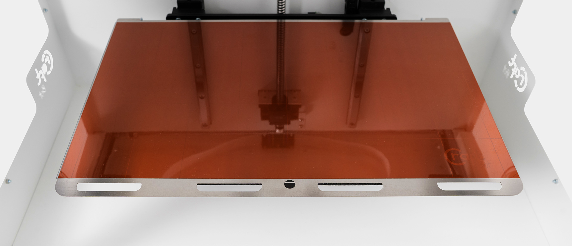
      @dc42 The whole point of what I am asking is that the tool offsets are found automatically without the need for the user to print a veneer or any other shenanigans. The cavity is only available on the first layer.

      775eb304-498a-4b44-ac44-cf6c443f9483-image.png

      This is a machine that has an identical feature. They allow the user to run probing on that cavity when the machine falls out of calibration instead of having to waste tons of time finding offsets. The machine then stores these values.

      My idea behind running this homing at the start of each print is simply so that the user never has to worry about the machine falling out of calibration, making the alignment completely hands-free, completely automatically. The user simply has effortless dual material printing experience.

      The next step is enabling servo lifting on the two nozzles so that they automatically maintain themselves in that axis.

      In my case I have 10 idex machines. I have not ever considered using dual material mode as maintaining an accurate calibration on 10 machines is completely unsustainable without it being automatic or wasting tons and tons of time. Adding a cavity to probe? Now that is a cakewalk.

      posted in Gcode meta commands
      Sphyloidundefined
      Sphyloid
    • RE: Tool Specific M675 For Automatic XY tool offsets

      @rjenkinsgb It seems you missed the "automatic" part of what I was saying. The user should never have to manually set offsets, they change over time and it is a giant pain. Sure you can design a sufficiently precise printer that does not change, but that is too expensive which is why it has not been done.

      I have a circle with a center point at a known location cut into my build plate. I want to drop the nozzle in the hole and capacitive home all the tools at the start of each print. If I home them consecutively in the hole with M675 as the command works now only the last tool homed will print in the "right" place relative to the hole.

      Maybe I do not want to home in this way before every print, it would be nice to additionally save the offsets generated by this.

      posted in Gcode meta commands
      Sphyloidundefined
      Sphyloid
    • Tool Specific M675 For Automatic XY tool offsets

      Title says it all, I want a version of M675 that stores tool specific offsets. As you are printing you cannot keep re-homing each time you change a tool, you would collide with the part.

      One way this could work is the first tool is homed using "M675 Y T0 R2 F1200" which acts like a normal homing. If a tool other than 0 is used for initial homing, then it becomes the arbitrary 'true home' the tool from which all the rest are relative too. Then say tool 2 is homed with: "M675 Y T1 R2 F1200" next T2, T3 etc. Instead of homing the next tools, their offset from the original homing would be recorded.

      Please add this functionality or give me a brief high level description of how I would implement something like this in my own fork.

      posted in Gcode meta commands
      Sphyloidundefined
      Sphyloid
    • RE: IDEX/multi extruder auto calibration

      @droftarts Actually, that does exactly what I am looking for. A while ago I read the entire gcode dictionary for the duet, and since I did not see any similar posts on the forums I assumed it was not added yet. This makes things easier for me!

      posted in Firmware installation
      Sphyloidundefined
      Sphyloid
    • IDEX/multi extruder auto calibration

      Hi I want to cut a circular feature into my build plate. The center point will be a known location. The build plate will be connected to 3.3v and both nozzles will be connected to an endstop signals. Using really slow movements I want to use each nozzle to probe the sides of the circular feature to find their offsets.

      I need a way of recording the distance between the endstop being triggered the first and second time on X, then the distance between the first and second time on Y. Then I need to do maths on these values to find the offsets, then I need to use these offsets and apply them in the firmware.

      Both E0 and E1 will need offsets stored since they will be relative to this feature.

      This feature will usher in a next level in multi extruder print quality and ease of use on the duet. It's importance cannot be understated given the incoming era of multi extruder machines prusa is kickstarting.

      alt text

      The next step is enabling nozzle lifting on the second nozzle, but that is for later.

      posted in Firmware installation
      Sphyloidundefined
      Sphyloid
    • RE: Duet Wifi 2 Panucatt Viki 2 / VIKI2 setup

      @dc42 Thanks for the help, I just created a guide incase anyone else tries to do this: https://duet3d.dozuki.com/Guide/Panucatt+Viki+2+-+VIKI2+setup/111

      posted in Duet Hardware and wiring
      Sphyloidundefined
      Sphyloid
    • RE: Duet Wifi 2 Panucatt Viki 2 / VIKI2 setup

      @sphyloid VIKI2 is 100% compatible. 🙂 just need to wire it properly, call it in config.g and create the menus.

      Duet 2 SD and LCD port Pinouts ( For Reference )

      DuetDisplay.JPG

      Correct Pin Placements

      VIKI2toDuet2.JPG

      VIKI2 Pinout ( For Reference )

      VIKI2pinout.JPG

      Never found a place for the red and blue LEDs from what I read I do not think P5 the neopix pin will work for one of them. Maybe ill connect them to fans or something if they work not sure. If they are logic only I could run them through the expansion but I strongly suspect they need to be powered.

      #define DEFAULT_LCD_CONTRAST 40
      #endif
      
      #define ENCODER_PULSES_PER_STEP 4
      #define ENCODER_STEPS_PER_MENU_ITEM 1
      

      Grabbed this from the default marlin firmware from the AW3D Axiome. From this I believe the following would be the correct:

      M918 P2 E4 C40

      Great, it is working now! Just need to setup the menu
      https://duet3d.dozuki.com/Wiki/Duet_2_Maestro_12864_display_menu_system

      The Ultimate Duet Menu by Jadon Miller comes HIGHLY recommended by me.
      https://github.com/jadonmmiller/UltimateDuetMenuSystem

      posted in Duet Hardware and wiring
      Sphyloidundefined
      Sphyloid
    • RE: Duet Wifi 2 Panucatt Viki 2 / VIKI2 setup

      @dc42 When looking at the marlin firmware originally compiled for the AW3D Axiome I saw that calling VIKI2 calls Ultralcd which is the backbone for ST7920. However when double checking it also calls DOGLCD, the backbone for ST7567. So I have no idea honestly

      posted in Duet Hardware and wiring
      Sphyloidundefined
      Sphyloid
    • RE: Duet Wifi 2 Panucatt Viki 2 / VIKI2 setup

      @sphyloid I could not get the Viki 2 working with the duet wifi 2. However I did have the paneldue enabled in firmware.

      After switching to 3.3v, the backlight did turn on despite only being powered with 3.3v, but nothing showed on the display. Paneldue was enabled upstream of where I enabled the encoder display, so it should have been overridden.

      I tried 2Mhz, 0.5Mhz, and 60hz. Nothing showed on any of them.

      Your mileage may vary, Im not exactly a pro.

      As of right now I prefer paneldue and had one lying around so Im just using that. Too fustrated with re-setting up the wiring loom to bother trying again with paneldue disabled. It likely will not work anyway.

      posted in Duet Hardware and wiring
      Sphyloidundefined
      Sphyloid
    • Duet Wifi 2 Panucatt Viki 2 / VIKI2 setup

      EDIT: I got it working, you can too. All the info you need is in one of my replies.

      https://www.panucatt.com/product_p/vikilcd2.htm

      This seems to be a special case ST7920 that is set up to accept 3.3v input. It has a jumper input voltage select with an option for 3.3v and 5v with the default set to 5v.

      Any words of caution before I follow the guide here?: https://duet3d.dozuki.com/Wiki/Connecting_an_LCD_control_panel#Section_Connecting_a_12864_mono_graphics_LCD_display_with_rotary_encoder

      posted in Duet Hardware and wiring
      Sphyloidundefined
      Sphyloid
    • RE: Z Probe is off the bed at X0 Y0 so autolevel does not work

      @rjenkinsgb Thanks, when I read the write up on editing G30 from dc42 I thought that editing G30 would set the expected Z value at that location, but I did not realize he was talking from the perspective that XY values would change where it probed.

      Thanks!

      posted in Firmware installation
      Sphyloidundefined
      Sphyloid
    • Z Probe is off the bed at X0 Y0 so autolevel does not work

      Title says it all. I need to be able to set the initial probing point before doing an auto level because my probe is at X -18.75. Solidly off the build plate. Also god forbid G30 is ever run on the machine, if there were a way to make that probe a location actually on the build plate that would be great.

      Moving the Z probe to the other side is not possible without a ton of work.

      posted in Firmware installation
      Sphyloidundefined
      Sphyloid
    • Peltier Cooled Heated bed

      Running an automated 3D printer that uses a heat differential to release parts, much time is spent waiting for the bed to cool down. Right now I am looking at setting up a heated bed that uses peltiers.

      In order to remove the complication of reversing the voltage, I plan to have 2 series of 10X 50w peltier coolers on a 350mm square bed of a voron. Under the peltiers I plan on having a set of waterblocks. The reservoir will have an emersion heater in order to raise the temperature of the water block side to 60-70C so that the heated bed can easily hit 90-100C.

      Theoretically, at this point we are talking about 3 circuits to control the temperature of the bed. Heating peltiers 500W 12VDC, Cooling peltiers 500W 12VDC, emersion heater 1500W 120VAC.

      I can figure out the hardware side of enabling the three circuits. However the software side has me puzzled. It seems to me that the duet firmware fundamentally only supports active circuits for heating circuits, not cooling circuits. From where I stand it looks like I would have to configure a servo channel, activate it when I want cooling, use a wait for temp command, remove the part with the gantry, then disable the servo channel.

      Any ideas?

      One I came up with was that I would be better served using a traditional heating method and connecting the water block directly to the heated bed. Turning the pump on when I wanted to cool it off.

      posted in Duet Hardware and wiring
      Sphyloidundefined
      Sphyloid
    • ALM and PEND Signals from External Drivers

      Making an expansion board for the Duet 2 Wifi specifically for external drivers. These steppers have integrated optical encoders and the drivers have PEND and ALM signals. They operate with the same signal as an endstop, open or closed pulled up to whatever voltage I like.

      With the PEND and ALM signal for 6 drives that quickly adds up to 12 signals.

      Since this board will have a SX1509BIULTRT extender chip which give me endstop signals, can I use the CS5-8 from the expansion slot and GPIO1-4 for the signals? Granted this still only gives me 8 signals, but since I personally only intend on using 4 motors in situations where they could lose steps this would be totally passable.

      Worst case I can omit the signals, however this is not the preferred solution.

      Best case someone knows how I can get 12 signal pins to connect them all to.

      posted in Duet Hardware and wiring
      Sphyloidundefined
      Sphyloid
    • Duex I2C Pin 10 OR Resistor

      Cannot seem to figure out what this OR resistor is. From what I can see on the sparkfun breakout board schematic and the documentation on the SX1509B it feels like this should be a solder bridge. Obviously this is not a solder bridge.

      ORResistor.png

      duexP10.PNG

      sparkfunP10.PNG

      posted in Duet Hardware and wiring
      Sphyloidundefined
      Sphyloid
    • RE: What Rectifier is used for Fans on DUEX

      @sphyloid Look in the duet 2 wifi schematic, it has the info in the properties. http://uk.farnell.com/taiwan-semiconductor/es1cl/diode-ultra-fast-s1a-150v/dp/1559125

      posted in Duet Hardware and wiring
      Sphyloidundefined
      Sphyloid
    • What Rectifier is used for Fans on DUEX

      ES1CL R3G

      http://uk.farnell.com/taiwan-semiconductor/es1cl/diode-ultra-fast-s1a-150v/dp/1559125

      fanMos.PNG

      posted in Duet Hardware and wiring
      Sphyloidundefined
      Sphyloid
    • RE: Duex I2C Hardware Configuration

      @t3p3tony That almost cleared everything up. Just 3 last minor details.

      • What is the capacitor capacity
        ?Pin 18 gets connected to 3.3v and has a 0u1 capacitor connecting it to ground

      • What LED is used on the endstops, I assume its not too critical

      • Is Pin 4 of the EXP remapped from e2.stop to something related to Stallguard? It is labeled E2_TST gets put into a 74HC32 under the Stallguard OR schematic and then sent over to one of the step drivers. If it is, can I simply omit this? The external drivers I am using are self managing so I assume yes.

      posted in Duet Hardware and wiring
      Sphyloidundefined
      Sphyloid
    • RE: Duex I2C Hardware Configuration

      @sphyloid Just use a different spreadsheet program, I am sure kiCAD is not broken.

      -Signed future you

      posted in Duet Hardware and wiring
      Sphyloidundefined
      Sphyloid