@fcwilt Exactly what I needed to get past my mental roadblock. Some small code blocks doing just what I need. Now to refine the hardware to go with it. Most appreciated Gilly
Posts made by Strider007
-
RE: Need help changing an X or Y coordinate into a variableposted in Gcode meta commands
-
RE: Need help changing an X or Y coordinate into a variableposted in Gcode meta commands
@fcwilt
Yes, when I echo, that is the number I want to store as a temp variable then use in calculations of tool offsets.echo "it is", move.axes[0].machinePosition
it is -118.088Thank you for your guidance. I believe I 've got it from here.
-
RE: Need help changing an X or Y coordinate into a variableposted in Gcode meta commands
@Strider007 Ok, now studying M409, and I think I got this working.
Thanks all
-
RE: Need help changing an X or Y coordinate into a variableposted in Gcode meta commands
@zuoyan
Its a long list, and I've looked through it multiple times. I probably should have mentioned that. That's when I found the two suggestions that fcwilt gave me but no success so far. Thanks -
RE: Need help changing an X or Y coordinate into a variableposted in Gcode meta commands
@fcwilt Thanks,
Ok, tried all combinations of your suggestions and only got error messages as follows:move.axes[0].machinePosition
Error: Bad command: move.axes[0].
Error: Bad command: machinePositionI had hoped that would work and had tried it already. What am I missing here?
I
-
RE: Need help changing an X or Y coordinate into a variableposted in Gcode meta commands
@fcwilt Yes, I send a "G38.2 X10 F100" command, the machine moves until the sensor is tripped and stops. I want that exact X coordinate where it stopped as a number to be used in in alignment calculations.
-
Need help changing an X or Y coordinate into a variableposted in Gcode meta commands
I need to be able to take an unknown X or Y coordinate and set it as a variable in a macro.
I'm using the G38.2 command to find an edge for use in a calculation. The G38.2 command works as expected and stops correctly at the location it is triggered. I can see the X and Y locations on the DWC or by using a M114 command but I do not understand how to change that into a variable I can use in a macro for a calibration calculation.
With a G30 command I can get the Z coordinate using
"global.autoz_tempx0 = sensors.probes[0].lastStopHeightHow can I accomplish this with the G38.2 command, having it provide the X or Y coordinate?
Any help or direction would be greatly appreciated.
-
RE: Bed heater switches to standby randomly while printingposted in Duet Hardware and wiring
@Phaedrux
Thank you. I currently use Cura 5.5.0. I will look over the several files that have exhibited this issue today but I run those same files on two other machines with no bed heater issues. Only this machine exhibits the unreported fault. That is the reason I believe it is something with this specific motherboard rather than the files. It does have driver0 damage; perhaps an EOS event hurt the processor.Can anyone suggest any diagnostics I could run while printing that might catch this fault? I'm assuming there is a latch or memory location that holds the "heater active" data. Can that be monitored, and capture what's going on?
Yes Cura calls Reprap during file generation.
-
RE: Bed heater switches to standby randomly while printingposted in Duet Hardware and wiring
@jay_s_uk
I considered that but the same gcode files print fine on my other two machines. It is only this machine that has this issue. This totally random. Some times it holds and performs normally, other times, it will switch the bed to standby before the print starts. I have done several prints where it dropped to standby multiple times. Setting bed standby to 94C is all that saves my prints. -
Bed heater switches to standby randomly while printingposted in Duet Hardware and wiring
I have an Ultimaker clone, with a used Duet 2 WIFI. The heater appears rock solid viewing DWC until it switches to standby. I see the temp drop on DWC or if looking at the PanelDue, the normally red indicator turns yellow. I get no heater fault, or message. If I use either the PanelDue or the DWC I can easily reset the bed temp back to active. I've been saving my prints by setting my bed standby temp to 93C (2 degrees below my desired active temp). So far it has not slipped past the standby temp but what is going on.
Note, the motherboard was purchase used from Europe and shipped over.It is a clone, and driver 0 was blown. Since I only need 4 drivers I just programmed around that issue.
The system runs on a 12v supply but the bed heater is powered by mains with a SSR-25 controlling it so I don't believe it to be momentary PS sag. Possibly a memory issue? Running RRF3.5.1. Here is my config for this system.
; Configuration file for Duet WiFi (firmware version 3.5.1)
; executed by the firmware on start-up
;

; General preferences
M575 P1 S1 B57600                              ; enable support for PanelDue
G90                                            ; send absolute coordinates...
M83                                            ; ...but relative extruder moves
M550 P"U-2"                             ; set printer name

; Network

; WIFI on for home network
M552 S1                                        ; enable network
M586 P0 S1                                     ; enable HTTP
; No WIFI for stand alone, network off
; M552 S0                                      ; disable network
; M586 P0 S0                                   ; disable HTTP

M586 P1 S0                                     ; disable FTP
M586 P2 S0                                     ; disable Telnet

; Drives
;  Driver P0 is not functional
M569 P1 S0                                     ; physical drive 1 goes backwards
M569 P2 S1                                     ; physical drive 2 goes forwards
M569 P3 S1                                     ; physical drive 3 goes forwards
M569 P4 S0                                     ; physical drive 4 goes backwards
M584 X1 Y3 Z2 E4                               ; set drive mapping
M350 X16 Y16 Z16 E16 I1                        ; configure microstepping with interpolation
M92 X80.00 Y80.00 Z1600.00 E400.00             ; set steps per mm
M566 X900.00 Y900.00 Z60.00 E120.00            ; set maximum instantaneous speed changes (mm/min)
M203 X6000.00 Y6000.00 Z180.00 E1200.00        ; set maximum speeds (mm/min)
M201 X500.00 Y500.00 Z20.00 E250.00            ; set accelerations (mm/s^2)
M906 X900 Y900 Z900 E490 I30                   ; set motor currents (mA) and motor idle factor in per cent
M84 S90                                        ; Set idle timeout

; Axis Limits
M208 X-98 Y-120 Z0 S1                         ; set axis minima
M208 X112 Y90 Z300 S0                         ; set axis maxima

; Endstops
M574 X1 S1 P"!xstop"                            ; configure switch-type (microswitch) endstop for low end on X via pin xstop, active low
M574 Y2 S1 P"!ystop"                            ; configure switch-type (microswitch) endstop for high end on Y via pin ystop, active low
M574 Z1 S1 P"zstop"                            ; configure switch-type (Optical) endstop for low end on Z via pin zstop, active high

; Z-Probe
M558 P0 H5 F120 T6000                          ; disable Z probe but set dive height, probe speed and travel speed
M557 X-90:90 Y-90:90 S20                       ; define mesh grid

; Heaters
M308 S0 P"bedtemp" Y"thermistor" T100000 B4138 		; configure sensor 0 as thermistor on pin bedtemp
M950 H0 C"bedheat" T0                          		; create bed heater output on bedheat and map it to sensor 0
M307 H0 R0.766 K0.379:0.000 D2.01 E1.35 S1.00 B0	; Auto tune provided values for PID mode 11-2022
M140 H0                                        		; map heated bed to heater 0
M143 H0 S100 A2										; shut heater off temporarily if tripped
M143 H0 S110 A0                                 	; set temperature limit for heater 0 to 110C, set fault if tripped
M308 S1 P"e0temp" Y"thermistor" T100000 B4138  		; configure sensor 1 as thermistor on pin e0temp
M950 H1 C"e0heat" T1                           		; create nozzle heater output on e0heat and map it to sensor 1
M307 H1 R2.371 K0.338:0.000 D10.03 E1.35 S1.00 B0 V11.8		; parameters derived from Autotune on 11-2022 PID mode.
M143 H1 s250 A2										; shut heater off temporarily if tripped
M143 H1 S260                                   		; set temperature limit for heater 1 to 250C

; Fans
M950 F0 C"fan0"                                 ; create fan 0 on pin fan0 and set its frequency
M106 P0 S0.0 H1 T45                             ; set heatsink fan 0 value. Thermostatic control is turned on at 45C
M950 F1 C"fan1"                                 ; create fan 1 on pin fan1 and set its frequency
M106 P1 S0.0                                    ; set part cooling fan 1 value. Thermostatic control is turned off

; Tools
M563 P0 D0 H1 F1                               ; define tool 0
G10 P0 X0 Y0 Z0                                ; set tool 0 axis offsets
G10 P0 R0 S0                                   ; set initial tool 0 active and standby temperatures to 0C

; Custom settings are not defined
M501											; Use settings in override file that were dervived from Auto tuning system
Any insight would be appreciated.
-
RE: M291 J2 =-1 ?posted in Gcode meta commands
@droftarts , Yes I realize that now. I found feature request #959 and want to add my voice to the ones requesting this modification. I feel this change could add significant flexibility to M291 by opens up many different options regarding how a query is responded to, or not. Note that is my case I don't even need or want the extra cancel box, but I would live with it if I could get the cancel/timeout to work the way I want it to.
My reason for this request is that I want to reduce the amount of machine cycling as I call macros that contain activity that has already been done and has set flags as to have been completed. The idea is to go ahead and do the extra cycling if there is no response to the query, as a safety mechanism.
-
M291 J2 =-1 ?posted in Gcode meta commands
RRF 3.5.1
Duet WIFI Server 2.1.0
DWC 3.5.1
HW Duet2 WIFI/Duex5Is there any update on the M291 request with a J2 to return "-1"? I need timeouts to do something other than abort macro. Please add my voice asking to get it implemented.
This is what I would like to work:
M291 R"XYU already Homed" P"Home XYU Again" S4 K{"yes","no"} T5 J2
if input = 1
    echo "Skip Home XYU"
if input = 0
    echo "Home XYU"
if input = -1
    echo "Timed Out, Home XYU Anyway, or do something else"
echo input
I need the timeout to set the input = -1 but it always aborts. I thought my issue had been sorted out based on DC42’s comments in the post Meta gcode result variable inconsistent with docs but now realize this was just a feature request. I had hoped 3.5.1 with all the work done on M291 that J2=-1 might this incorporated too, but no.
I need any timeout, when with a J2, to set the input = -1, or at least some approach to implement a timeout of a question that is not abort.
Thanks for any input, I've been going in circles.
-
RE: CoreXY to IDEX conversion updateposted in My Duet controlled machine
FYI, this printer was just posted on Thingiverse as "Core IDX" or as thing:6224372.
-
RE: CoreXY to IDEX conversion updateposted in My Duet controlled machine
@Strider007 Here is a short U-Tube video of an ABS benchy
-
RE: CoreXY to IDEX conversion updateposted in My Duet controlled machine
@Strider007 This project started life as a Hypercube HEVO kit with linear rails for X & Y, and was considered large format for 2019 when purchased. I used 3-mgn12 rails with H blocks to make a good CoreXY system. Multiple CoreXY designs of the time were studied and concepts were taken from many of the most popular ones; then I designed my own. The gantry XY joiners and rear pulleys are loosely based on SSchuelller’s HEVO Fusion design (thing:2839395, Mar’2018). He used a mgn15H rail for the gantry and a different carriage design while I used a mgn12 rail that I had. I also inverted his design to use single side rails on each side to mount both the Y rails and the top attachment for the Z drive linear rods. At the time Z was a double stepper drive with 12mm rods. This performed well as a CoreXY but I had already planned the CoreIDX. By fall 2020 I had found the thread which helped me define the proper kinematics to drive this system and I purchased a Duet 2 wifi.
The CoreXY motor mounts on the back of the printer came directly from Kuhnikuehnast (thing: 2975496, June 2018) but they are installed upside down. Other design influences included BLV (open front and top frame with belt adjustments in front) and HevORT, among others. PanDue 7i design is a slightly modified from Lumberjack Engineering (thing:2799628 Feb 2018).
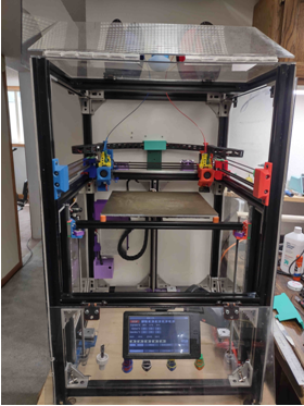
The G3d CoreIDX printer as it is setup now uses 7- mgn12H blocks with 6 - 500mm linear rails. The frames interior dimensions are 520mm wide by 510mm deep and the height is 900mm tall. Just recently I decided to go with a triple Z drive and after multiple tries I adapted the SolidCore style design concept though I modeled it from scratch. I use 3-500mm T8-2 threaded rods and 3-500mm mgn12H rails and blocks for Z drive yielding a build height of just over 400mm. The Z drive steppers were also changed so that pillow blocks hold the weight of the build plate rather than motor couplings and motors.
This printer was designed for 2 color ABS work so a good enclosure was mandatory. I used standard cabinet hinges (HD) and Lexan to allow access to the upper sides (from belts up), the front and half of the top. There are some minor air gaps but I print ABS without layer separation using a small 350 watt heater in the bottom.
I wanted brushes for the extruders to minimize drips and eliminate the need for prime towers or ooze shields when printing dual colors. Those wipers are between the print bed and the endstop positions of the X and U carriages on the gantry so that they wipe each time a tool is called or retired. This limited my print bed to about 350mm. I settled on a 330x330x6 mm Mic6 plate with a 650 watt heater powered off the mains with a 125deg C thermal fuse in circuit to prevent thermal runaway.
The motherboard is a Duet 2 wifi with 3 separate stepper drivers circuits added individually. I drive 9 steppers but get away with 8 drivers by using the Duet’s Drive 2 dual motor connectors, (the original Z drive) to drive both Y steppers. There is 1 stepper motor each for X and U, 2 for Y, 3 for Z plus 2 extruders. The 3 external drivers are TMC2209s for the new Z drive. The Sailfin extruder design came from Threewheels design (thing: 5118899.Nov 8 2021) but was highly modified for my needs. The E3d V6 volcano extruders are driven by NEMA 14 steppers. The U carriage contains an E3d V6 heatsink that has a threaded rather than the standard mount so that shims can be used to allow precision vertical alignment with the X carriage. -
CoreXY to IDEX conversion updateposted in My Duet controlled machine
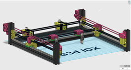
It has been over a year since I posted my IDEX project and decided I needed to provide some updates. (https://forum.duet3d.com/topic/27864/coreidx-conversion-of-a-corexy-printer-into-an-idex/7?_=1685127576825) . The machine has gone through multiple minor modifications but the CoreIDX design has remained the same. Here are several additional drawings to aid in explaining the differences between CoreXY, CoreIDX and HaqXY or Dual Markforge belt arrangements. Thank you to Haggan90 and dc42 as referenced by sonderzug, for setting up the kinematics for this back in 2019.
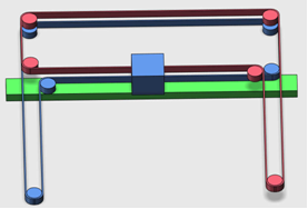 CoreXY
 CoreIDX
First I wanted to show how close the physical layout is between a CoreXY and a CoreIDX. Basically just splitting the X carriage into X and U carriages and adding a Y drive. Of course one must add an additional endstop for U and modify the system software files for the kinematic changes plus it must be setup as an IDEX system.
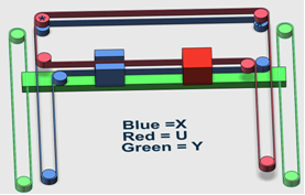 CoreIDX belt system
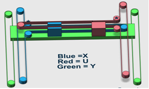
Dual Markforge belt systemNext is a quick discussion about the differences between "Dual Markforge" (which is HaqXY) and CoreIDX. They both use the same or very similar kinematics formulas as far as Duet RepRap firmware is concerned but the belt configuration is different and significant. The CoreXY belt pattern is superior to the Markforge configuration because the CoreXY belt tensions hold the gantry alignment. Note the only changes between these two belt systems are the routing of the belts and the placements of two pulleys (shown with "*"s) . The CoreIDX moves the pulleys off of the gantry and onto the opposite corner of the back frame (diagrams above) positioning pulleys like a CoreXY. That alteration makes all the difference in whether or not the gantry holds its proper right angle alignment to the frame. CoreXY theory states the gantry is held perpendicular to the Y axis, reference Ilan E. Moyer 2012 http://corexy.com/theory.html because of the pulleys and belt routing. This is true whether a single carriage (CoreXY), double carriage (CoreIDX), or no carriage (straight edge as is the case with a drafting table). The tension on the gantry presented by one CoreXY belt is countered by the tension of the other belt and gantry alignment is established by their tensions, as explained by Mark Rehorst in his “Core Belt Tensioning myths” https://drmrehorst.blogspot.com/2022/07/the-corexy-belt-tuning-myth.html If the belts are tightened to the point where the gantry is square to the printer frame and tight enough for precision movement, the gantry will be constrained by the CoreXY belts and remain perfectly aligned through all movements. That is true if the CoreXY system was designed properly in the first place. The CoreIDX belts do the same, with the new Y belts providing additional constraint.
 All HW changes shown in red
Here is CoreIDX with its latest updates that include moving from one to two Y motors for the Y drive, new carriage designs with Sailfin extruders and print cooling fans, and a new triple Z drive.
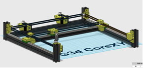
 G3d CoreIDX
Soon to be released on a Thingiverse near you,
-
RE: Problems with drivers after a HW changeposted in Duet Hardware and wiring
@Phaedrux Yes I have researched that link and my drivers were (before HW change) working fine, but that firmware issue with my second board caused my problems. Now the drivers are fixed and working as I need them to.
I have found the auto config not useful at all with my specific design and HW implementation. I needed 8 driver to run 2 carriages and my new 3 motor driver Z axis. I added 3 add on polo drivers (8825s) for the Z. I moved the Z drivers to 5,6,and 7 to maintain common driver motor combos as recommended. With this implementation of drivers, the "auto config" can not compute. I can not make the old Z driver into my new U driver as that option is not allowed (as far as I can see).
Now my only issues relate to my new Z probe (NPN inductive) not working and having gone up to RRF 3.4 I need to figure out how to get 3 point leveling working (reference, pivot, roll) to sync to three motors/drivers but that is no longer a HW or wiring issue so I'll more to a different tread/forum.
Thanks for straightening out my firmware issue! Consider this solved.
-
RE: Problems with drivers after a HW changeposted in Duet Hardware and wiring
@Strider007 Thanks, I had swapped MBs and did not check to see the status of the firmware. I'm now updated it to 3.4.4 as you described (yes WDC still worked) and all is working with my existing config.g file except for some minor issues.
I have not figured out how to make the config tool work for an IDEX system. When I attempt to add multiple drives, it will not until I add a Deux 2 or 5. Even when I do that, it still will not allow me to name one off the drives U. It only gives me the choices of X Y Z E0 E1 E2. There for I can not use that tool until someone explains to me how to get past this point of setting up the drives.
Thanks again,