This is a short discussion of a novel design conversion done to a CoreXY system, turning it into an IDEX or independent extruder system. The only additional mass added to the Y gantry is the weight of the new U carriage. Almost all of the original CoreXY components remain the same or very similar. This approach infers a lower complexity and mass on the gantry than all the IDEX systems available today. A Duet style mother board is required.
I have always loved the design of a CoreXY machine for its scalability, precision, and speed. It is a truly great design but it only supports a single X carriage or single extruder. If the desire arises for dual extrusion, the conversion ideas that I have researched have been very complicated design modifications. They consist of tool changer systems, or a new motor on the Y gantry (added mass), or a complete duplicate set of belts, pulleys and motors. I have used dual extruders on a single carriage before and the results were not predictable and often too sloppy with smearing. I need independent extruders (IDEX) for the work I do. I spent most of my “Covid pandemic time” perfecting what I think is a reasonable path for conversion of most CoreXY machines into what I will call CoreIDX, or a modified CoreXY machine that becomes an IDEX system.
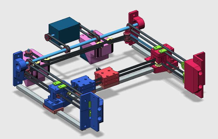
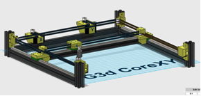
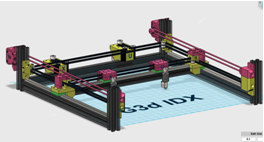
Figure 1: CAD version of a CoreIDX gantry system
My original design criterion was to create a very good CoreXY machine on a fairly large frame (~350x350x500mm print area); but this was really a fall back position if my IDEX idea didn’t work. I did not want to be wasteful so I reused as much of the original CoreXY components as possible. This concept reutilizes almost all of the original hardware by keeping the Core XY belts, pulleys and motor placements without additional motor weight to the Y gantry, only the U carriage weight is added. Figure 1 represents what I created based on a basic HEVO frame kit and design ideas found on Thingiverse.
X and U Drive
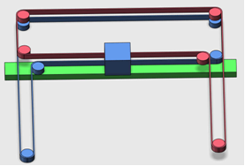
Figure 2 shows the pulleys, belts, and motors are the exact same as a CoreXY design. This conversion of a standard Core XY into a modified Cartesian IDEX is done by splitting the single X carriage into two carriages, X and U. These are now X&U belts and X&U motors .
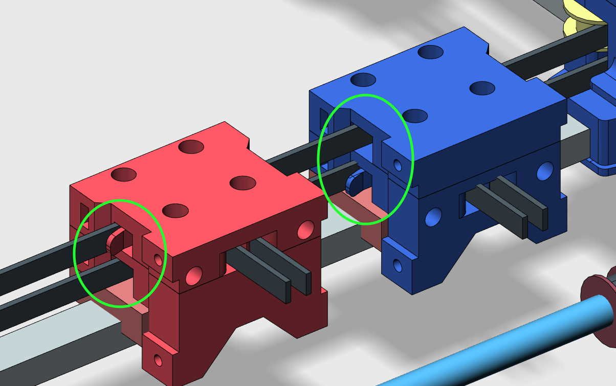
Figure 2: One belt attaches and the other passes through on the X and U carriages
Each of them now attached to only one of the two pre-existing Core XY belts allowing the other belt to freely pass through it as shown in the circled area of Figure 2.
Figure 3: Bottom view X & U carriages showing belt attachment and pass-through areas
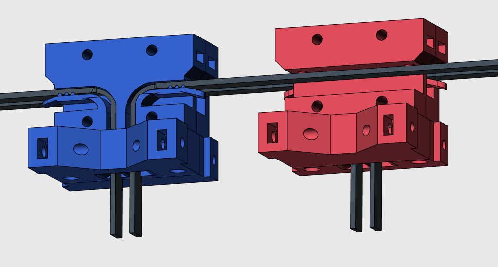
Figure 3 shows how the separation of the belts between the two new carriages was accomplished allowing a belt to attach to one carriage while passing through the other one.
This design maintains the rigidity and alignment of the Y gantry in a similar manner as the CoreXY design since belts, pulleys tensions remain the same but they no longer drive the gantry in a Y direction. Each carriage is free of the other and driven by the original X and Y motors now repurposed as X and U drive motors driving either carriage in the X directions only.
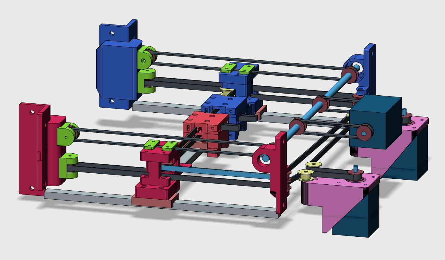
Fig 4: Y motor, shaft, and belts all mounted horizontally on top
Y Drive
The Y gantry is no longer driven or controlled by either of the two original motors. One additional motor is now required to drive the Y gantry back and forth. It is accomplished by adding the new Y motor to the back of the frame as shown in Figure 4. It drives a shaft with drive pulleys that push/pulls the Y gantry fore and aft just like many typical Cartesian printer designs. Adjustable belts pulleys are added to front of the machine to provide adjustment for the Y belt loops. This means the only added weight to the Y gantry is the weight of the additional U carriage and the attachment points for the belts and no additional motor mass since all positional drive motors are frame mounted.
Kinematics
This design maintains CoreXY belt tensions but does require modified kinematics not available to Marlin based HW/FW. The new X and U drives accurately move the two carriages in the +/- directions in a normal Cartesian manner but not the Y drive. If the Y gantry moves it will affect both X & U carriage positions. If the new Y gantry is moved, the X & U carriages either move diagonally together or apart. This means any Y movement of the gantry has to be countered by an equal movement of both the X & U motors (in opposite directions) in order to maintain their current position. This design requires hardware/firmware combination that allows for easily modified kinematics. Marlin and that class of hardware/firmware as far as I know can not accomplish this task. I do not have the programming skills to tackle C++ and/or Python therefore my logical choice was to move to a Duet style motherboard which runs RepRap firmware and capable of what I needed. With this motherboard the kinematics g-code command used is:
M669 X1:0:0:0 Y-1:1:0:1 Z0:0:1:0 U0:0:0:1.
CoreIDX Summary
The CoreIDX machine has performs flawlessly and there are no plans to revert back to CoreXY. I have successfully used it for over a year commercially with amazing results. Besides great two color printing it has been utilized in duplicate and mirror mode operation too.
 CoreXY
 CoreIDX
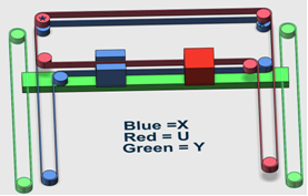 CoreIDX belt system
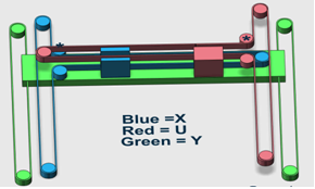
 All HW changes shown in red
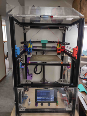 G3d CoreIDX